(210-2340) EGR pipe replacement, V6 diesel
Symptom: Coolant leakage
|
MODIFICATION INSTRUCTION
|
|
Bulletin Nbr:
|
210-2340
|
|
Date:
...........
|
April 2002
|
|
Market:
|
enligt separat lista
|
|
|
EGR pipe replacement, V6 diesel
|
Cars in stock must be remedied before delivery.
Cars already delivered must be rectified in connection with a scheduled visit to the garage for service or repairs.
Saab 9-5 M02 with engine variant D308L and VIN interval 23008028-23026471.
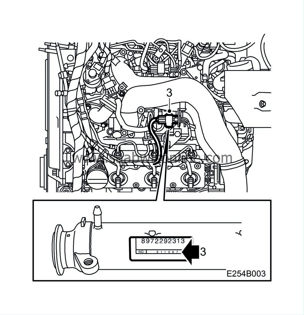
Disruptions in the manufacturing process at the supplier have lead to the possibility of crack formation in EGR pipes, which in turn results in coolant leakage. The pipes to be replaced are within the serial number intervals 301612 - 302224 and 302774 - 302938. The serial numbers are found on the cooling pipe label. Follow the check method indicated below. The EGR pipe must be replaced on a total of 778 cars.
Symptoms
Coolant leakage
53 36 144, Kit, EGR pipe
(40) 400 131 389 Coolant 1 l (enough for 4 cars)
(16) 30 06 665 Vaseline (enough for 100-200 cars)
Check box C5 on the modification identity plate before taking any action. Continue as follows if the box is not marked.
Checking serial number interval
|
1.
|
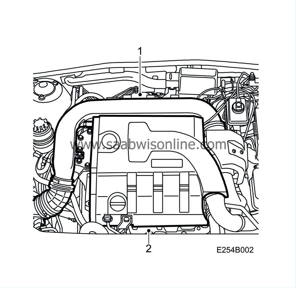
Detach the intake manifold between the mass air flow sensor and the turbocharger.
|
|
2.
|
Remove the upper engine cover.
|
|
3.
|
Unplug the glow plug connector from the front cylinder bank. Use a screwdriver to move aside the wiring obscuring the EGR valve cooling pipe and read the serial number on the label. Use a torch. Is the serial within the specified interval?
YES.
Continue with step 1 under "To remove".
NO.
Continue with the next step.
|
|
4.
|
Plug in the glow plug connector.
|
|
5.
|
Fit the upper engine cover.
|
|
6.
|
Attach the pipe between the mass air flow sensor and the turbocharger.
|
To remove
|
1.
|
Loosen the cap of the coolant expansion tank and release any overpressure. Refit the cap.
|
|
2.
|
Cover the turbocharger intake.
|
|
3.
|
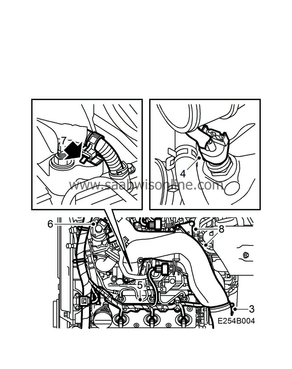
Loosen the turbo pressure hose from the upper intake manifold.
|
|
4.
|
Unplug the connector of the coolant temperature sensor
|
|
5.
|
Unplug the connectors, remove the cable bars from the camshaft covers and bend aside the engine harness for easier access.
|
|
6.
|
Unplug the EGR valve connectors.
|
|
7.
|
Loosen the cable fixing on the cable to the fuel pump by pressing down on the catch and prising out the band.
|
|
8.
|
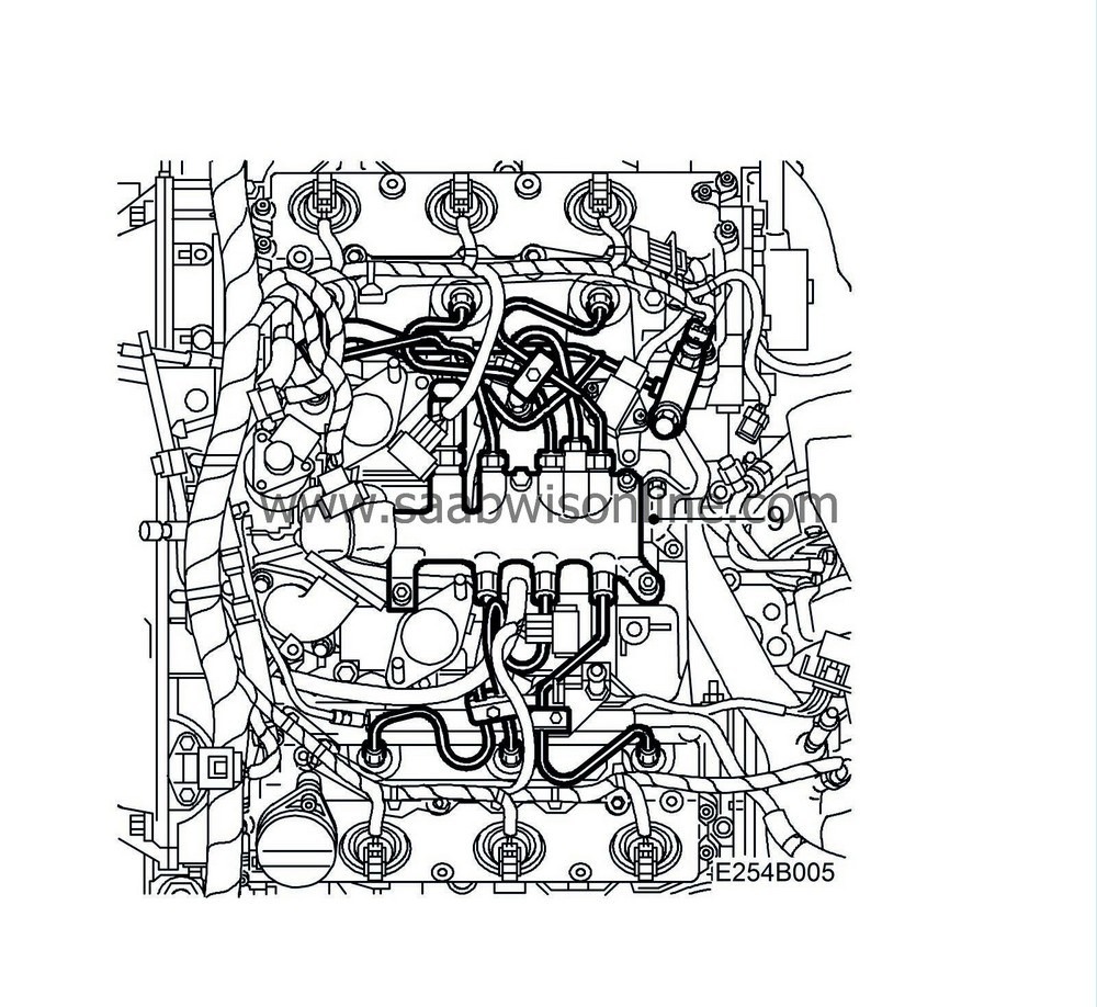
Remove the upper intake manifold and the turbocharger bracket. Cover the holes.
|
|
9.
|
Remove the fuel pipes including clips and the fuel rail.
|
|
10.
|
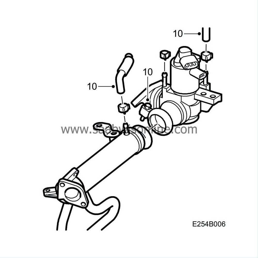
Detach the radiator hose from the EGR valve, plug the water connector and remove the screw of the V-clamp.
|
|
11.
|
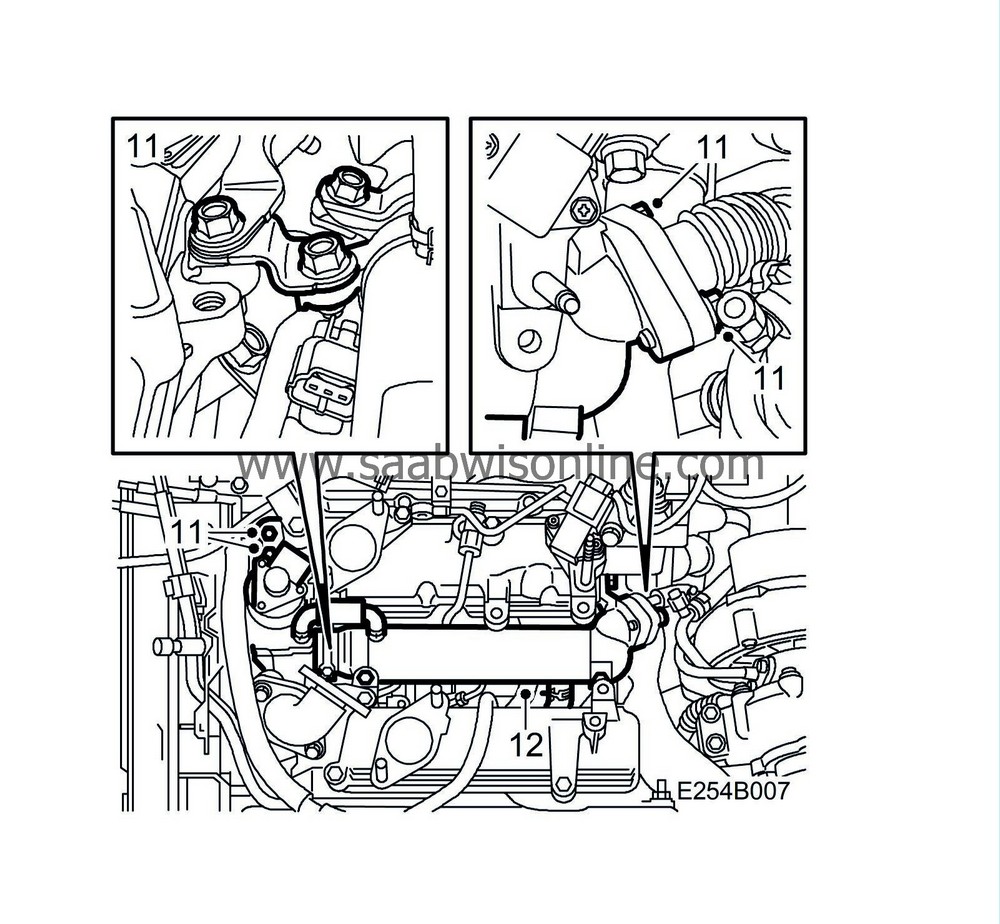
Loosen, and if necessary remove, the EGR valve screws and remove water-jacketed EGR pipe from the EGR valve and from the pipe.
|
|
12.
|
Remove the EGR valve cooling pipe with hoses from the coolant pipes on the engine. Plug the pipe ends.
|
To fit
|
Note
|
|
Not all gaskets in the repair kit are used when refitting.
|
|
1.
|
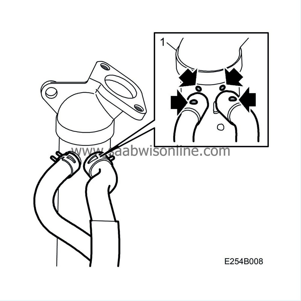
Connect the new coolant hoses following the colour marking on the new cooling pipe. The colour dots on the hoses should line up with the corresponding dots on the pipe ends to avoid hose creases.
|
|
2.
|
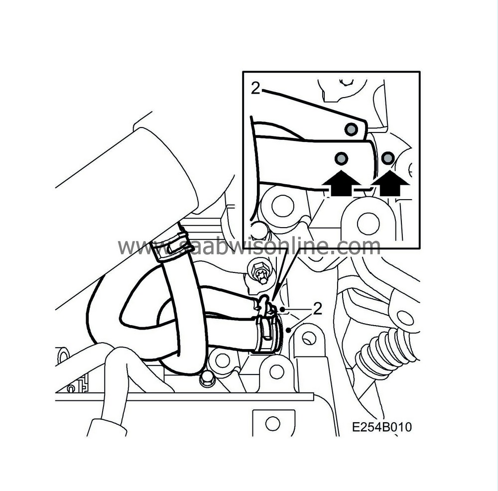
Remove the plugs and fit the under and then upper hose based on the colour markings, which should be visible from above. Use the hose clips of the kit for the hose connections.
|
|
3.
|
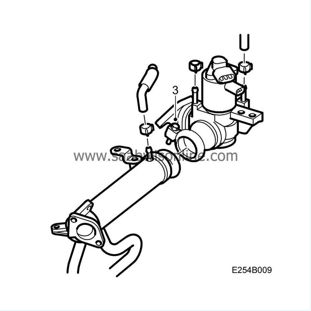
Clean the sealing surfaces and fit the EGR valve cooling pipe. All screws should be inserted only. Fit the V-clamp without tightening it. Make sure the hoses are free so that coolant flow is not restricted.
|
|
4.
|
Fit the loose brackets between the water pipe and the front bank's intake manifold. Fit a new gasket on the exhaust manifold pipe. Position the clip so that the marking is opposite the marking on the cooling pipe. Tighten the clip.
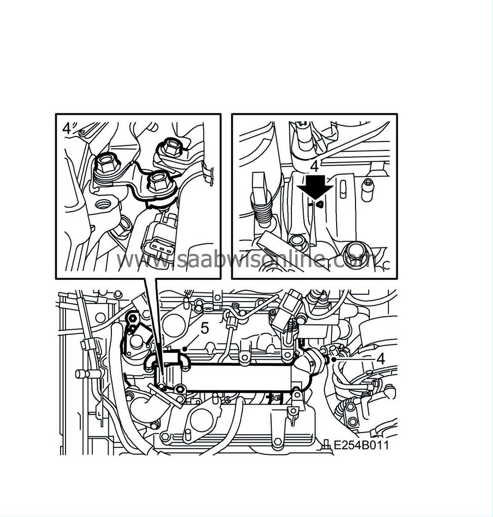
Tightening torque, screws 21 Nm (15 lbf ft)
Tightening torque, V-clamp 6 Nm (4 lbf ft)
|
|
5.
|
Remove the plug and fit a new hose between the EGR valve and the cooling pipe.
|
|
6.
|
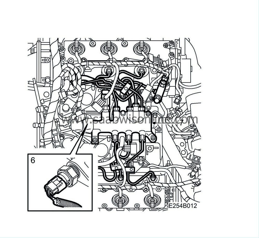
Plug in the pressure sensor connector and draw up the wiring. Fit the protective braided sleeve.
|
|
7.
|
Fit the fuel rail and new fuel pipes. Transfer the fuel pipe mountings to the new pipes. Lubricate the rubber seals sparingly with acid-free vaseline. Fit a new gasket on the banjo nipple.
Tightening torque, fuel pipes 25 Nm (18 lbf ft)
Tightening torque, fuel rail screws 21 Nm (15 lbf ft)
|
|
8.
|
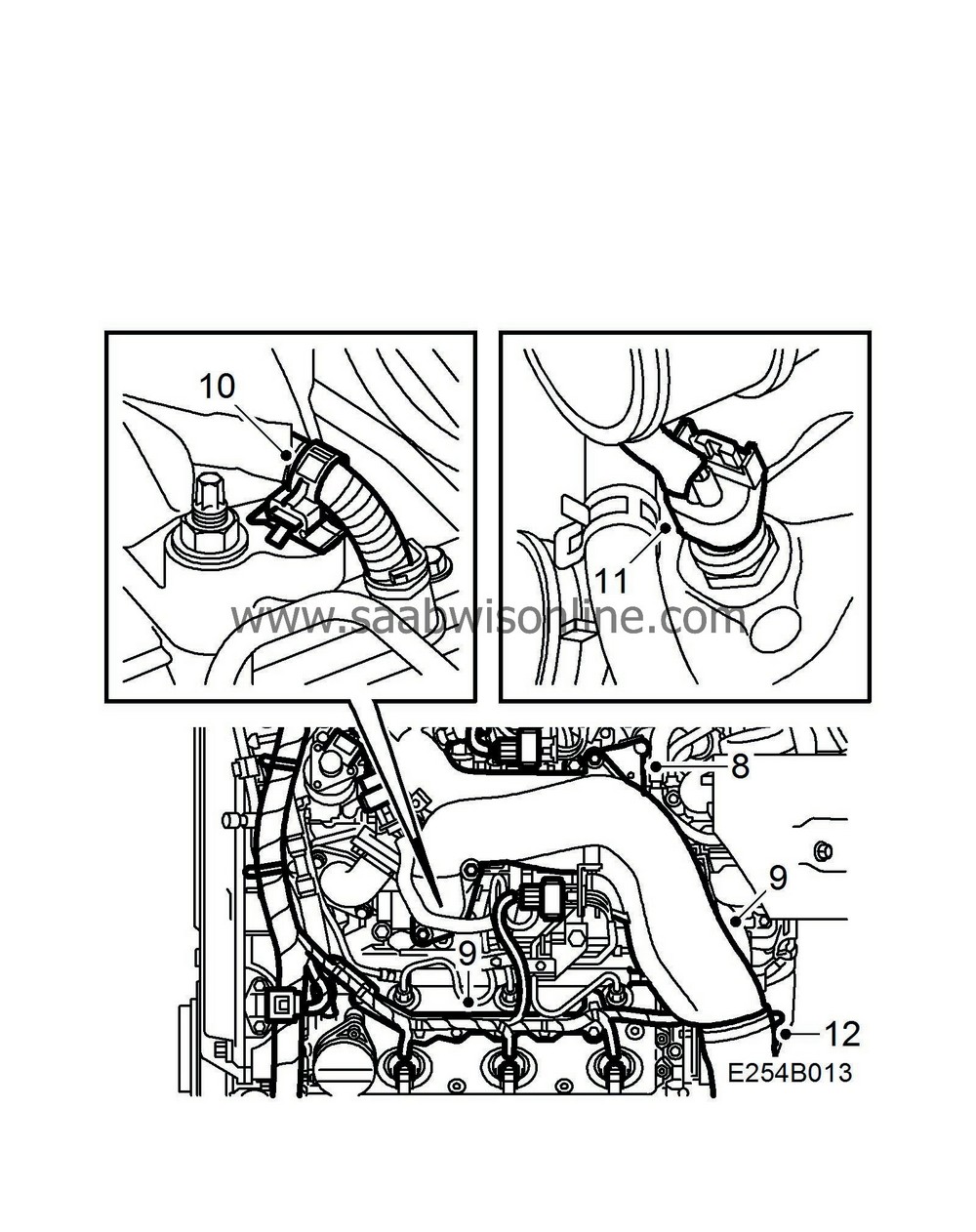
Fit the turbocharger bracket.
|
|
9.
|
Fit the upper intake manifold with new seals and fit the cable bars on the camshaft covers.
Tightening torque, upper intake manifold 21 Nm (15 lbf ft)
|
|
10.
|
Fit the cable fixing on the cable to the fuel pump.
|
|
11.
|
Plug in the coolant temperature sensor and other connectors.
|
|
12.
|
Fit the turbo pressure hose to the upper intake manifold.
|
|
13.
|
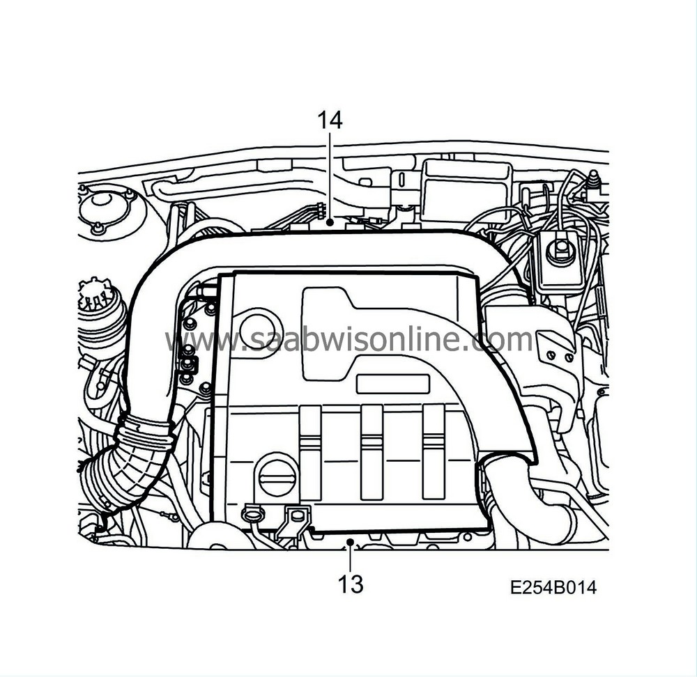
Fit the upper engine cover.
|
|
14.
|
Remove the seal from the pipe and fit the intake manifold between the mass air flow sensor and the turbocharger.
|
|
15.
|
Fill with coolant, start the engine and warm it up until the thermostat opens. Top up coolant as necessary.
|
|
Marking the modification identity plate
|
Upon completion of the procedure on affected cars in accordance with MI210-2339, MI210-2340, MI260-2342, MI432-2345 and MI871-2346, mark box C5 of the modification identity plate. If the procedure was carried out by the importer, mark the box with a "7"; if it was carried out by the dealer, mark the box with an "8".
|
Time/Warranty information
|
See separate information.


