(232-2370) Replacement of components in the V6 diesel intake system
Symptom: The functionality of the engine deteriorates due to wetness and clogged filter insert
| MODIFICATION INSTRUCTION | |
| Bulletin Nbr: | 232-2370 |
| Date: ........... | Oktober 2002 |
| Market: | all |
| Replacement of components in the V6 diesel intake system |
| Customer Satisfaction Campaign 154 13 |
Cars in stock must be rectified before delivery.
A personal communication must be sent to the owners of cars already delivered requesting them to get in touch with the nearest Saab garage as soon as possible to have the fault rectified.
| Cars affected |
Saab 9-5 M02 with engine alternative 308L and within VIN range 23000132 - 23058970.
| Background |
When driving in severe wet weather there is a risk of water entering the intake system which can result in deteriorating engine functionality.
Symptoms
The functionality of the engine deteriorates due to wetness and clogged filter insert| Parts required |
79 89 395 Clip
54 64 144 Shield for air intake
79 78 638 Screw
54 64 326 Hose filter element - mass air flow sensor
54 64 318 Hose mass air flow sensor - turbo
53 42 951 Mass air flow sensor
54 61 959 Filter insert
| Procedure |
Check box C3 on the modification identity plate before taking any action. Continue as follows if the box is not marked.
| 1. |
Raise the car.
|
|
| 2. |
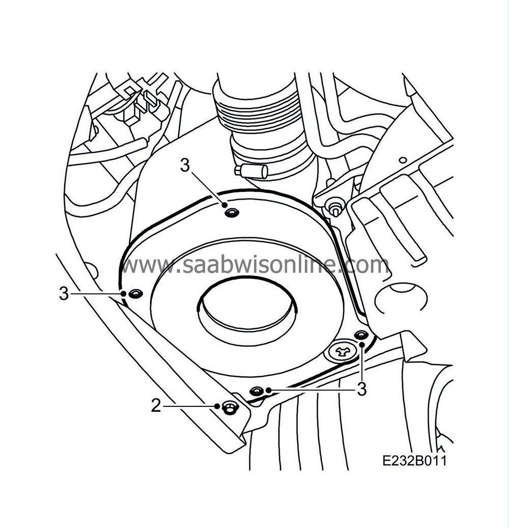
Remove the screw which holds the bumper to the wing liner.
|
|
| 3. |
Remove the air cleaner cover.
|
|
| 4. |
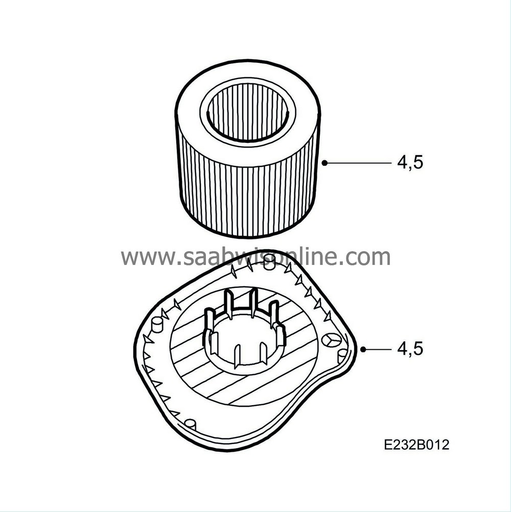
Lift the cover down and remove the filter. Clean the filter element drainage.
|
|
| 5. |
Fit a new filter and fit the air cleaner cover.
|
|
| 6. |
Lower the car and remove the centre grille by:
1A. Lift it slightly so that the lower edge loosens. 1B. Pull it forward and down so that the spring-loaded clips release. 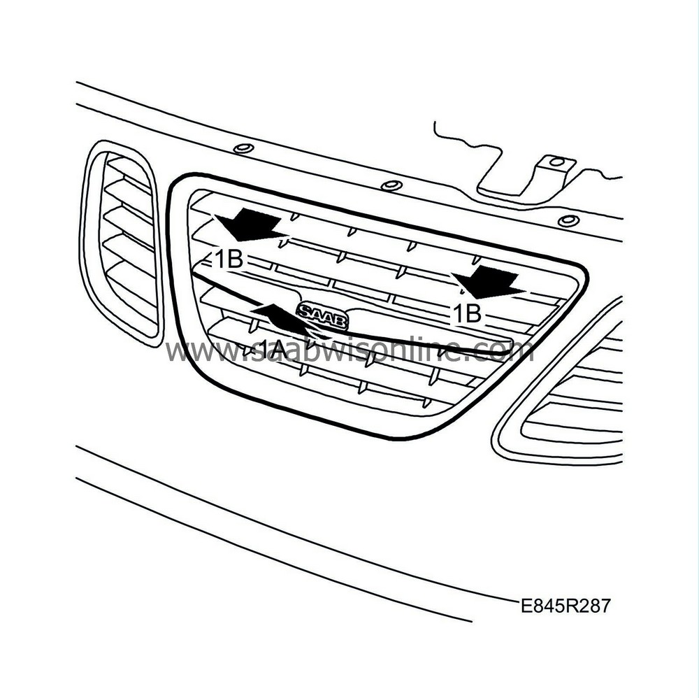
|
|
| 7. |
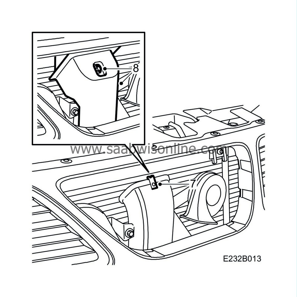
Fit the clip to the air intake.
|
|
| 8. |
Fit the shield to the air intake, make a notch in the air intake using an awl and fit the screw.
|
|
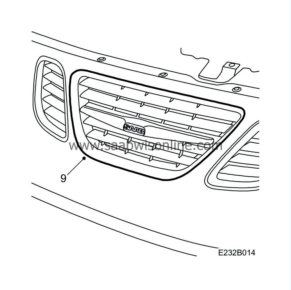
| 9. |
Fit the centre grille by pressing it in in the correct position.
|
|
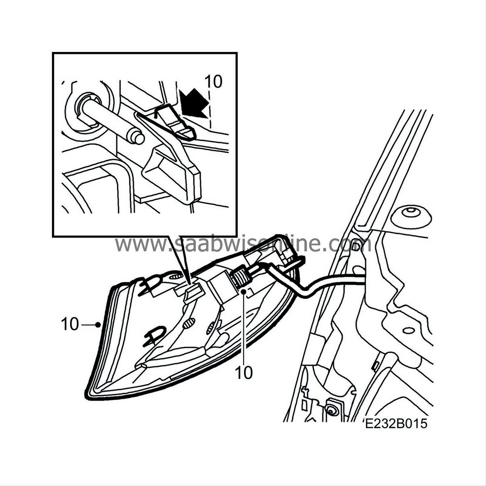
| 10. |
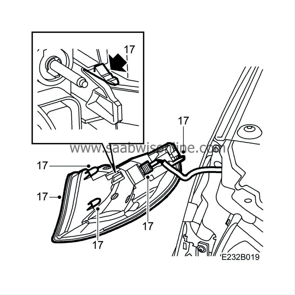
Press down on the snap fastener and remove the right-hand indicator cluster.
|
|
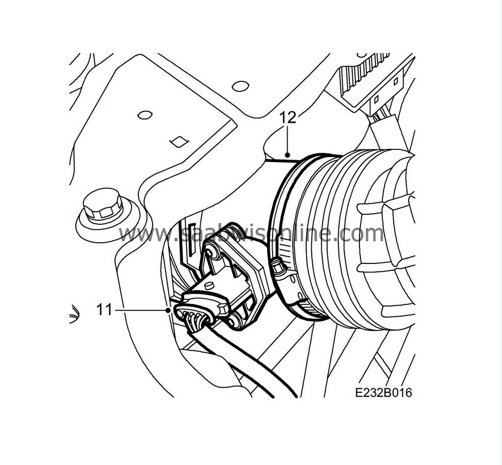
| 11. |
Remove the mass air flow sensor connector.
|
|
| 12. |
Remove the mass air flow sensor and hoses.
|
|
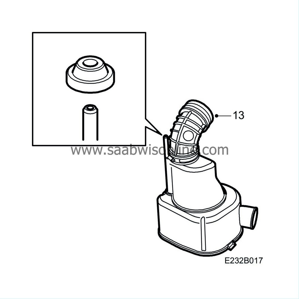
| 13. |
Fit a new hose to the air cleaner casing.
|
|
| 14. |
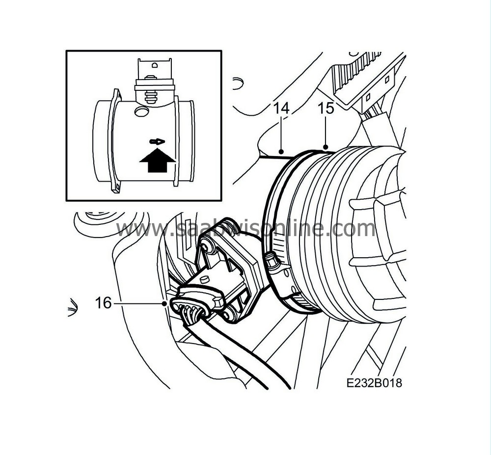
Fit the mass air flow sensor to the hose. Check that the arrow on the mass air flow sensor points in the direction of the turbo. Make sure that the hose clip does not chafe against the body.
|
|
| 15. |
Fit the hose between the mass air flow sensor and the turbo intake manifold.
Tightening torque, mass air flow sensor 3.5 Nm (2.5 lbf ft) Position the screw on the hose clip on the same side as the mass air flow sensor connector. |
|
| 16. |
Connect the mass air flow sensor connector.
|
|
| 17. |
Position the right-hand indicator so that the three guide pins are set in the correct position. Press the indicator firmly. Check that the locking clip has attached correctly.
|
|
| 18. |
Connect the diagnostic tool, read off and clear diagnostic trouble codes. Remove the diagnostic tool.
|
|
| Marking the modification identity plate |
After carrying out the procedure on cars affected as per MI210-2365, MI232-2370, MI248-2369 and MI410-2372 box C3 on the modification identity plate must be marked. Mark the box with the number "7" if the procedure was carried out by the importer or with the number "8" if carried out by the dealer.
| Standard times-/Warranty information |
See separate information.


