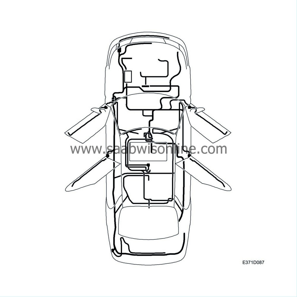
System overview
| System overview |
| Wiring harnesses |
Saab 9-5 has eight wiring harnesses: front, power train, dashboard, front door, rear door, roof, tailgate and rear.
They connect all the electrical components in the car to their intended points of connection.
Some components have their own harnesses for distributing power in the component. The electrically adjustable seat is one such example.
| Main fuse boxes |
All electrical distribution units are part of a wiring harness. The distribution units contain all the car's fuses and relays, with the exception of the relay in the passenger seat which allows operation without the ignition being on.
The engine bay contains:
| • |
maxi-fuse box 501

|
|
| • |
main fuse box in engine bay 342a

|
|
| • |
main relay board in engine bay 342b

|
|
The main fuse box 342a and main relay board 342b in the engine bay are built in to one unit.
The distribution units in the dashboard are divided into two separate units:
| • |
main fuse box 22a

|
|
| • |
main relay board 22b

|
|
| Power supply |
Power supply for the car is divided into:
| • |
Battery supply
|
|
| • |
+30-supply
|
|
| • |
Power supply (+15 circuit)
|
|
| • |
Power supply (+54 circuit)
|
|
| • |
+X-supply
|
|
| • |
+B-supply
|
|
Battery supply
In addition to being supplied to the maxi fuse box 501, the battery voltage is also supplied directly to the starter motor, generator, both lighting relays as well as a number of fuses in the engine compartment main fuse box and fuse A in the dashboard main fuse box, see .
.
These leads are unfused and great care must be exercised when measuring the voltage in these circuits.
The charging system is described in service category “Charging Systems”
 .
.
+30-supply
When the ignition is in the LOCK position and the key is removed, certain fuses and components are still supplied with power. The power supply comes first via one of the maxi fuses and a certain protection exists against short-circuiting. Great care is also recommended when measuring voltage before the fuses in the dashboard main fuse box and ignition switch, stalk switch, ignition switch relay, main relay for engine management system and start relay, see .
.
+15-voltage
When the ignition key is turned to the ON or START position, power is supplied from connector pin 15 to a number of fuses in the dashboard main fuse box, see .
.
The voltage remains even when the key is turned to the START position.
+54-voltage
In the ON position, voltage is supplied from connector pin 54 to some fuses in the main fuse box in the dashboard as well as the relay coil at ignition relay 21. The relay closes and voltage is supplied via its connector to fuses both in the engine compartment and dashboard fuse boxes, see .
.
When the ignition key is turned to the START position, the current is cut. This is to disconnect a large number of consumers during the start procedure so that the starter motor and engine management system will receive the highest possible voltage and ensure engine start.
+X-voltage
When the ignition key is turned to OFF from LOCK, voltage is fed from the X-pin to the light switch, see .
.
The power supply is interrupted when the key is turned to the LOCK position.
+B-voltage
When the ignition key has been turned to OFF from LOCK, voltage is fed from pin B to fuse 5 in the dashboard main fuse board, see .
.
The power supply is only interrupted when the key is removed from the ignition.


