(410-2372) Replacement of cruise control switch on the clutch pedal
|
MODIFICATION INSTRUCTION
|
|
Bulletin Nbr:
|
410-2372
|
|
Date:
...........
|
Oktober 2002
|
|
Market:
|
all
|
|
|
Replacement of cruise control switch on the clutch pedal
|
|
Customer Satisfaction Campaign 154 13
|
Cars in stock must be rectified before delivery.
A personal communication must be sent to the owners of cars already delivered requesting them to get in touch with the nearest Saab garage as soon as possible to have the fault rectified.
Saab 9-5 M02 with 3.0 TiD engine and within VIN range 23000132 - 23058970.
The engine management system uses the signal from the cruise control switch on the clutch pedal. Due to the short travel on the switch the signal is given very early when depressing the pedal. In some positions it is sufficient for the driver's foot to rest on the clutch pedal.
Engine and transmission then react as with a gear shift. This is felt as a jerk in the engine. The problem is most evident with town driving.
LHD
55 32 205 Cruise control switch
55 32 213 Fitting adapter, cruise control switch
55 43 632 Adapter wiring harness
79 71 864 Cable tie
RHD
55 32 205 Cruise control switch
55 32 213 Fitting adapter, cruise control switch
55 43 632 Adapter wiring harness
79 71 864 Cable tie
91 20 775 Sleeve (x2)
Check box C3 on the modification identity plate before proceeding. Continue as follows if the box is not marked.
LHD
|
1.
|
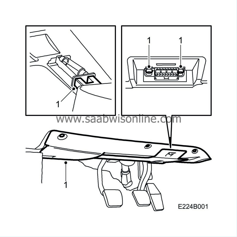
Remove the pedal bracket cover by undoing the 3 screws and the clip. Turn the cover downwards and pull out carefully.
Remove the data link connector and the connector from the floor lighting.
|
|
2.
|
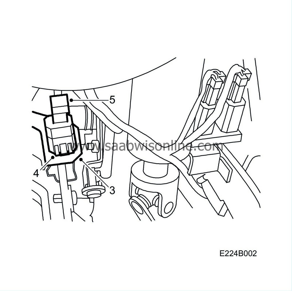
Press down on the clutch pedal.
|
|
3.
|
Pull out the switch pushrod and the red sleeve.
|
|
4.
|
Press in the locking tab on the switch using a small screwdriver and remove the switch.
|
|
6.
|
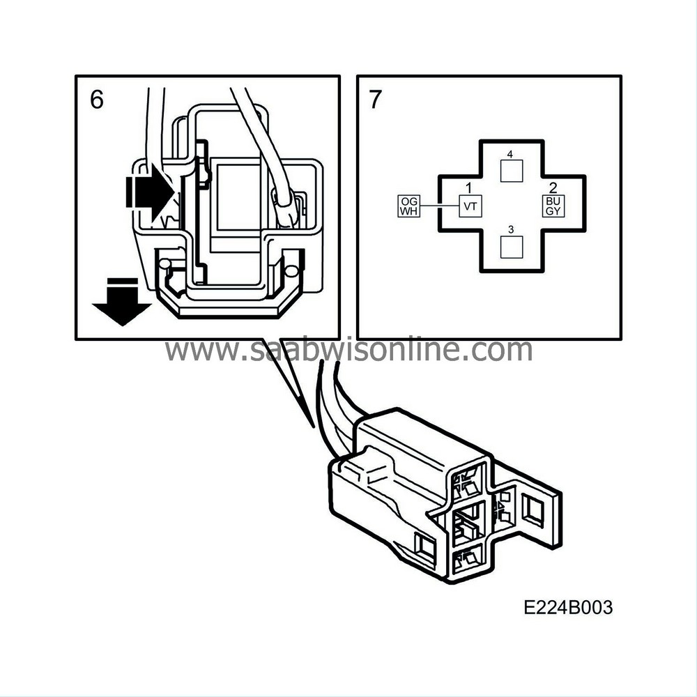
Remove the rear protection and pin from the sleeves using 85 80 151 Kit, connector pin removal tool.
|
|
7.
|
Pin the sleeves in the new connector.
Red/blue cable to position 1 and orange/white cable to position 2.
|
Note
|
|
Carefully pull in the cables in order to ensure that the rear protection on the sleeves has locked.
|
|
|
8.
|
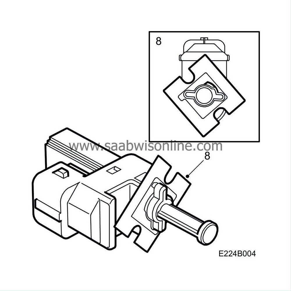
Fit the fitting adapter to the new switch.
|
|
9.
|
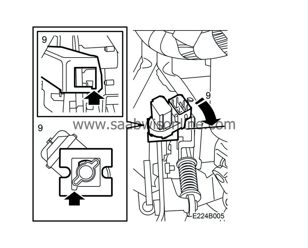
Press down on the clutch pedal.
Fit the new switch to the clutch pedal bracket by positioning the fitting adapter in the hole in the bracket and turn the switch 45° clockwise.
|
Note
|
|
When the switch is turned it must be pressed accurately against the bracket.
|
|
|
10.
|
Release the clutch pedal.
|
|
11.
|
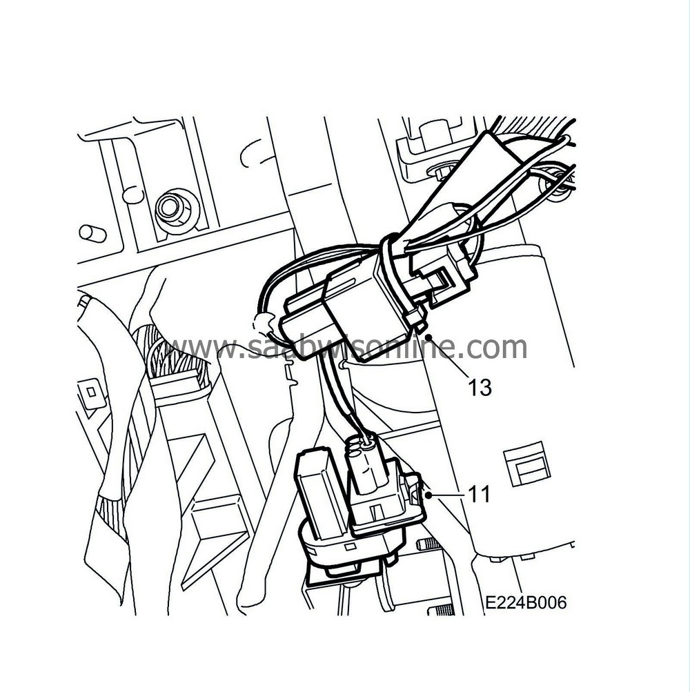
Connect the adapter harness to the switch.
|
|
12.
|
Connect the adapter harness to the new connector.
|
|
13.
|
Fit the adapter harness and the new connector to the existing wiring harness using a cable tie and cut off.
|
|
14.
|
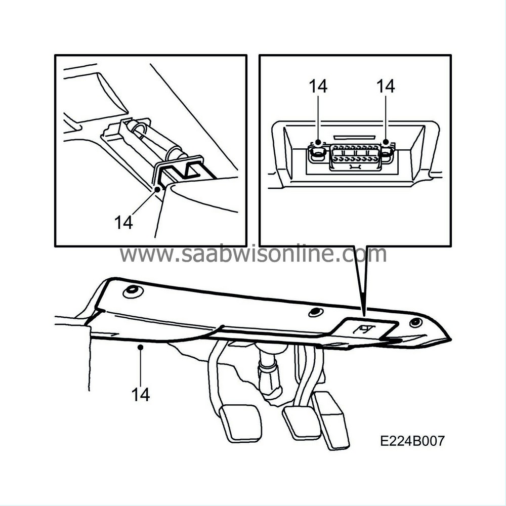
Fit the data link connector and connect the connector to the floor lighting.
Fit the pedal bracket cover using 3 screws and 1 clip.
|
RHD
|
1.
|
Remove the pedal bracket cover by undoing the 3 screws and the clip. Turn the cover downwards and pull out carefully.
Remove the data link connector and the connector from the floor lighting.

|
|
2.
|
Press down on the clutch pedal.
|
|
3.
|
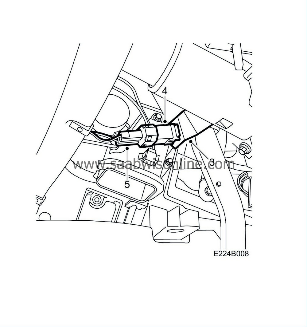
Pull out the switch pushrod and the red sleeve.
|
|
4.
|
Press in the locking tab on the switch using a small screwdriver and remove the switch.
|
|
6.
|
Cut off the connector and fit new sleeves, part no. 91 20 775. Use 86 12 079 Toolbox, wiring harness.
|
|
7.
|
Pin the sleeves in the new connector.
Red/blue cable to position 1 and orange/white cable to position 2.
|
Note
|
|
Carefully pull in the cables in order to ensure that the rear protection on the sleeves has locked.
|
|
|
8.
|
Fit the fitting adapter to the new switch.

|
|
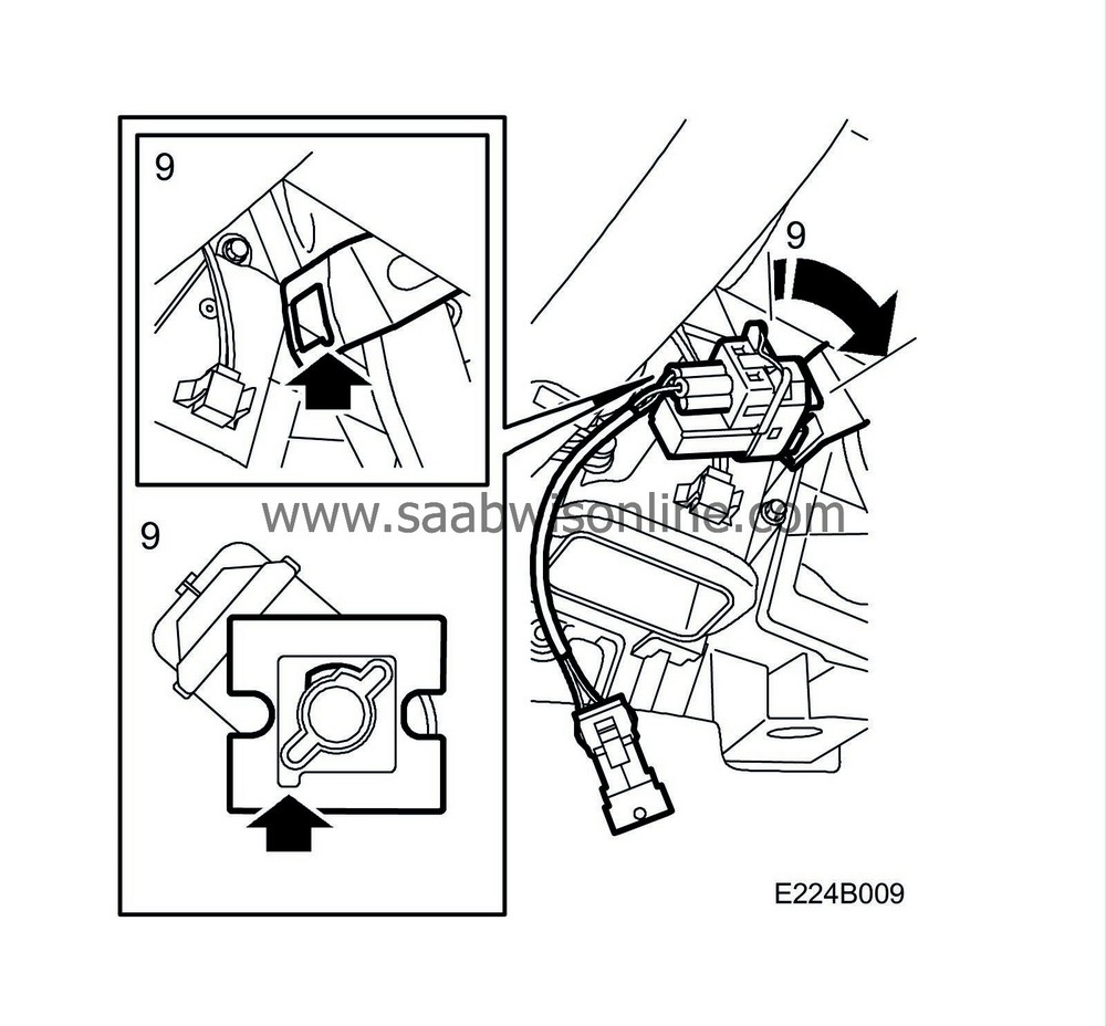
9.
|
Press down on the clutch pedal.
Fit the new switch to the clutch pedal bracket by positioning the fitting adapter in the hole in the bracket and turn the switch 45° clockwise.
|
Note
|
|
When the switch is turned it must be pressed accurately against the bracket.
|
|
|
10.
|
Release the clutch pedal.
|
|
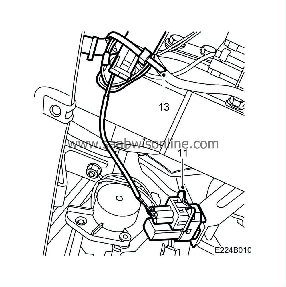
11.
|
Connect the adapter harness to the switch.
|
|
12.
|
Connect the adapter harness to the new connector.
|
|
13.
|
Fit the adapter harness and the new connector to the existing wiring harness using a cable tie and cut off.
|
|
14.
|
Fit the data link connector and connect the connector to the floor lighting.
Fit the pedal bracket cover using 3 screws and 1 clip.

|
|
Marking the modification identity plate
|
After carrying out the procedure on cars affected as per MI210-2365, MI232-2370, MI248-2369 and MI410-2372 box C3 on the modification identity plate must be marked. Mark the box with the number "7" if the procedure was carried out by the importer or with the number "8" if carried out by the dealer.
|
Time/Warranty information
|
See separate information.


