To assemble
| To assemble |
| General measures before assembly |
| • |
Parts and housing should be thoroughly washed before assembly.
|
|
| • |
Check the parts for wear. Change damaged or defective parts.
|
|
| • |
If there was a lot of swarf in the gearbox, all bearings should be replaced. Always change both bearings on one shaft, even if only one is damaged.
|
|
| • |
Change seals at the drive shafts.
|
|
| • |
Prior to assembly lubricate all bearings and friction surfaces with the same grade of oil as used in the gearbox. Refer to Technical data,
Summary of lubricants and sealants
.
|
|
| 1. |
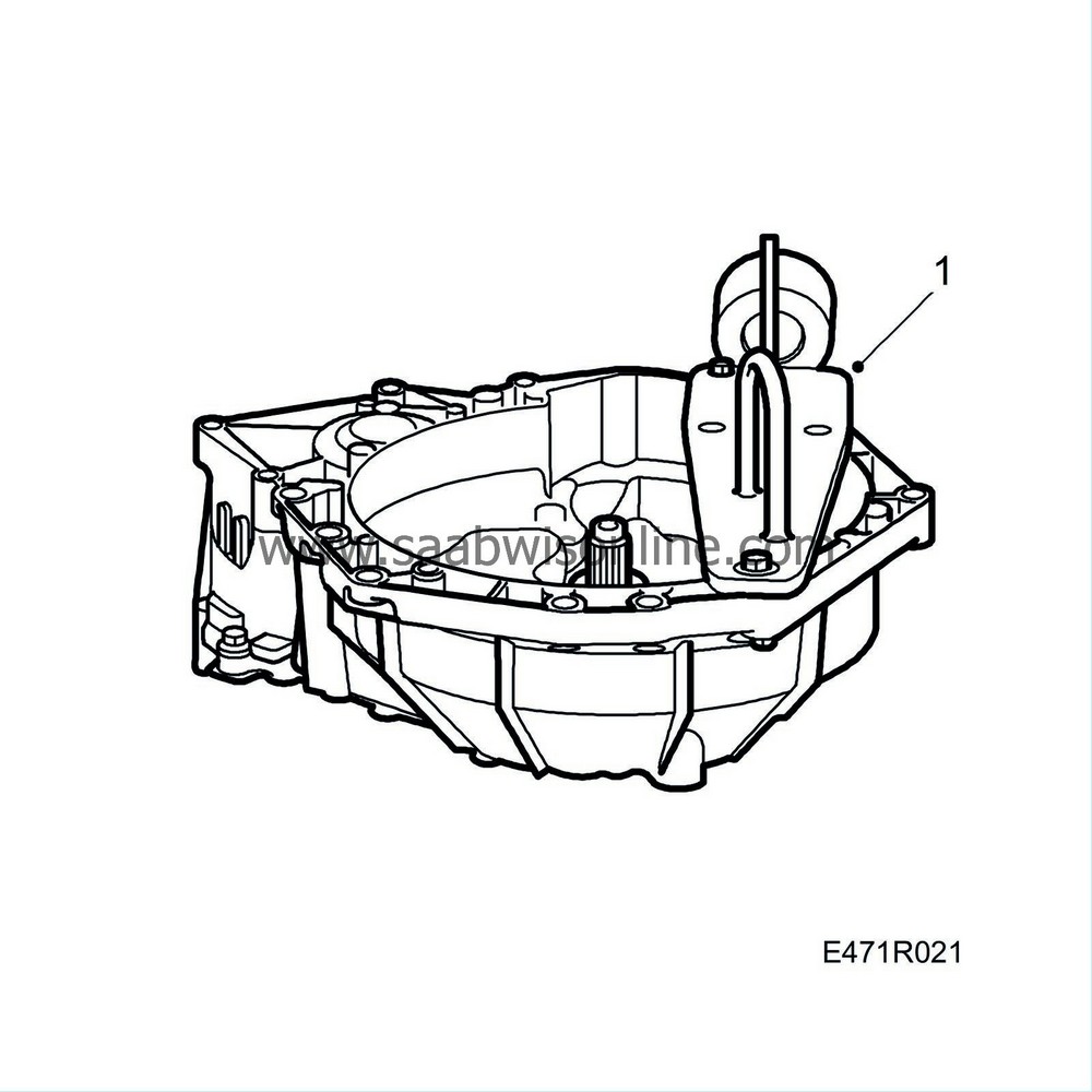
Mount the clutch housing on the work stand using
87 92 228 Holder, transmission
.
|
|
| 2. |
Carefully scrape away any remains of sealing compound from the mating face without damaging the surface. Remove all sealant remains from the gearcase.
|
|
| 3. |
Fit the differential into the clutch housing and lubricate the bearing.
|
|
| 4. |
Secure the output shaft in its seat, lubricate the bearing and fit the bearing race. Position the bearing support and tap it into place. Use
87 92 202 Sleeve
and
87 91 204 Sleeve, bearing race
. Apply locking adhesive
74 96 268 Thread locking adhesive
to all bolts and then fit them. Tighten the 3 bolts in the middle alternately.

Tightening torque 45 Nm (33 lbf ft) The outer bolts should only be tightened to: Tightening torque 24 Nm (18 lbf ft) |
|
| 5. |
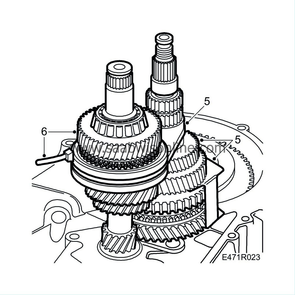
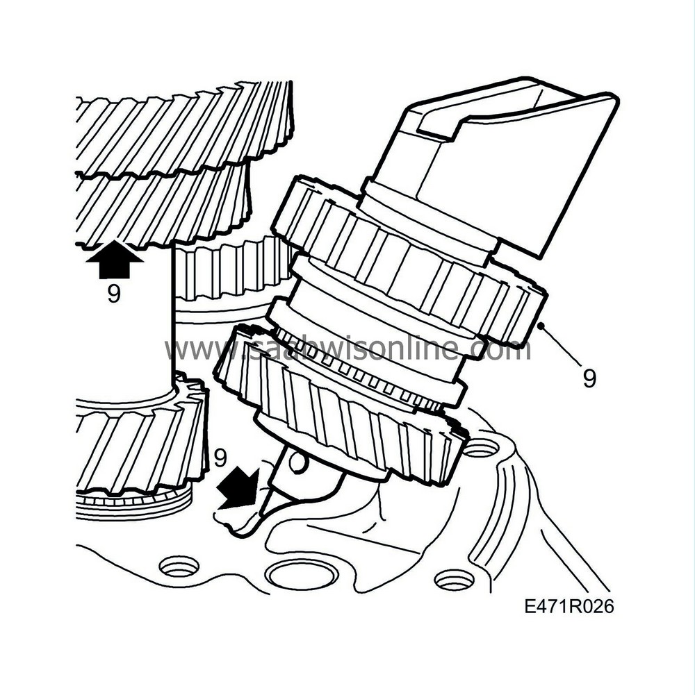
Assemble the 1st and 2nd gear wheels together with the synchromesh units using
87 92 103 Assembly fixture, 1
. Then fit the assembled parts on the output shaft. Fit 3rd gear wheel and spacer sleeve on the output shaft. Note that a used pinion must be re-fitted with its original orientation. Do not let the fitted gear wheels slide too far down the shaft, save 15 mm. Otherwise the input shaft cannot be fitted.
|
|
| 6. |
Place the input shaft in the housing and lubricate the bearing. Fit a cable tie to keep the gears on the input and output shafts meshed.
|
|
| 7. |
Press down the gears on the output shaft against the surface of the clutch housing. Tap carefully with a hammer and
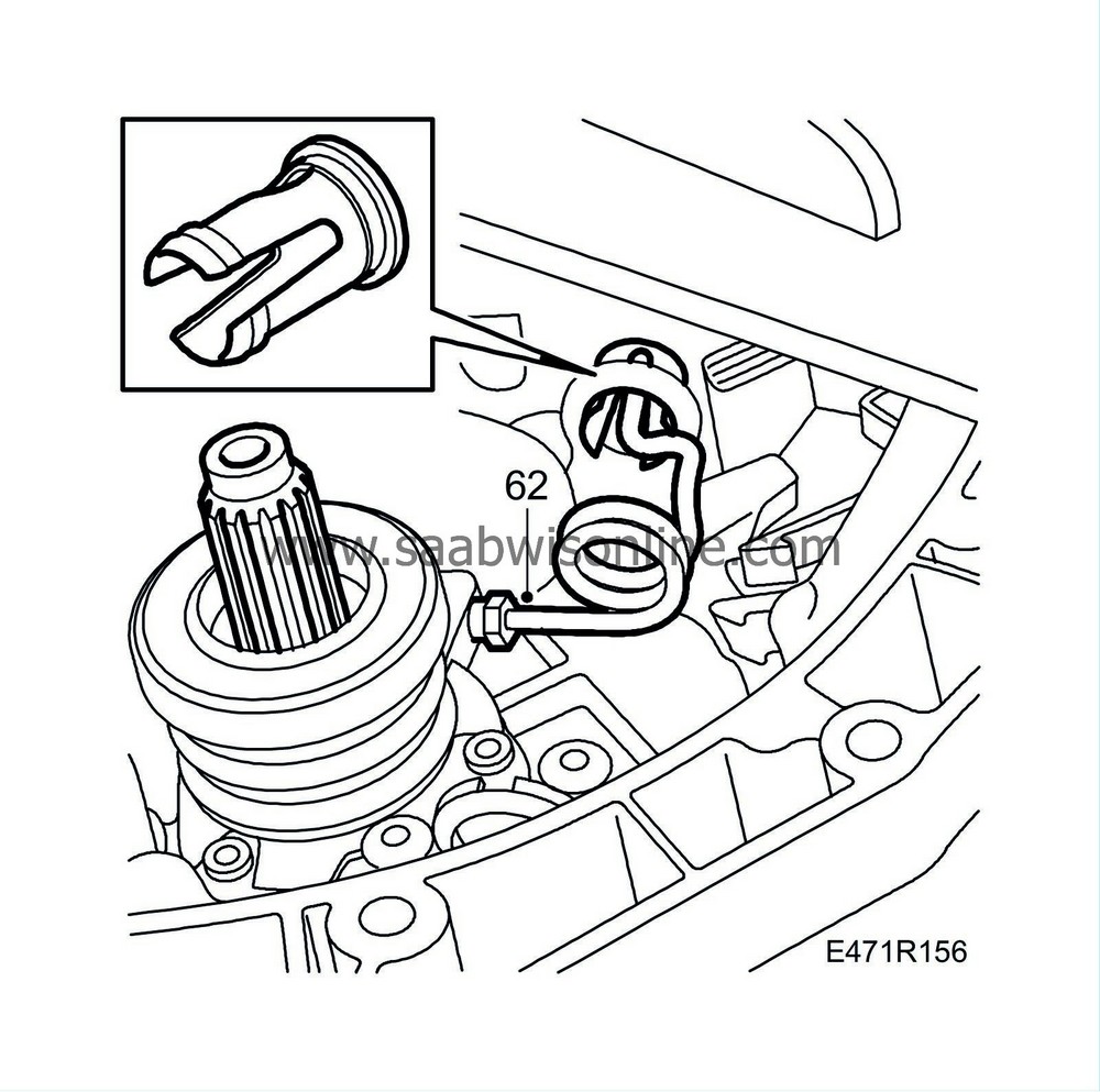
87 91 204 Sleeve, bearing race
and
87 90 867 Assembly ring, input shaft bearing
until a
new retaining sleeve
and the 4th gear can be fitted. Fit the 4th gear with the turned groove facing downwards.

|
|
| 8. |
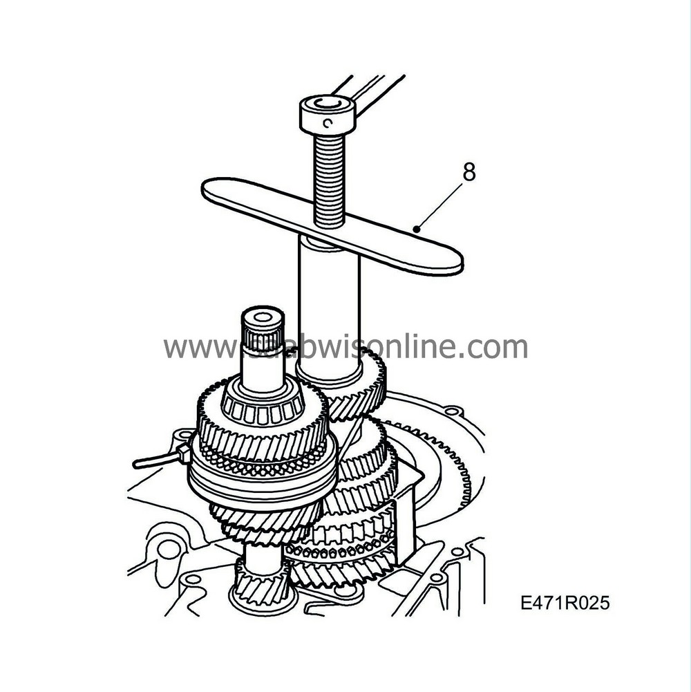
Fit
87 91 261 Puller, pinion
and pull down until the 4th gear pinion and gear on the input and output shafts are aligned. Cut the cable ties and remove the
87 92 103 Assembly fixture, 1
. Check that the 1st and 2nd gear pinions run freely on the output shaft.
|
|
| 10. |
Fit the selector mechanism in the clutch housing. The forks should be in the neutral position. Press up the synchromesh sleeve against the 2nd gear position on the output shaft. Press up the synchromesh sleeve in 4th gear position on the input shaft

|
|
| 11. |
Place the 1st-2nd and 3rd-4th forks in the synchromesh sleeves and turn and push the mechanism into position. The synchromesh sleeves should be in the neutral position. Insert the locating sleeves and align the screws.
|
|
| 12. |
Fit the reverse gear selector fork with the two remaining bolts. Use
Thread locking adhesive, Loctite 577
on the short bolt. (The bolthole opens into the clutch housing and the thread adhesive will prevent oil leakage.) Tighten the 3 bolts.
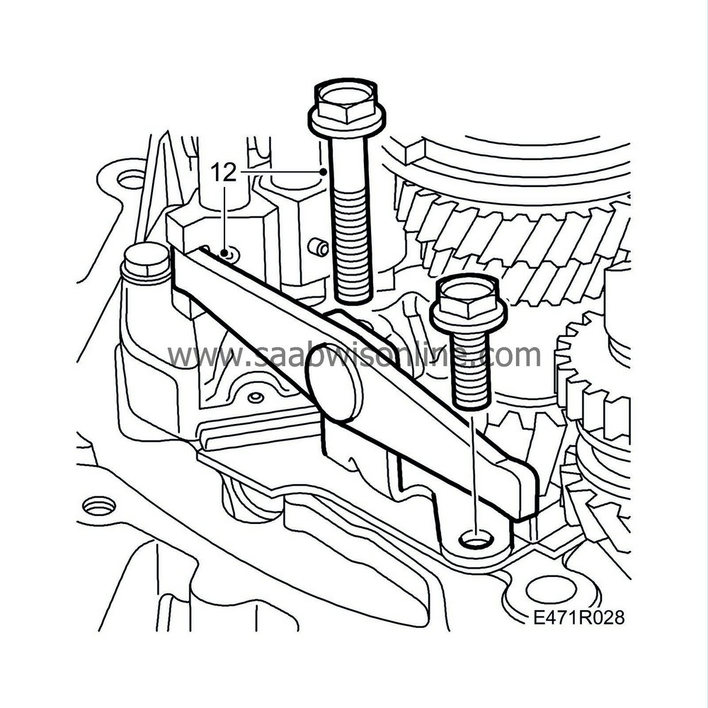
Tightening torque 24 Nm (18 lbf ft)
|
||||||||||
| 13. |
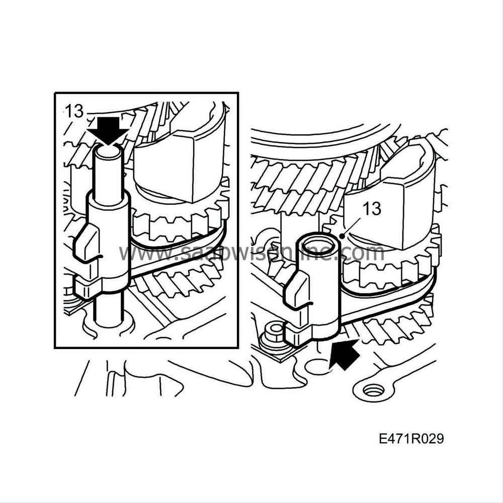
Fit the fork to the reverse synchromesh sleeve. Check that the reverse gear selector fork enters the groove on the reverse fork. Then push in the shaft. Engage reverse gear using the selector mechanism and check that it is fully engaged.
|
|
| 14. |
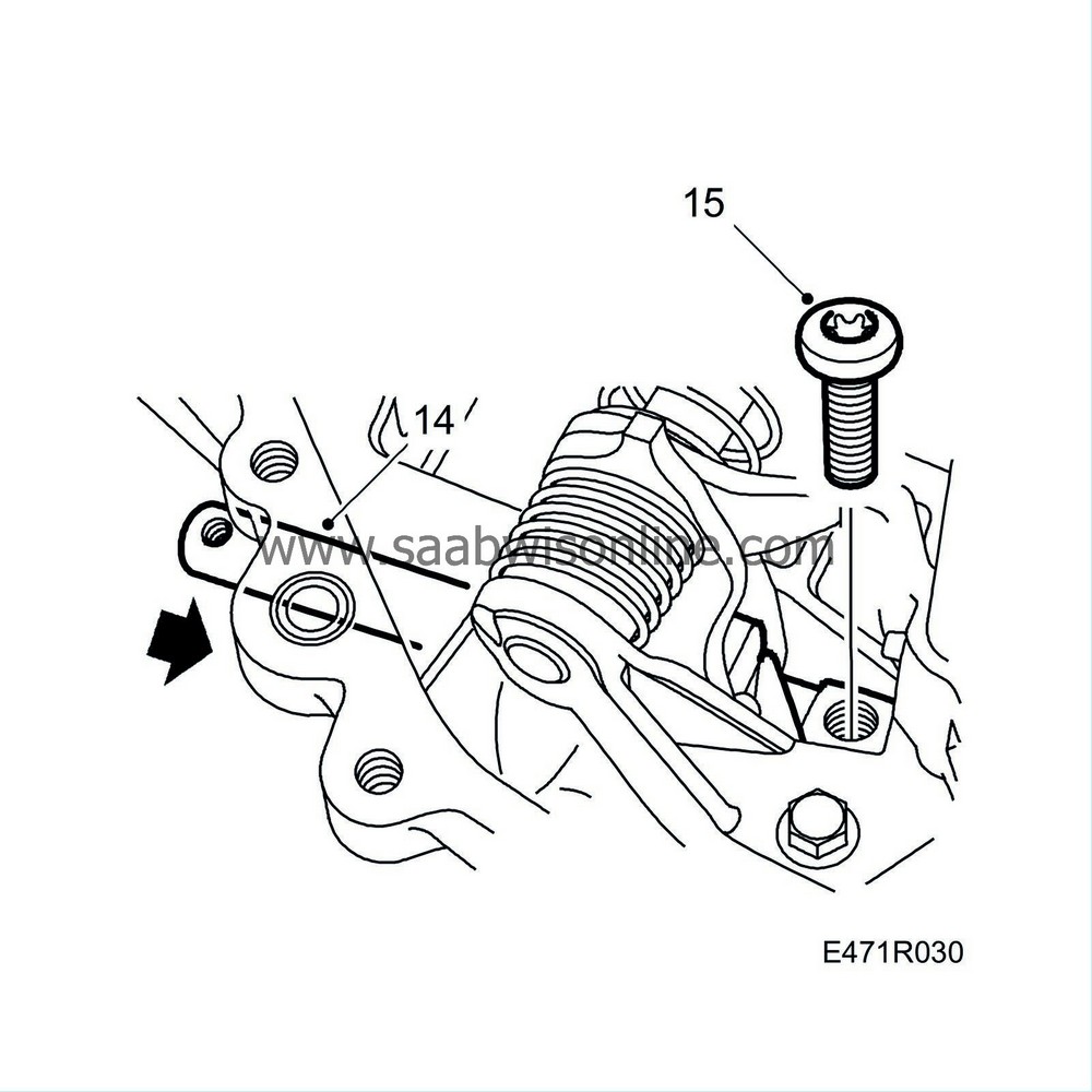
Fit the gear selector rod into position, sparingly lubricated with gearbox oil according to
Summary of lubricants and sealants
. Fit a new seal.
|
|
| 15. |
Thread in and mount the driver in position. Push in the gear selector rod and fit the screw.
Tightening torque 24 Nm (18 lbf ft) |
|
| 16. |
Check that all gears can be engaged. Also check the dual interlock feature by engaging 1st and then attempting to engage reverse by pushing in the reverse gear fork using a screwdriver. If reverse can be engaged, the locking pin in the selector mechanism must be checked.

|
|
| 17. |
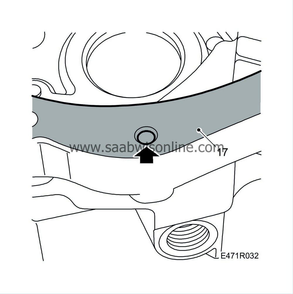
Clean the sealing surfaces thoroughly with
Cleaning agent, Loctite Super Clean 7063
. Apply
93 21 795 Flange sealant
sparingly to the contact surfaces on the gearcase and the clutch housing. Apply the Loctite and allow to dry for a couple of minutes.
|
||||||||||
| 18. |
Check that the reverse shaft support is correctly positioned so that a new screw can be fitted after the gearcase fitted. Position the gearcase on the clutch housing.

|
||||||||||
| 19. |
First lightly attach the clutch housing and gearcase using two bolts. Following which, tap up the locating sleeves. Loosely fit the bolt for the reverse shaft. If necessary, use a narrow screwdriver to guide the bolt hole up to the hole in the gearcase. Fit the remaining bolts. The three lower marked bolts should be replaced with quality 10.9.
Tightening torque 24 Nm (18 lbf ft) Tightening torque for lower marked bolts of quality 10.9, 31 Nm (23 lbf ft) 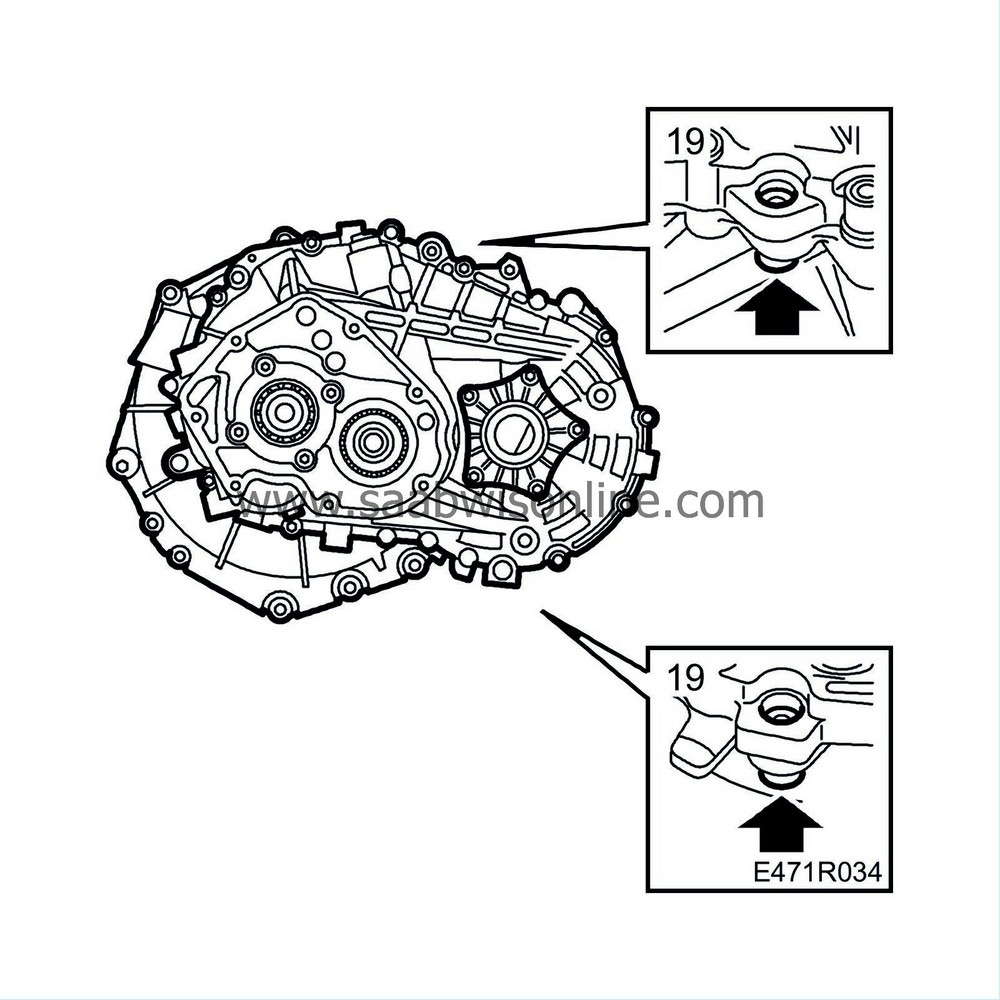
|
|
| 20. |
Tighten the screw for the reverse shaft. Note the O-ring!
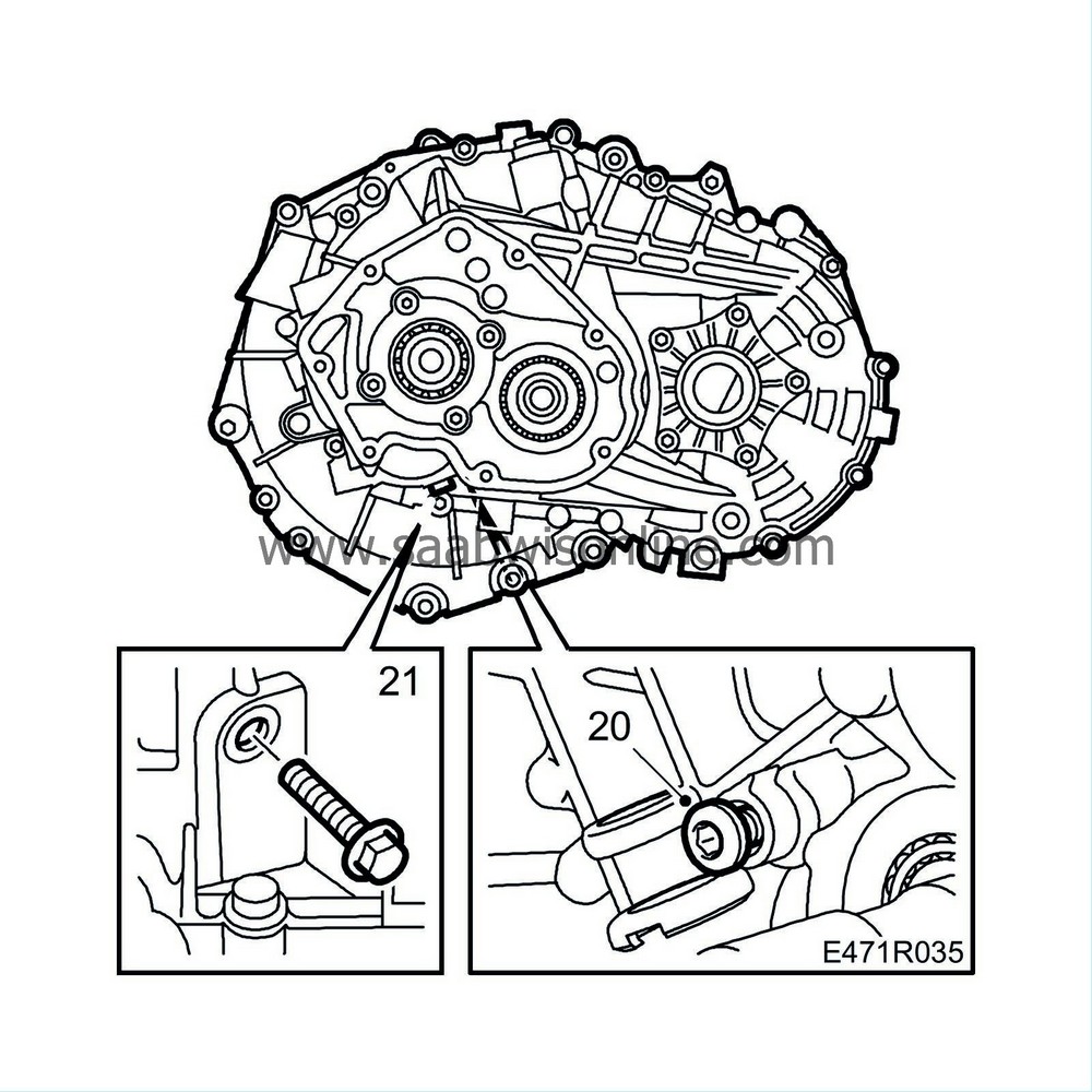
Tightening torque 24 Nm (18 lbf ft) |
|
| 21. |
Tighten a new flange bolt (quality 10.9) to the reverse shaft support. If a 10.9 bolt was already used, this can be refitted. (The quality designation is stamped on the head.) The flange bolt specified above must not be fitted to gearboxes lacking a sufficiently large flange seat. The large flange has Ø = 21 mm, and the small Ø = 17 mm.
Tightening torque (quality 8.8), 20 Nm + 120° (15 lbf ft + 120°) Tightening torque (quality 10.9), 31 Nm (23 lbf ft) Tightening torque (bolts without flange), 28 Nm (21 lbf ft) |
|
| 22. |
Fit the bearing on the output shaft, lubricate the bearing and pull it with
87 91 261 Puller, pinion
. Only pull until it is up against the retaining sleeve.
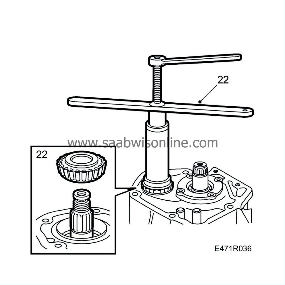
|
|
| 23. |
Fit the gear wheel for 5th gear on the output shaft. Tap down the gear wheel for 5th gear a short distance using a hammer and
78 41 067 Sleeve, bearing, inner driver
. Fit
87 91 261 Puller, pinion
. Pull down the gear wheel towards the bearing using the tool and then fit a new nut.
|
||||||||||
| 24. |
Fit
87 91 428 Driver
on the input shaft. Position the measuring tip of the indicator gauge against the input shaft bearing. Fit a drill on the tool and "run" the gearbox so that the bearings "settle in". First push whilst rotating 20 revolutions and then reset the gauge. Then lift whilst rotating another 20 revolutions (or until the value has stabilized) and then read off the value. Measure the axial clearance, which should be 0.09-0.15 mm. (The clearance will decrease to 0.04-0.11 mm when the output shaft bearings are adjusted to the correct preload). Adjust with shims under the bearing support as necessary. Shims are available in dimensions 0.1, 0.15 and 0.30 mm
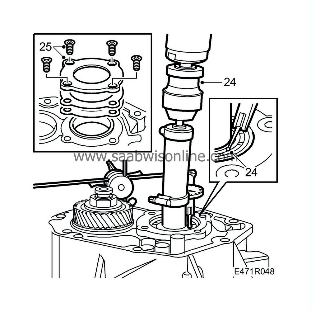
|
|
| • |
Thicker shims=increase clearance
|
| • |
Thinner shims=decrease clearance
|
| • |
Shims are available in dimensions 0.10; 0.15; 0.30 mm.
|
||||||||||
| 25. |
When adjusting axial play on input shaft:
Undo and remove the 4 screws from the bearing support. Refit the bearing support together with the correct package of shims and tighten alternately. Tightening torque 38 Nm (28 lbf ft)Check play again. Remove the three tools. |
|
| 26. |
Fit
87 92 517 Holding tool, input shaft
to the input shaft as a support when the 5th gear synchromesh hub is tapped down.
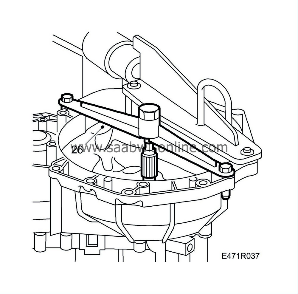
|
|
| 27. |
Fit the 5th pinion with needle bearing. Lubricate the bearing.
|
|
| 28. |
Assemble the wire ring, the 3 leaf springs, synchromesh baulk ring and hub using
87 92 582 Fixture, 5
2. Tap the hub down with
78 41 067 Sleeve, inner driver bearing
on the input shaft splines.

The synchromesh stops must align directly with the deep teeth gaps on the synchromesh hub . |
|
| 29. |
Remove
87 92 582 Fixture, 5
.
|
|
| 30. |
Fit the 5th synchromesh sleeve with the tip angles down.
|
|
| 31. |
Fit
87 92 194 Dial gauge kit
towards the gear wheel using
87 90 727 Bracket, dial gauge
.
|
|
| 32. |
Engage 1st gear and press down the 5th gear synchromesh sleeve so that the gearbox is "locked". Tighten the nut and measure alternately with the dial indicator until the axial play of the output shaft is 0.06 ±0.05 mm. Use a short M8 screw in the sealing plane as break point. Disengage 1st and 5th gears.

|
||||||||||
| 33. |
Check and adjust the preload of the differential as follows:
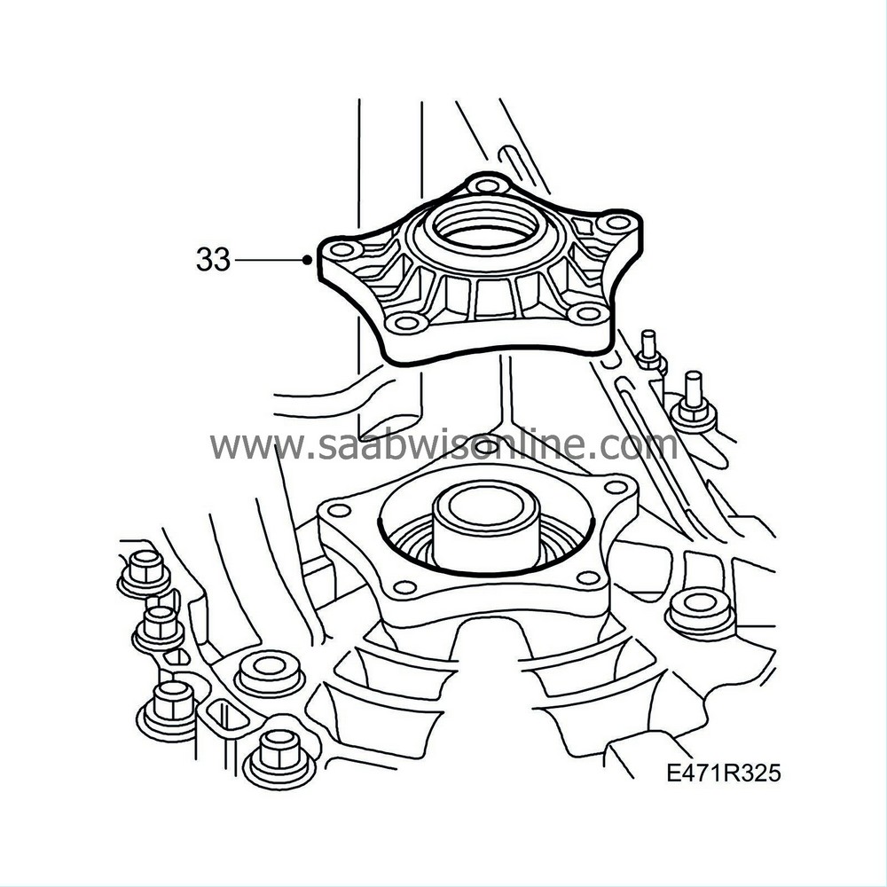
Thread in the bearing race, but not all the way. Fit the bearing support without O-ring, shaft seal and shims. Tighten 4 screws. Tightening torque 24 Nm (18 lbf ft) |
|
| 34. |
Fit
87 90 727 Bracket, dial gauge
using
87 92 194 Dial gauge kit
in the available hole. Set the tip at the differential housing. Run the output shaft using a drill and
87 92 053 Driver
until the value on the dial gauge has stabilised. Reset the dial gauge.

|
|||||||||
| 35. |
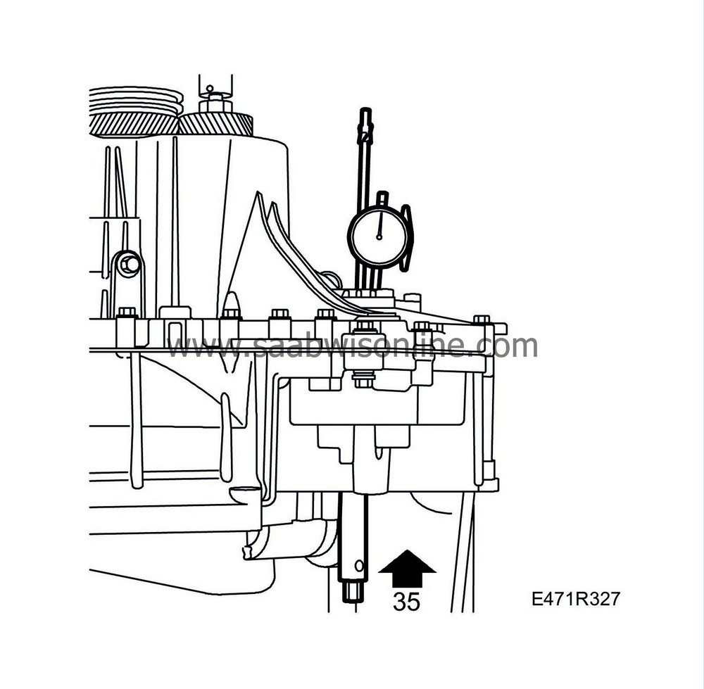
Lift the differential using
87 91 337 Driver, measuring differential bearing torque
and read the value on the dial gauge. The correct shim thickness is: measured value plus the value from the table.
|
|||||||||
| • |
Thicker shims=increase preload
|
| • |
Thinner shims=reduce preload
|
| • |
Shims for the differential are available in sizes 0.10, 0.15, 0.30, 0.50 mm
|
| 36. |
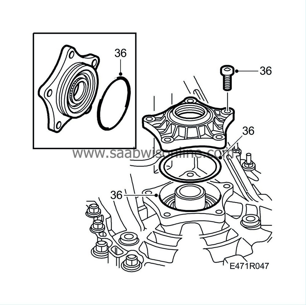
Remove the dial gauge, stand and bearing support. Fit and grease the O-ring on the bearing support. Fit the bearing support with the measured shims. Pull down the bearing support until it reaches "measured nominal value +0.15 mm".
|
||||||||||
| 37. |
Turn the gearbox so that it is in the same position as it would be in the car, i.e. horizontal.
|
|
| 38. |
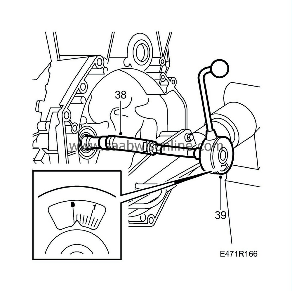
Fit the M8 fuel hose (approx. 100 mm long) between
87 91 428 Driver
and the hexagonal socket (M8 with 1/2" drive). Check that no gear is engaged.
|
||||||||||
| 39. |
Connect the torque wrench (graduated in Nm) and rotate the wrench clockwise several revolutions at even speed. Read off the average value while rotating, normally 0.10-0.30 Nm.
If the value is greater than 0.30 Nm or if it varies greatly while rotating, either the baulk rings or dirt and cuttings in the bearing are slowing it down. Dismantle the gearbox and investigate the cause. Rotating the shaft backwards and forwards under axial load may help. The bearings must be oiled in later, however. |
|
| 40. |
Turn the gearbox back around.
|
|
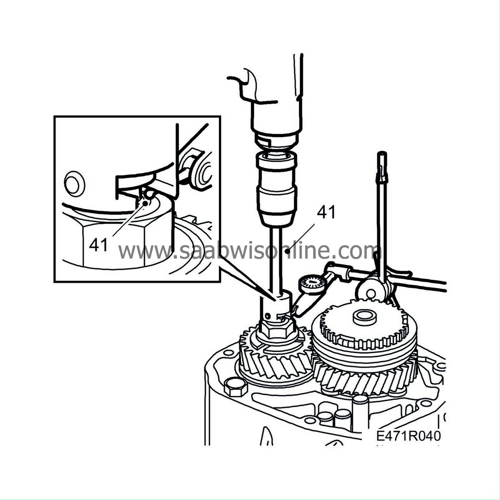
| 41. |
Position the measuring tip of the dial indicator on the shaft as illustrated. Fit the
87 92 053 Driver
onto the output shaft and "run" the gearbox with a drill so that the bearings "settle in". Press and run 20 revolutions first before resetting the gauge. Lift and run another 20 revolutions and then read off the value (or run until the value has stabilized). Remove the tool.
Note the reading for the end play and then add on the nominal value
. Remove the dial indicator.
|
|||||||||
| 42. |
Engage 5th gear by pushing down the synchromesh sleeve. Engage 1st gear.
|
|
| 43. |
Remove the
87 92 053 Driver
from the output shaft.

|
|
| 44. |
Fit
87 92 061 Millimetre wheel, 27 mm
onto the output shaft nut. Set the scale (mm wheel) on the tool to the calculated value (recorded + nominal, see example). Each division corresponds to 0.01 mm. Mark out a tooth on the gear wheel using a marker pen or the like.
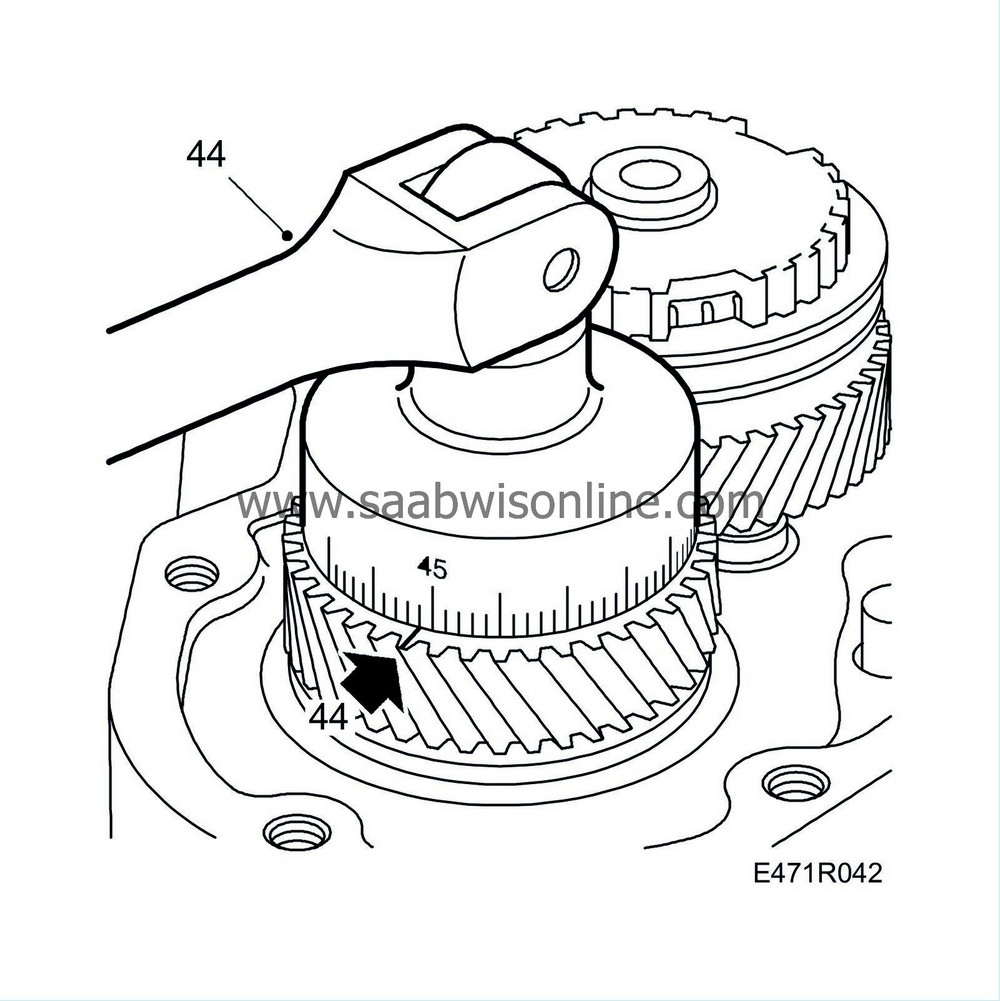
Example: Recorded value 0.43 + 0.03 (nominal value, above 5 000 km) = 0.46 mm Check the rolling torque on new bearings only |
|||||||
| 45. |
Tighten in 2-3 stages until the zero (0) mark on the tool (mm wheel) is aligned with the marked tooth. Measure the end float as described in steps 41-45. Remove the tool and the sleeve.
If old bearings are fitted to the output shaft, lock the nut and continue with step 52. If new bearings are fitted, do not lock the nut and continue with the next step. 
|
|
| 46. |
Before taking a more precise measurement of the output shaft bearing preload, the following must be complied with:
Input shaft bearing (axial play 0.09 - 0.15 mm) Differential, bearing support fitted but not tightened (axial play 0.10 - 0.20 mm) All bearings oiled |
|
| 47. |
Turn the gearbox so that it is in the same position as it would be in the car, i.e. horizontal. Disengage 1st gear and lift off the 5th synchromesh sleeve.
|
|
| 48. |
Place the torque wrench at the 5th gear nut output shaft. No gear must be engaged. Rotate the torque wrench several turns clockwise at an even speed. Read the average value from the display during rotation.

|
|
| 49. |
The average value should be 0.5 - 1.0 Nm.
Tighten the nut on the output shaft (5th and 1st engaged) two millimetre divisions at a time on the 87 92 061 Millimetre wheel, 27 mm 1, until the correct rolling torque (0.5 - 1.0 Nm) is attained. Average torque varies greatly : Cause: Retarding baulk rings, swarf or dirt in the bearings. Action: Dismantle the gearbox. Average torque higher than 1.0 Nm: Cause: Same as above or bearings too tight Action: Dismantle the gearbox and change clamping sleeve. The bearings should then be preloaded and checked. |
|
| 50. |
Lock the nut
|
|
| 51. |
Turn the gearbox back around.
|
|
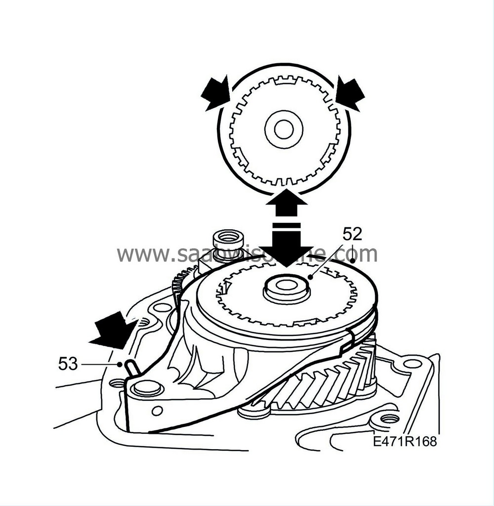
| 52. |
Lift off the 5th synchromesh sleeve and fit the 5th fork to the 5th synchromesh sleeve. Fit the fork and sleeve to the shaft.
|
||||||||||
| 53. |
Tap the retention pin into the selector shaft.
|
|
| 54. |
Fit a new circlip.
|
|
| 55. |
Tighten the screws for the differential bearing support.
Tightening torque 24 Nm (18 lbf ft) |
|
| 56. |
Remove the cover from the hole in the gearcase and fit a new gasket and the end plate.
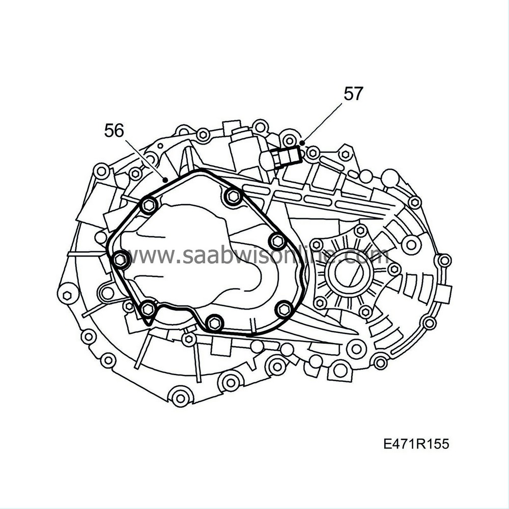
Tightening torque 24 Nm (18 lbf ft) |
|
| 57. |
Refit the reversing-light switch with a new washer if it has been removed.
Tightening torque 24 Nm (18 lbf ft) |
|
| 58. |
Check that the magnet is in position in the oil drain plug. Fit the plug.

Tightening torque 50 Nm (37 lbf ft) |
|
| 59. |
Lubricate the seal rings for input shaft and drive shafts.
|
|
| 60. |
Fluid is not added until the drive shafts are fitted on the gearbox and the gearbox is fitted in the vehicle. Quantity: 1.9 litre; see Technical data
List of lubricants and sealants
.
|
|
| 61. |
Fit the slave cylinder using
Thread locking adhesive, Loctite 577
on the screws.
Tightening torque 10 Nm (7 lbf ft) |
|
| 62. |
Fit delivery pipe in place and fit the bush.
|
|
| 63. |
Bleed the slave cylinder before the gearbox is mounted. See
Bleeding of slave cylinder
.
|
|

 Warning

