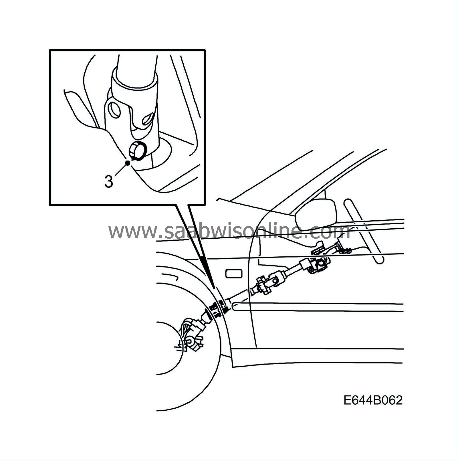
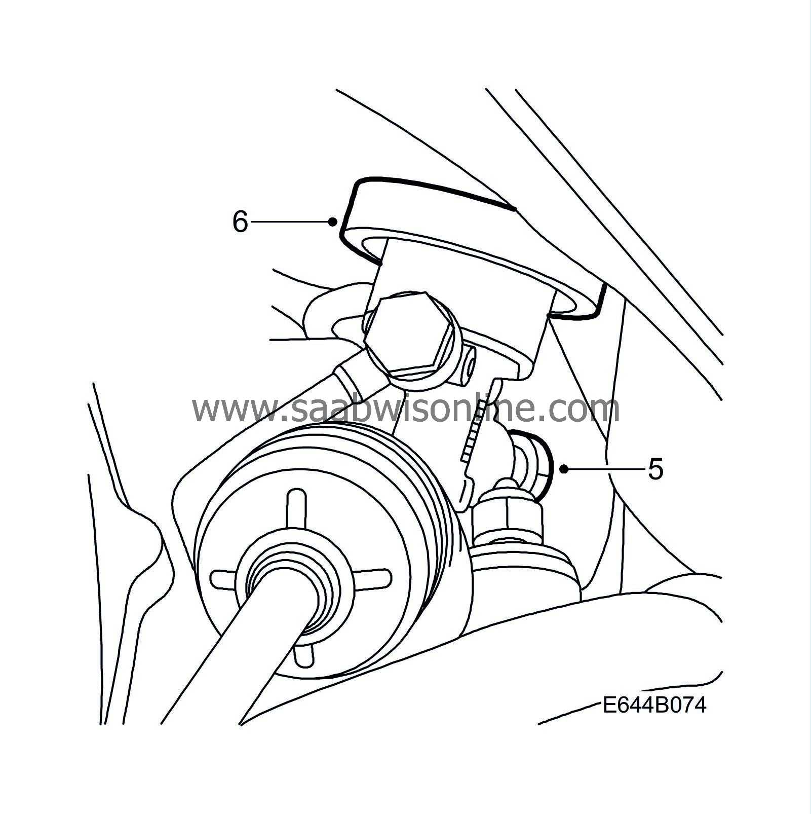
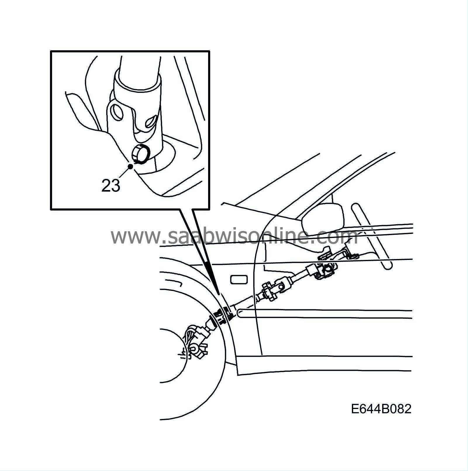
(644-2319) Securing delivery line for power steering
Symptom: No power steering effect. Leakage of power steering oil. Excessive noise from power steering pump.
| MODIFICATION INSTRUCTION | |
| Bulletin Nbr: | 644-2319 |
| Date: ........... | November 2001 |
| Market: | Enligt lista |
| Securing delivery line for power steering |
| Customer Satisfaction Campaign 154 06 |
Cars in stock must be rectified before delivery.
A personal communication must be sent to the owners of cars already delivered requesting them to get in touch with the nearest Saab garage as soon as possible to have the fault rectified.
| Cars affected |
Saab 9-5 M02 LHD with V6 diesel engine and Vehicle Identification Number 23000132-23013315.
| Background |
The power steering system delivery line may have been incorrectly installed causing it come in contact with the alternator. This can result in damage to the delivery line and leakage of power steering oil which may cause power steering failure.
Symptom description
No power steering effect.Leakage of power steering oil.
Excessive noise from power steering pump.
| Parts required |
For securing undamaged line.
48 07 939 Cable tie with mounting79 71 880 Cable tie
For change of damaged line
89 96 860 Servo oil (enough for two cars)52 36 088 Delivery line, power steering
79 71 880 Cable tie, 2
| Procedure |
Before proceeding, check box B4 on the modification identity plate. If the box is not filled in, continue as follows.
| 1. |
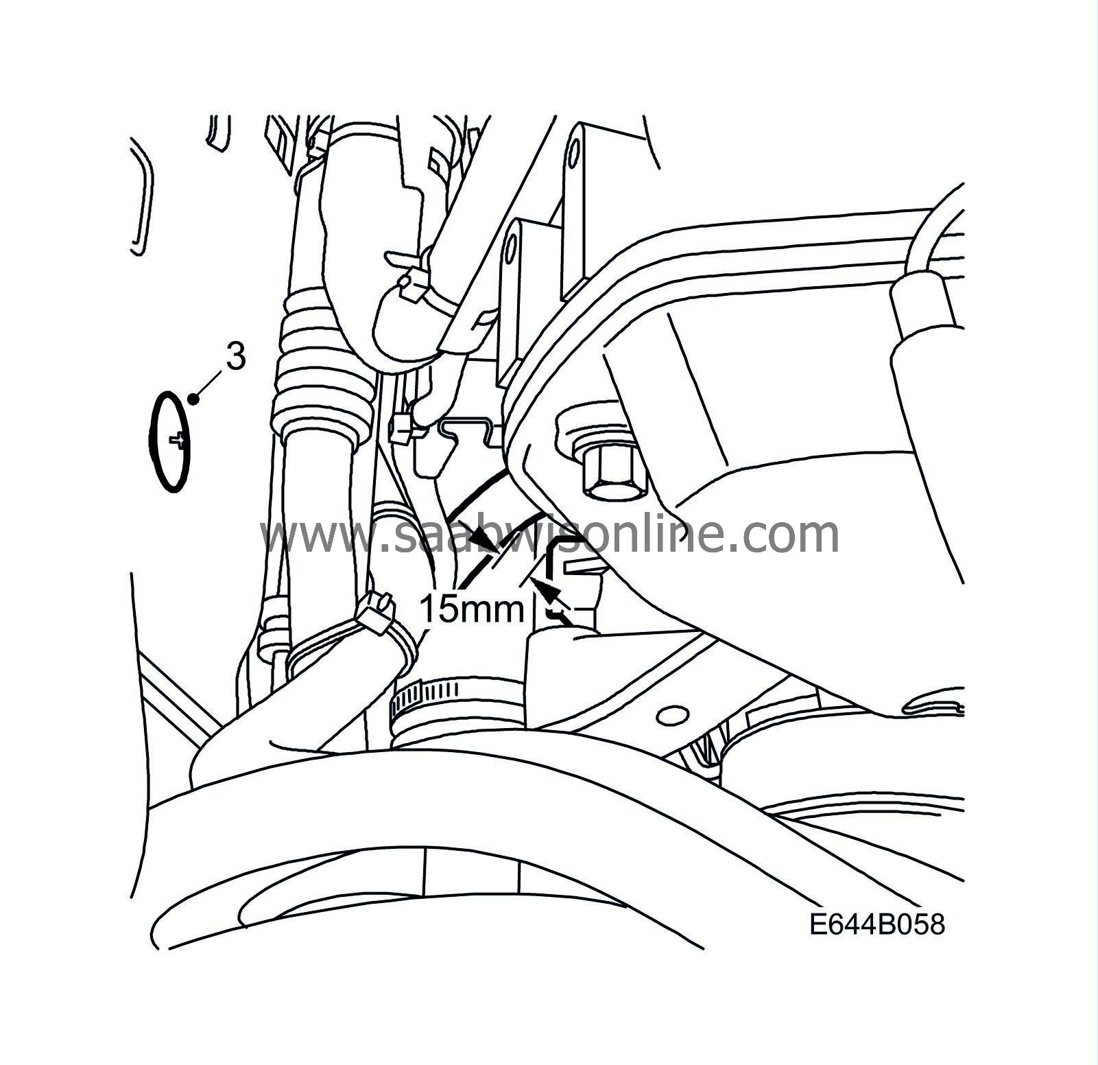
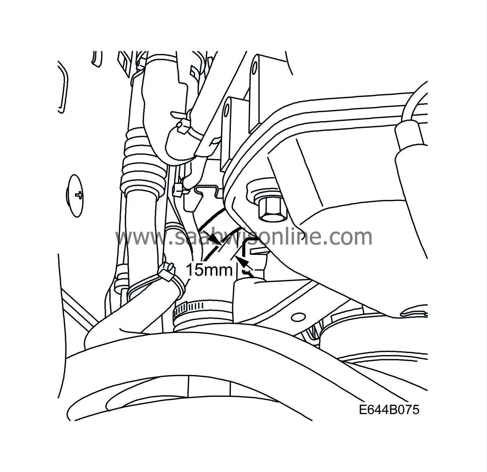
Check the distance between the rear delivery line hose loop and the alternator mounting lug. The distance must be at least 15 mm.
|
|
| 2. |
Is the distance at least 15 mm?
If YES : No procedure is required. If NO : Check the hose for damage. If YES : Replace the line according to "Change of delivery line for power steering" in this MI. If NO : Continue with step 3. |
|
| 3. |
Remove the pressure bolt holding the bulkhead insulation.
|
|
| 4. |
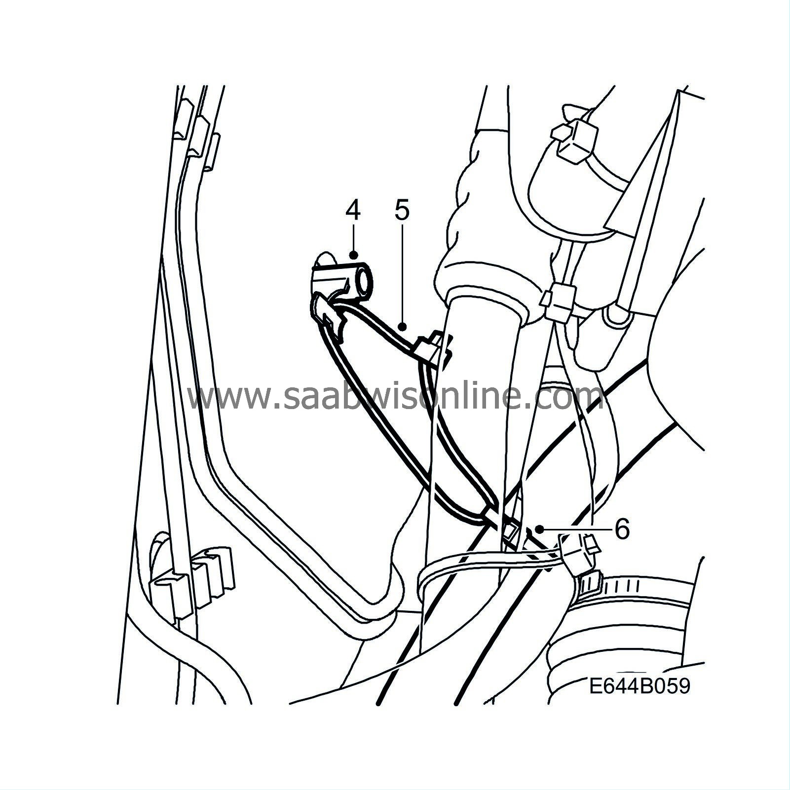
Secure the cable tie mounting, Part No 48 07 939.
|
|
| 5. |
Wrap the short cable tie loosely around the delivery line to the right of the present cable tie.
|
|
| 6. |
Thread the long cable tie through the short cable tie and cable tie mounting.
Tighten the short cable tie around the line. Adjust the distance between the delivery line and the alternator mounting lug to at least 15 mm with the long cable tie. |
|
| Change of delivery line for power steering |
Replace the pipe only if damage has occurred.
Removing
| 1. |
Remove the nut from the rear engine mounting.
|
|
| 2. |
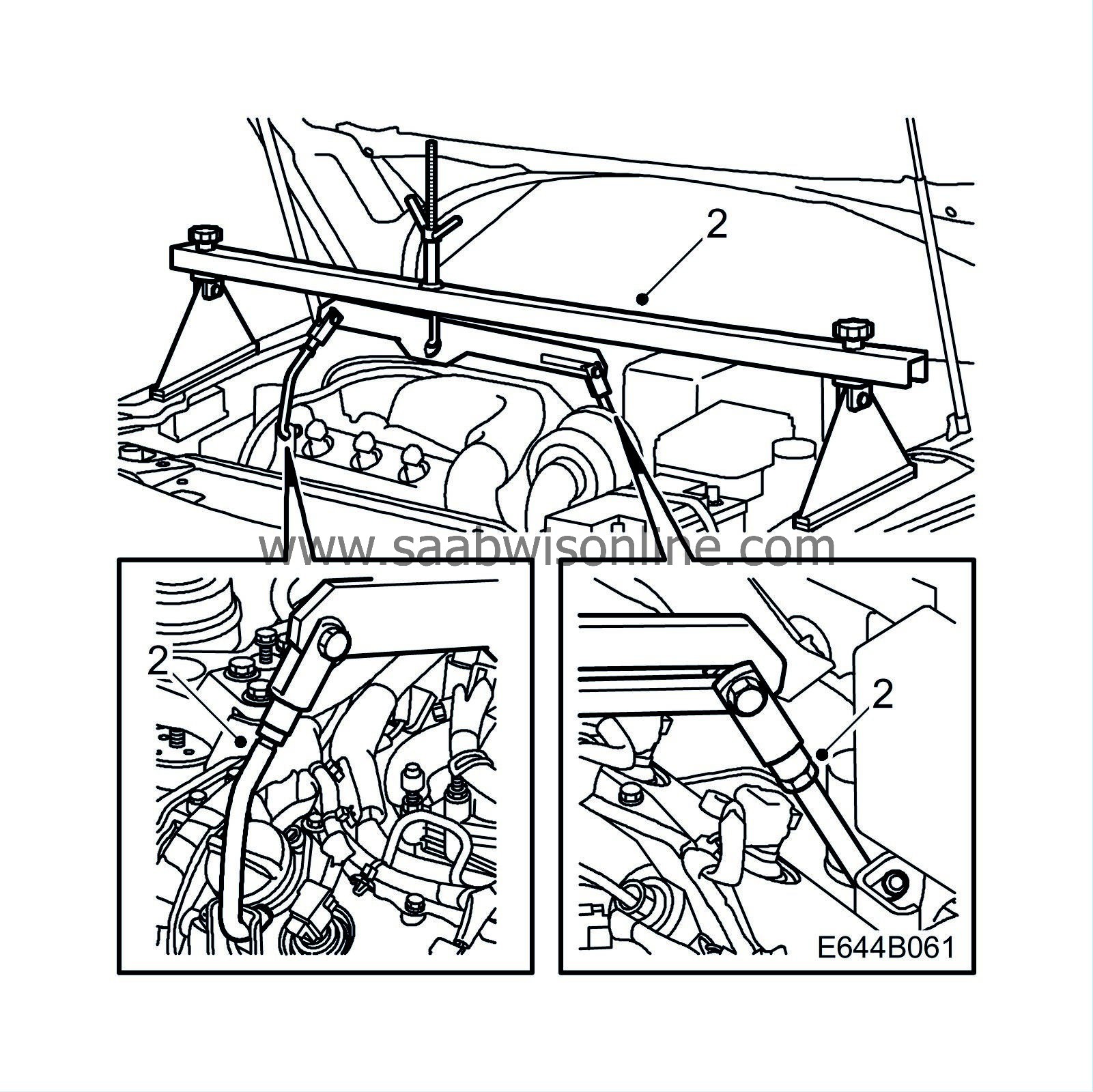
Place 83 94 850 Lifting beam on the wings and fit 83 95 287 Holder in the engine lifting eyes.
|
|||||||
| 4. |
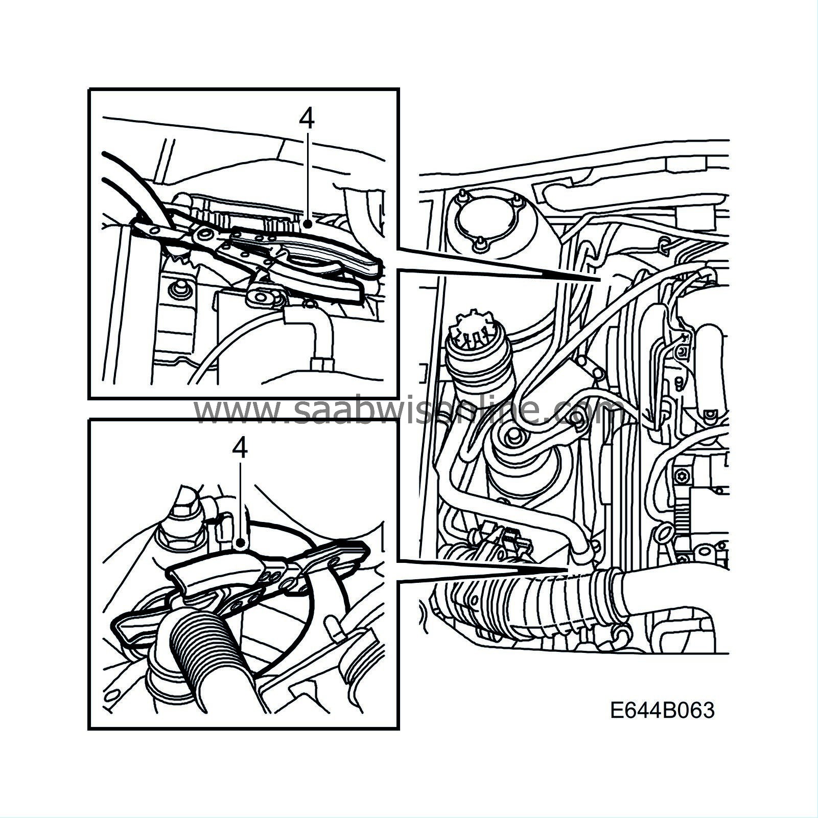
Pinch together the inlet line to the power steering pump and the return line to the reservoir with two 30 07 739 Pinch-off pliers.
|
|
| 5. |
Raise the car.
|
|
| 6. |
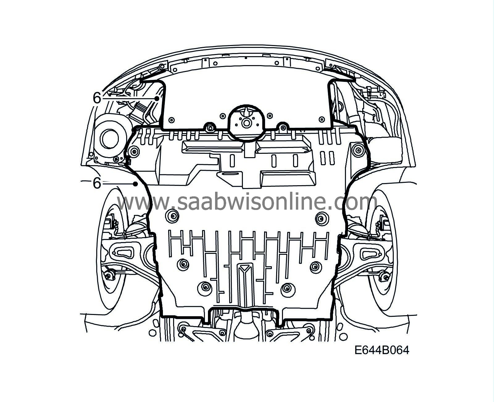
Remove the lower engine cover.
|
|
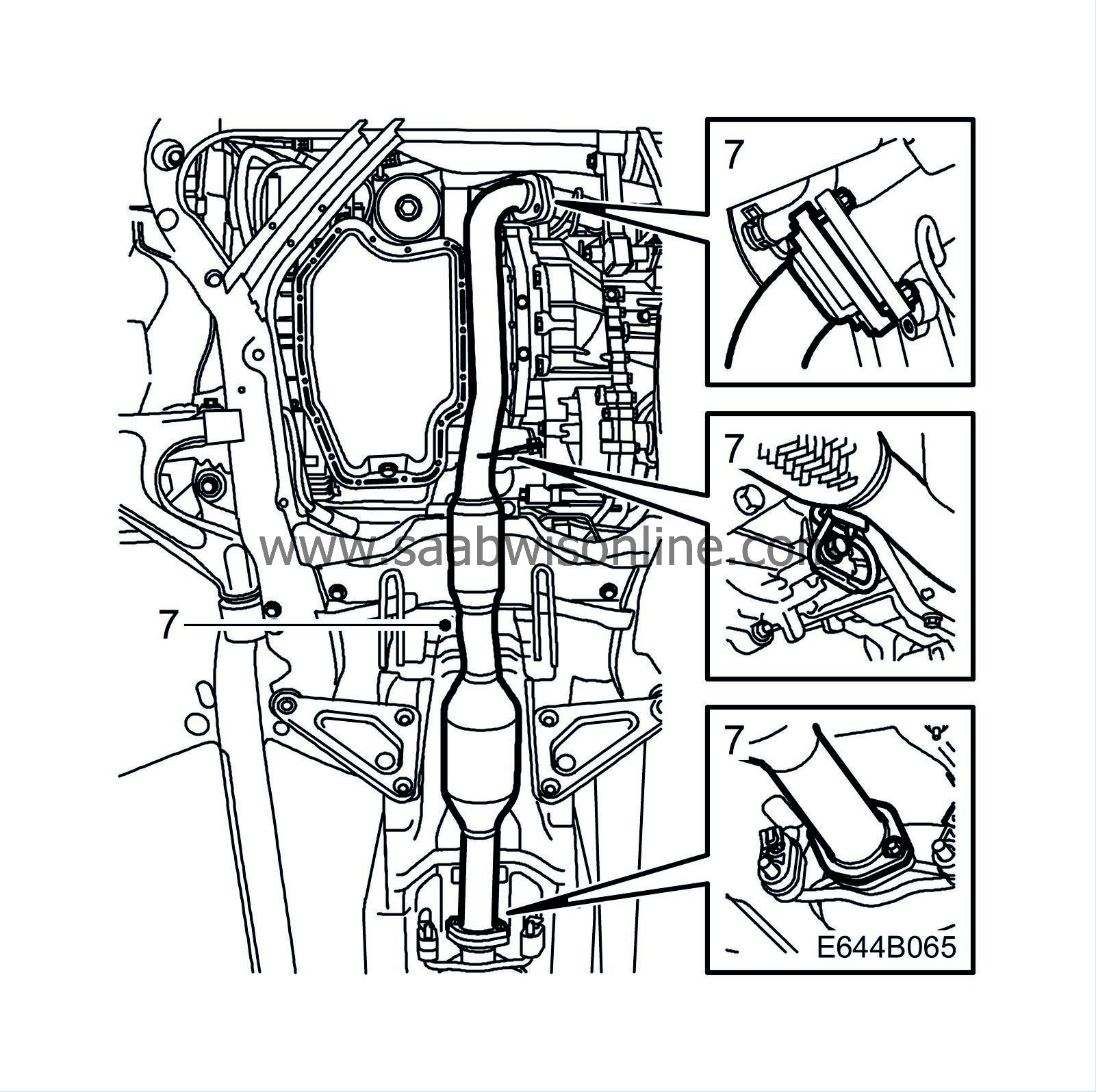
| 7. |
Remove the front exhaust pipe.
|
|
| 8. |
Remove the right wheel and right hand side cover.
|
|
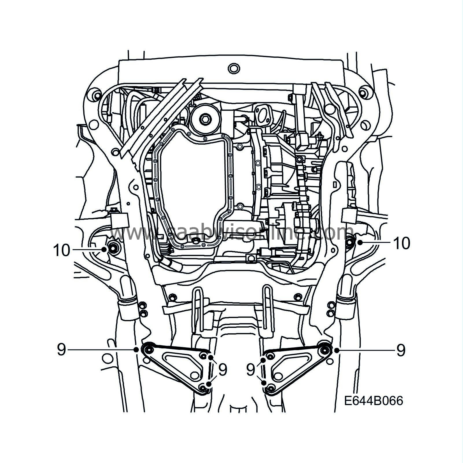
| 9. |
Remove the reinforcement plates.
|
|
| 10. |
Lower the subframe slowly by removing the centre bolts.
|
|
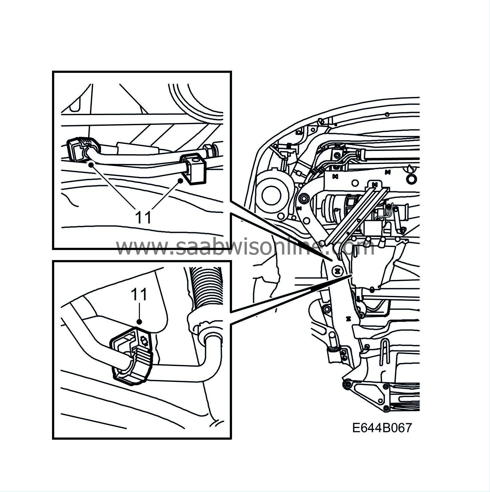
| 11. |
Remove the rear delivery line clips.
|
|
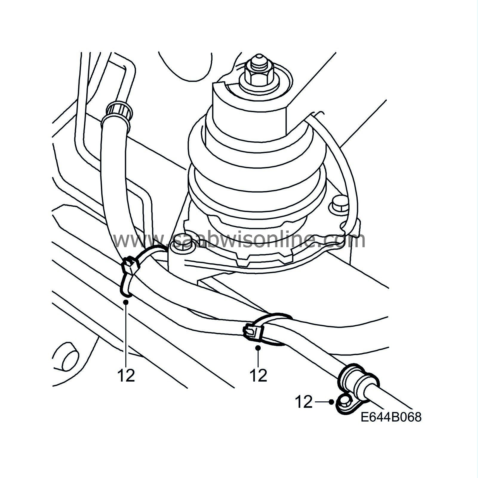
| 12. |
Remove the cable ties and clip holding the pipe to the steering gear.
|
|
| 13. |
Remove the clip holding the rear pipe to the steering gear.
|
|
| 14. |
Place a receptacle under the front pipe joint and unplug the joint.
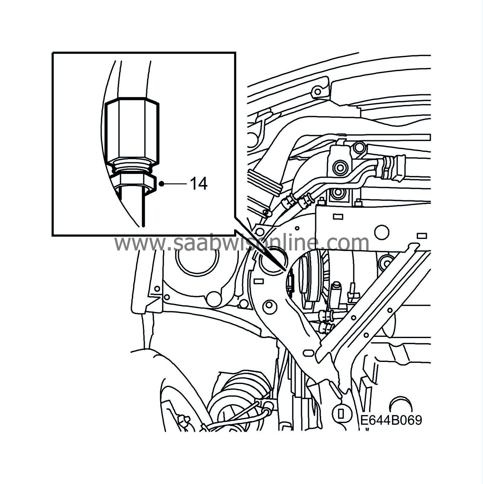
|
|
| 15. |
Place a receptacle under the steering gear and remove the banjo union from the steering gear.
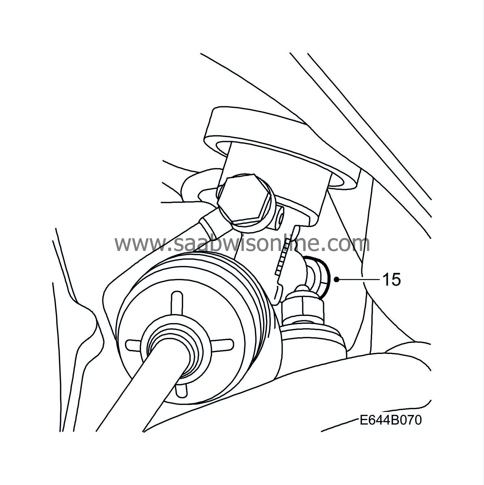
|
|
| 16. |
Remove the pipe.
|
|
To fit
| 1. |
Place the pipe in the proper position starting from the rear.
|
|
| 2. |
Remove the rear transport cover from the new line and insert the banjo union. Use new seals.
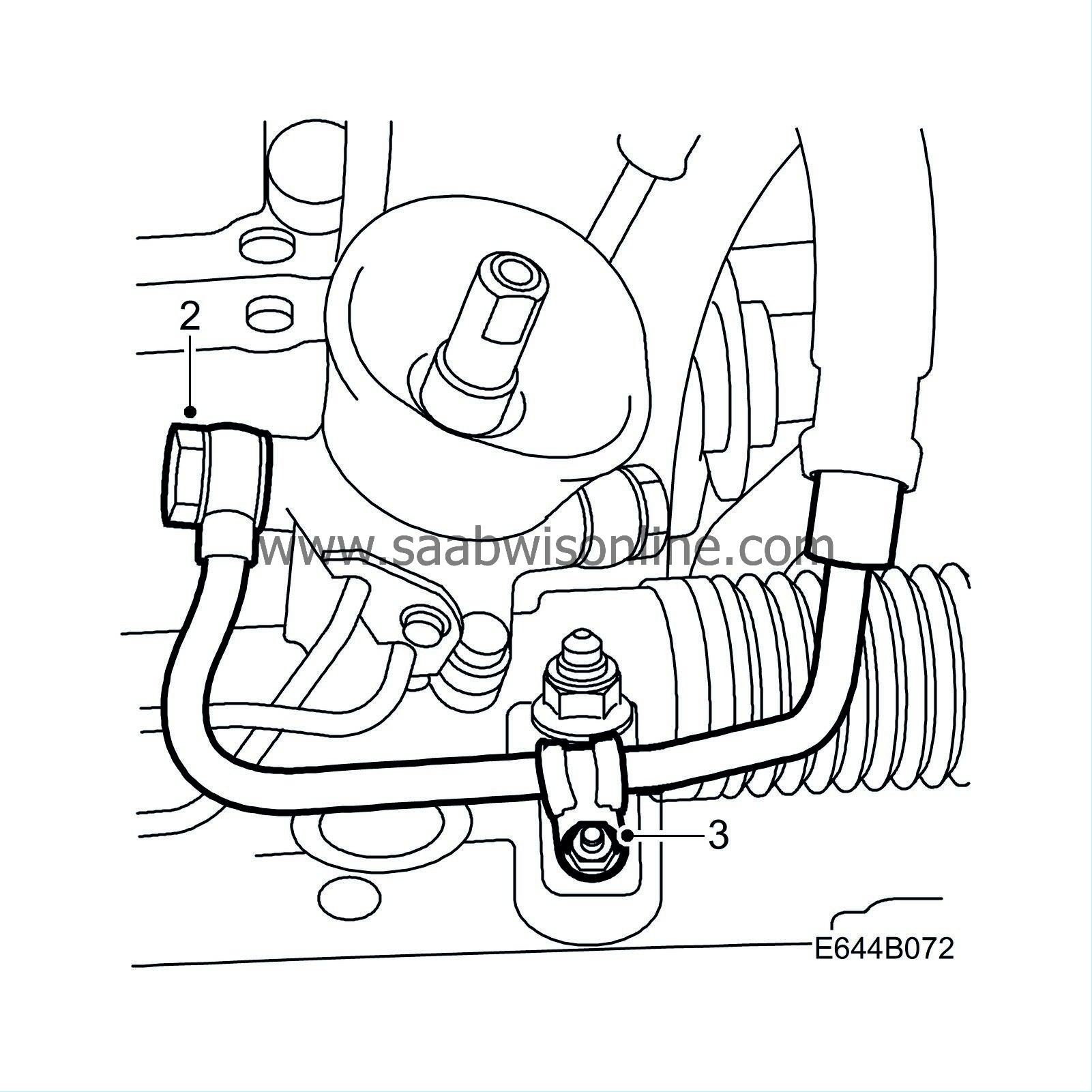
|
|
| 3. |
Fit the rear clip to the steering gear.
|
|
| 4. |
Fit the return line to the delivery line with two cable ties.
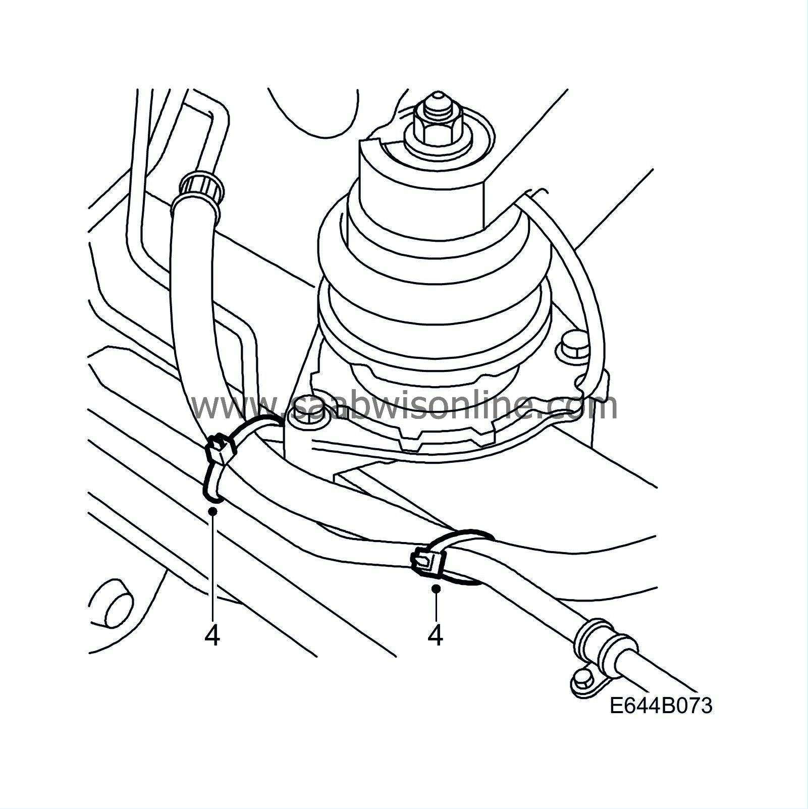
|
|
| 6. |
Check that the seal between the steering gear and body is correctly positioned.
|
|
| 7. |
Lift the subframe high enough so that it comes into contact with the body and tighten the centre screws.
|
|||||||
| 8. |
Check that the distance between the delivery line and the alternator is at least 15 mm.
|
|
| 9. |
Fit the reinforcement plates.
Tightening torque 65 Nm (48 lbf ft) 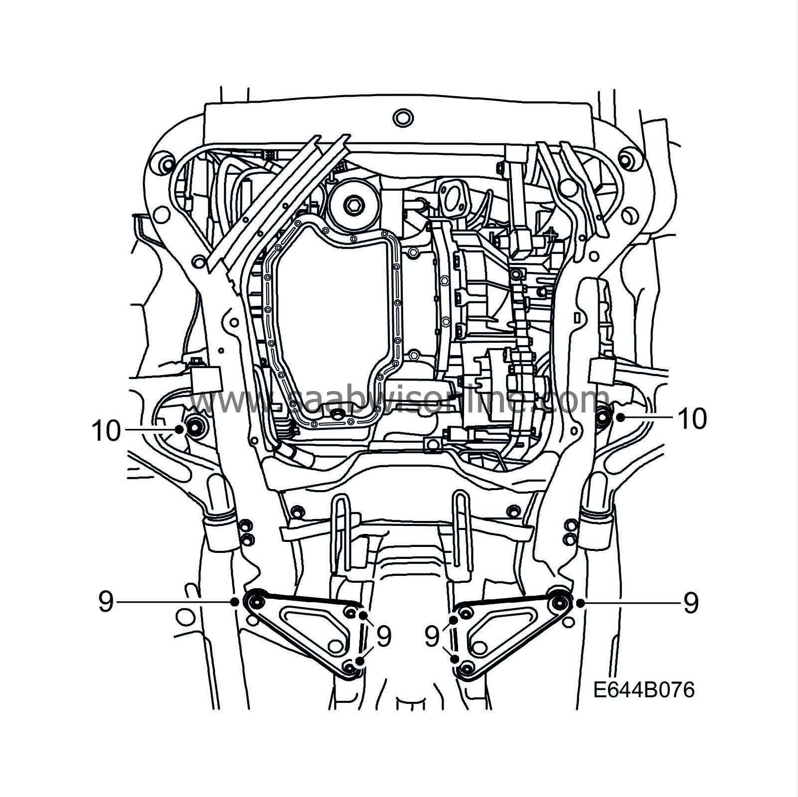
|
|
| 10. |
Tighten the subframe mounting screws.
Tightening torque 100 Nm +45°(74 lbf ft +45°) |
|
| 11. |
Fit the front exhaust pipe.
Fit the mounting. Tighten the nuts on the rear flange. Tightening torque 22Nm (16 lbf ft)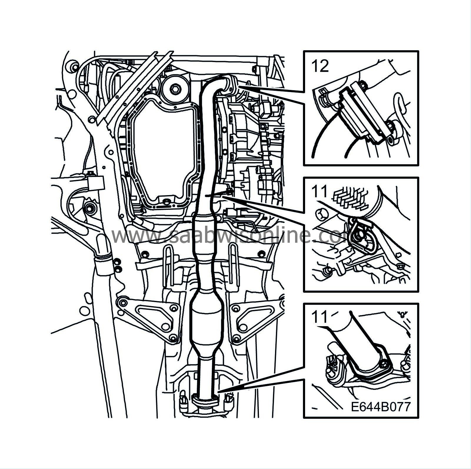
|
|||||||
| 12. |
Tighten the nuts on the front exhaust flange.
Tightening torque 40 Nm (30 lbf ft) |
|
| 13. |
Remove the front transport cover from the new line and tighten the front pipe joint from the delivery line.
|
|||||||
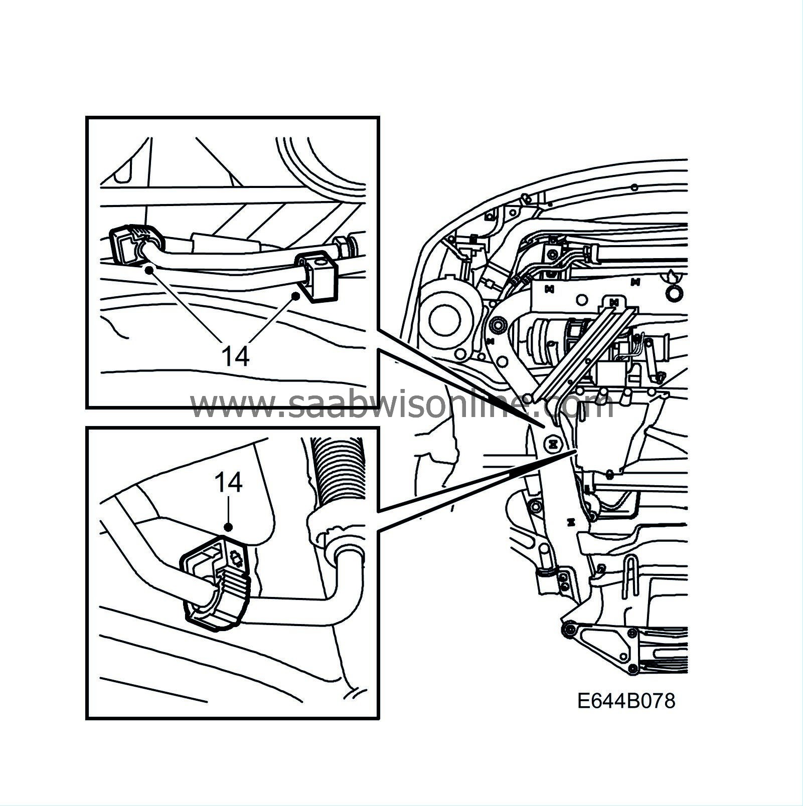
| 14. |
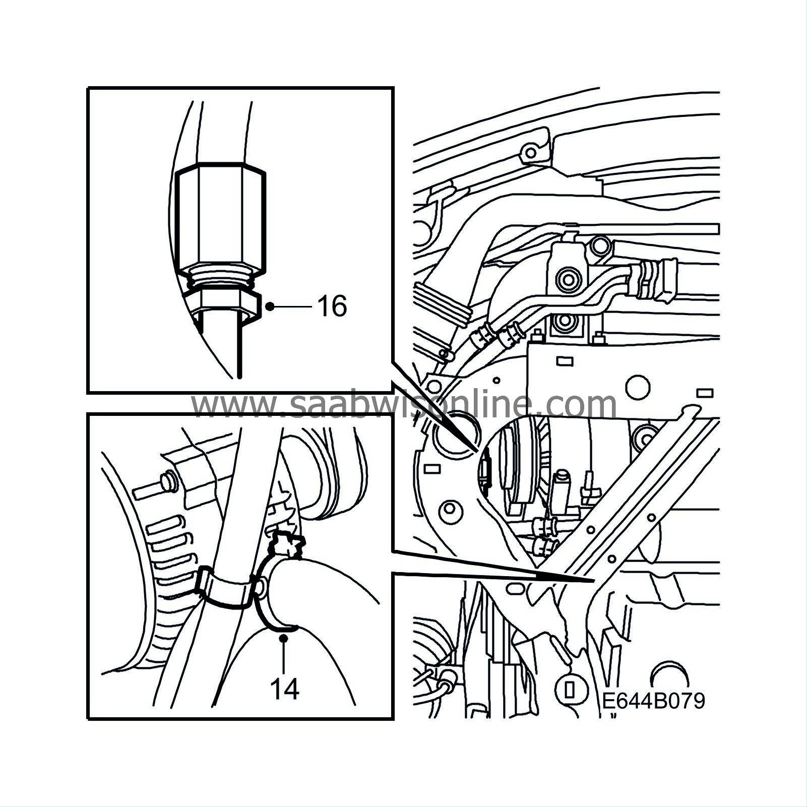
Fit the delivery line clips.
|
|
| 15. |
Fit the plastic support between the delivery line and return line.
|
|
| 16. |
Tighten the front pipe joint. Check that the rear delivery pipe hose connection is at least 5 mm from the subframe.
|
|
| 17. |
Fit the right hand side cover.
|
|
| 18. |
Fit the lower engine cover.
|
|
| 19. |
Lower the car to the floor.
|
|
| 20. |
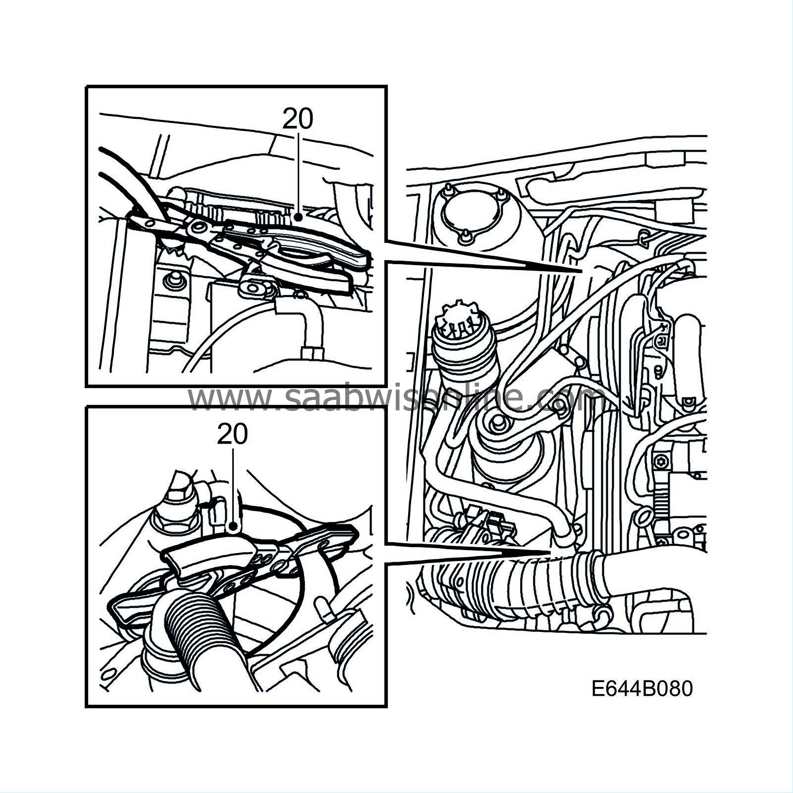
Remove the pinch-off pliers.
|
|
| 21. |
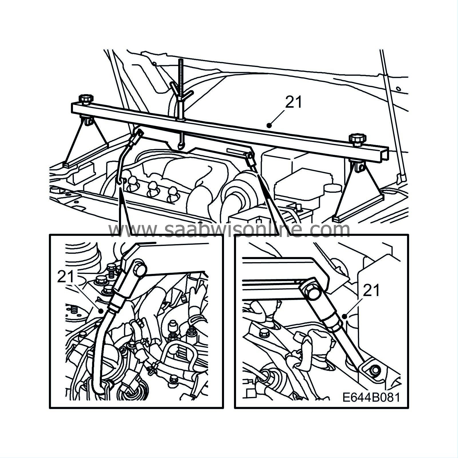
Remove the lifting beam.
|
|
| 22. |
Fit the nut on the rear engine mounting.
Tightening torque 50 Nm (37 lbf ft) |
|
| 24. |
Fill with oil and bleed according to Bleeding power steering system.
|
|
| 25. |
Check for any leakage from hose connections.
|
|
| 26. |
Test drive. Check that the steering wheel is straight. Adjust if necessary.
|
|
| Marking the modification identity plate |
Mark box B4 on the modification identity plate after completed procedures according to MI 248-2318, MI 260-2316, MI 644-2319 (LHD) and MI 644-2230 . If the procedure has been performed by an importer, mark the box "7". Mark with "8" if the procedure has been performed by a dealer.
| Standard time/Warranty information |
See separate information.

