(854-2578) ACC/MCP has difficulty controlling and maintaining the temperature on the passenger side
Symptom: ACC/MCP has difficulty controlling and maintaining the temperature on the passenger side.
|
TECHNICAL SERVICE BULLETIN
|
|
Bulletin Nbr:
|
854-2578
|
|
Date:
...........
|
April 2006
|
|
Market:
|
all
|
|
|
ACC/MCP has difficulty controlling and maintaining the temperature on the passenger side
|
Saab 9-5 M98-04
LHD:
up to and including M04 Vehicle Identification Number 43010216
RHD:
up to and including M04 Vehicle Identification Number 43013832
including those updated with 53 35 831(CA: 30591598) / 53 36 664 (CA: 30592689) Service kit, Heat exchanger housing LHD or 53 35 823/53 36 672 Service kit, Heat exchanger housing RHD in accordance with TSB 854-2396 ed. 2 or TSB 854-2411 ed. 2.
The air mixing damper (heater damper) shaft may fail at which temperature control operates unsatisfactorily or not at all. In addition, temperature control in the rear seat may be affected. The nature of the failure may be such that the problem is intermittent.
The diagnostic trouble codes B2295 and B2495 may be generated.
In many cases the air mixing damper shaft is only broken in the area from the outer end closest to the stepping motor to 30-40 mm in toward the damper, and can then be repaired using this method. Consequently, repairs in accordance with TSB 854-2411 ed. 2 (US/CA) or 854-2396 ed. 2 (other markets) respectively are not necessary.
In the case of customer complaint the air mixing damper shaft must be checked in accordance with the following method.
Symptom description
ACC/MCP has difficulty controlling and maintaining the temperature on the passenger side.
47 57 217 (CA: 30569791) Clip (if necessary)
53 34 701 (CA: 30590472)Lever (if necessary)
12 765 865 Insert sleeve LH, RHD
12 765 867 Insert sleeve RH, LHD
|
1.
|
Clear any diagnostic trouble codes using Tech2.
|
|
3.
|
Select panel setting on the ACC panel. Check that the panel vents are in the open position.

|
|
4.
|
Wait until the system has stabilised (approx. 30 seconds) and then set the temperature to LO on both the driver's and passenger side.
|
|
5.
|
Use your hand to check that air is flowing from the panel vents.
|
|
6.
|
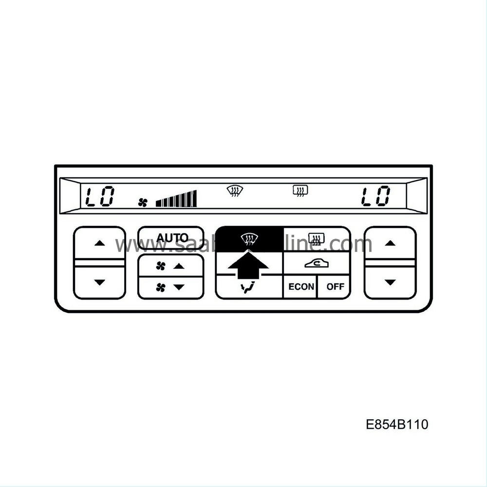
Select defroster setting.
|
|
7.
|
Wait until the system has stabilised (approx. 30 seconds) and then use your hand to check that air is flowing from the vents above the dashboard.
|
|
8.
|
Repeat the check in accordance with steps 3-7.
|
|
9.
|
If the air flow is changed, continue in accordance with step 10.
If the air flow is not changed but still blows from the same air vents then the fault is in the air distribution damper. For remedy see TSB 854-2461 (US/CA) or TSB 854-2450 (other markets) respectively. Switch off the engine.
|
|
10.
|
Allow the engine to run until the coolant thermostat has opened.
|
|
11.
|
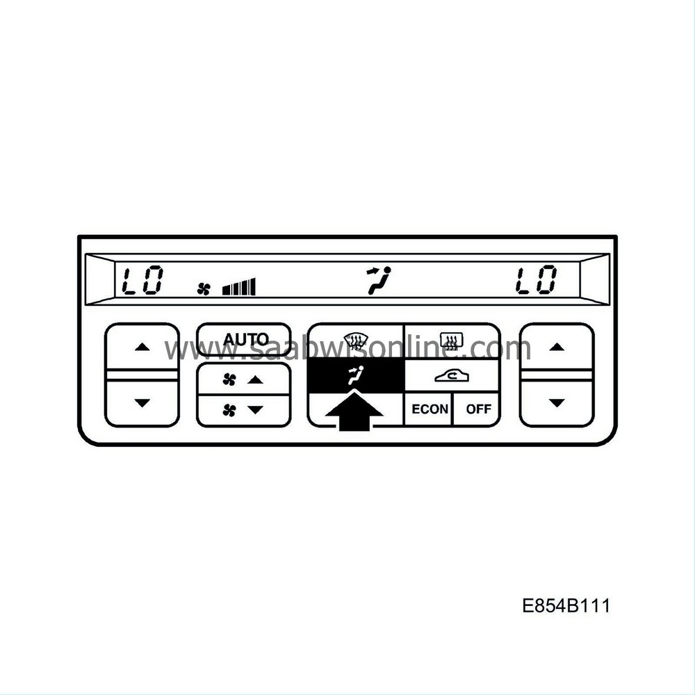
Select panel setting and wait until the system has stabilised (approx. 30 seconds). The panel vents must remain in open position.
|
|
12.
|
Check that the temperature for the driver and passenger is still set to LO.
|
|
13.
|
Use your hand to check that cold air is flowing from all panel vents.
|
|
14.
|
Set the temperature for the driver and passenger to HI.

|
|
15.
|
Select panel setting. Wait until the system has stabilised (approx. 30 seconds).
|
|
16.
|
Use your hand to check that hot air is flowing from all panel vents.
|
|
17.
|
Repeat until the side on which the air cannot be controlled is detected. Switch off the engine.
|
|
18.
|
If the heat cannot be controlled on the passenger side, continue as follows.
If the heat cannot be controlled on the driver's side, see TSB 854-2577.
|
|
19.
|
Turn the ignition key to the ON position.
|
|
20.
|
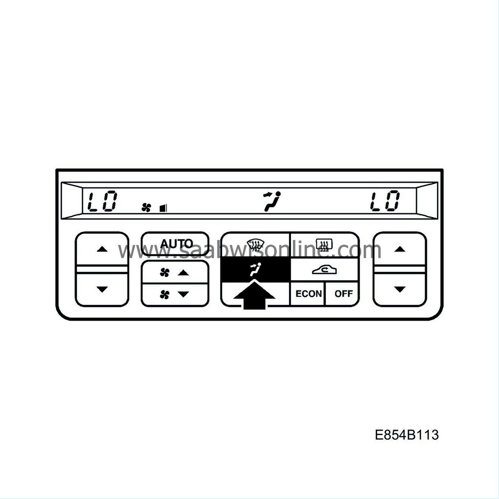
Select panel setting.
|
|
21.
|
Set the temperature for the driver and passenger to LO.
|
|
22.
|
Reduce fan speed to one bar. Wait until the system has stabilised (approx. 30 seconds).
|
|
23.
|
Turn the ignition key to the OFF position.
|
|
24.
|
Remove the glove box in accordance with WIS - Body - Interior equipment - Adjustment/Replacement - Glove box.
|
|
25.
|
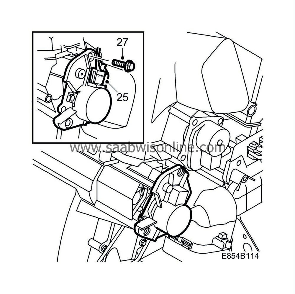
Unplug the lower stepping motor connector (air mixing damper).
|
|
26.
|
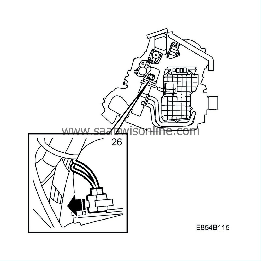
Remove the mixed air temperature sensor.
|
|
27.
|
Remove the stepping motor.

|
|
28.
|
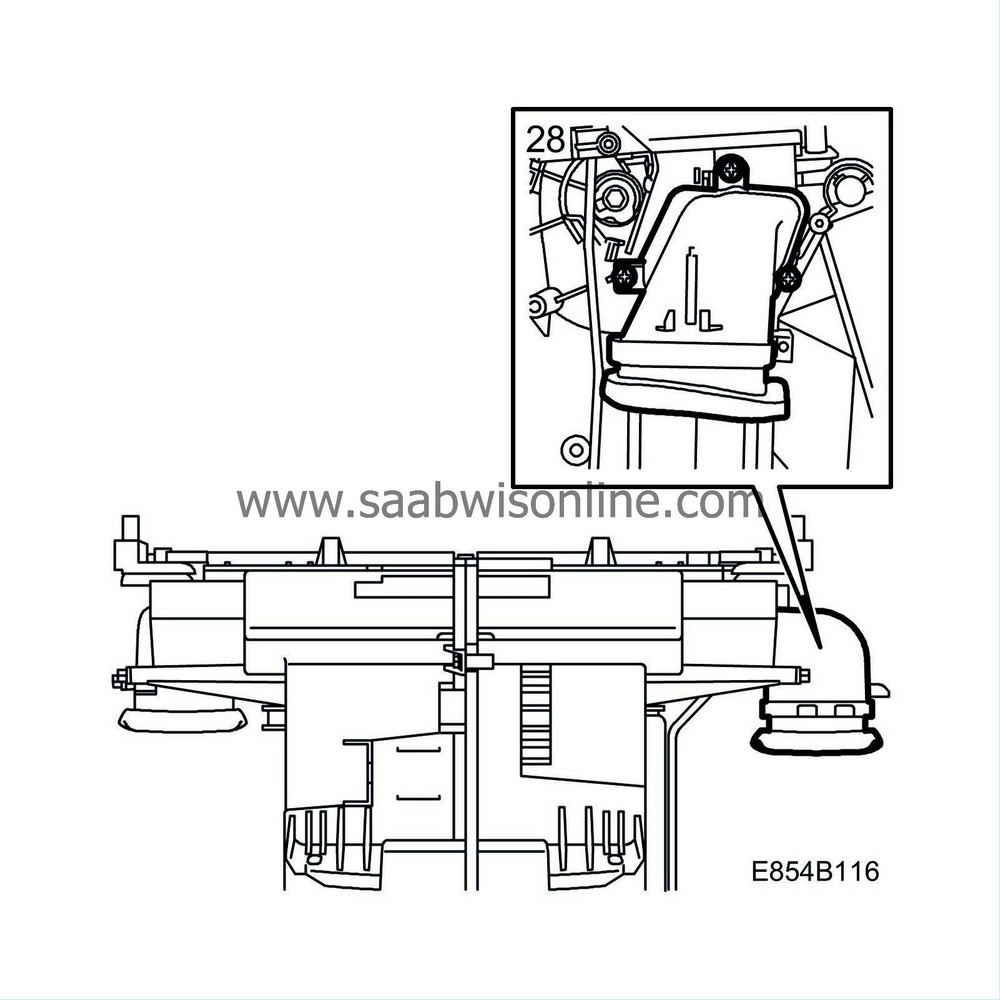
Remove the air duct from the heating and ventilation unit.
|
|
29.
|
Check whether and where the air mixing damper shaft is ruptured (by using a mirror). Wipe away any grease to see properly.
|
|
30.
|
If the shaft is not broken then check the function of the stepping motor (detached motor) using Tech2 (the "Activate" menu).
|
|
|
•
|
If the shaft and stepping motor are in working order then check whether the heat can be controlled manually by rotating the shaft manually (with the engine running).
|
|
|
•
|
If the heat cannot be controlled then the air mixing damper further inside the heating and ventilation unit may itself be broken. For further fault diagnosis see TSB 854-2411 ed. 2 (US/CA) or TSB 854-2396 ed. 2 (other markets) respectively.
|
|
31.
|
If the shaft is broken in accordance with A in the illustration then the sleeve cannot be used. For further repair see TSB 854-2411 ed. 2 (US/CA) or TSB 854-2396 ed. 2 (other markets) respectively.

|
|
32.
|
If the shaft is broken in accordance with B or C in the illustration then the sleeve can be used. Continue as follows.
|
|
33.
|
Remove the upper section of the control rod to the rear air mixing damper.
|
|
34.
|
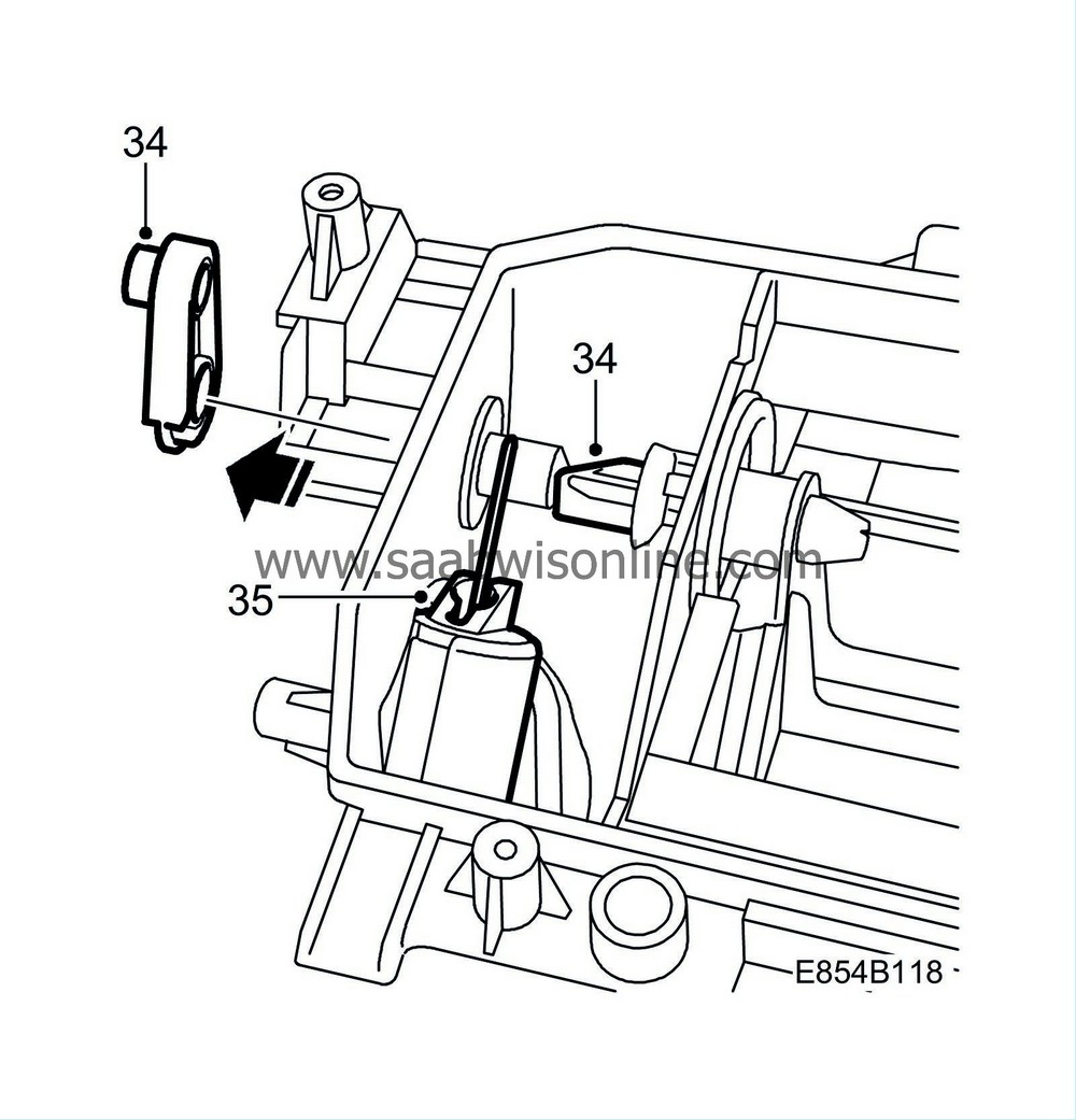
Remove the lever if it is still on the air mixing damper shaft.
|
|
35.
|
Try to rotate and press the broken section that is closest to the stepping motor into the car and then try to remove it from the heating and ventilation unit.
If this does not work, use a pneumatic saw and cut the section closest to the stepping motor as far out in the car as possible.
|
Note
|
|
Take care that the section of the shaft to remain in the car is not damaged.
|
|
|
36.
|
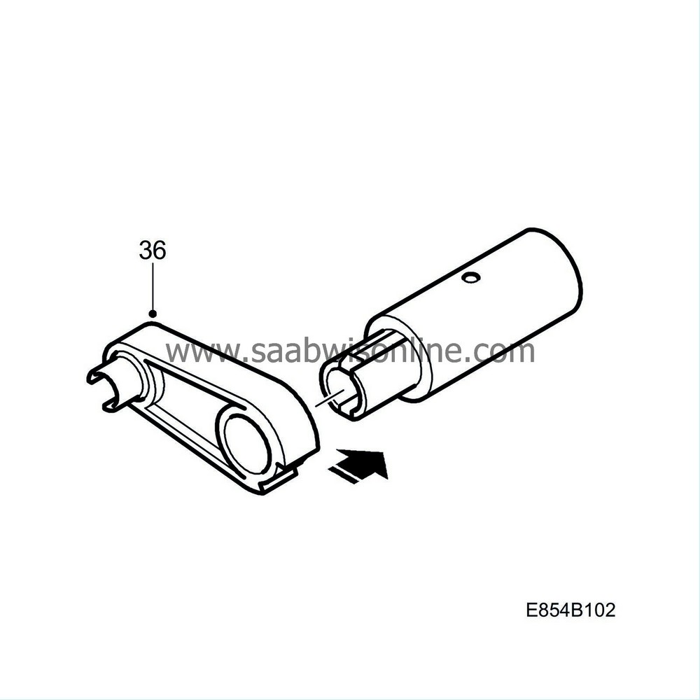
If the lever is damaged then fit a new lever and clip on sleeve 12 765 865 (RHD) or 12 765 867 (LHD), otherwise fit the existing lever on the respective sleeve. The small radius of the lever must be aimed backward in the car.
|
Note
|
|
Keep the sleeve's locking catch held upward when the lever is pressed. Check that the locking catch secures the lever.
|
|
|
37.
|
Depending on where the break is located on the shaft and on cars with Vehicle Identification Number from and including 23051858 (LHD) or 230519440 (RHD) respectively casting residue may need to be cut off with a knife.
|
|
|
-
|
The casting residue is located on the rear of the long shaft, approx. 40 mm from the outer end. Feel with your fingers or use a mirror to locate the casting residue.
|
|
|
-
|
Rotate the shaft anticlockwise and position a knife above the shaft with the cutting edge in toward the car. Cut the casting residue away carefully.
|
|
38.
|
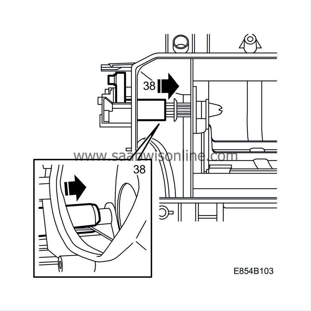
Hold a finger as counterhold on the U-shaped section of the shaft and carefully press the new sleeve in. Rotate so that the socket aligns into the shaft.
|
|
39.
|
Check the function by rotating the lever from one end position to the other.
|
|
40.
|
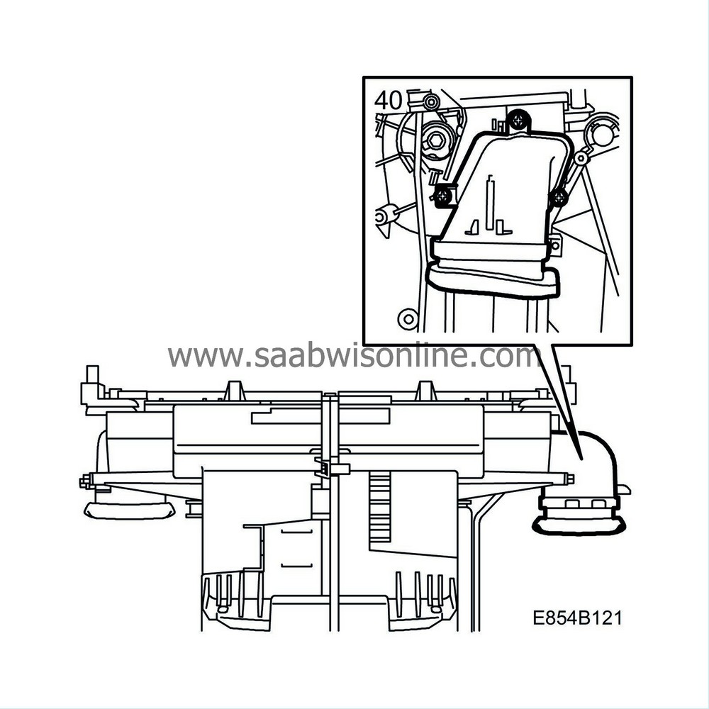
Fit the air duct on the heating and ventilation unit.
|
|
41.
|
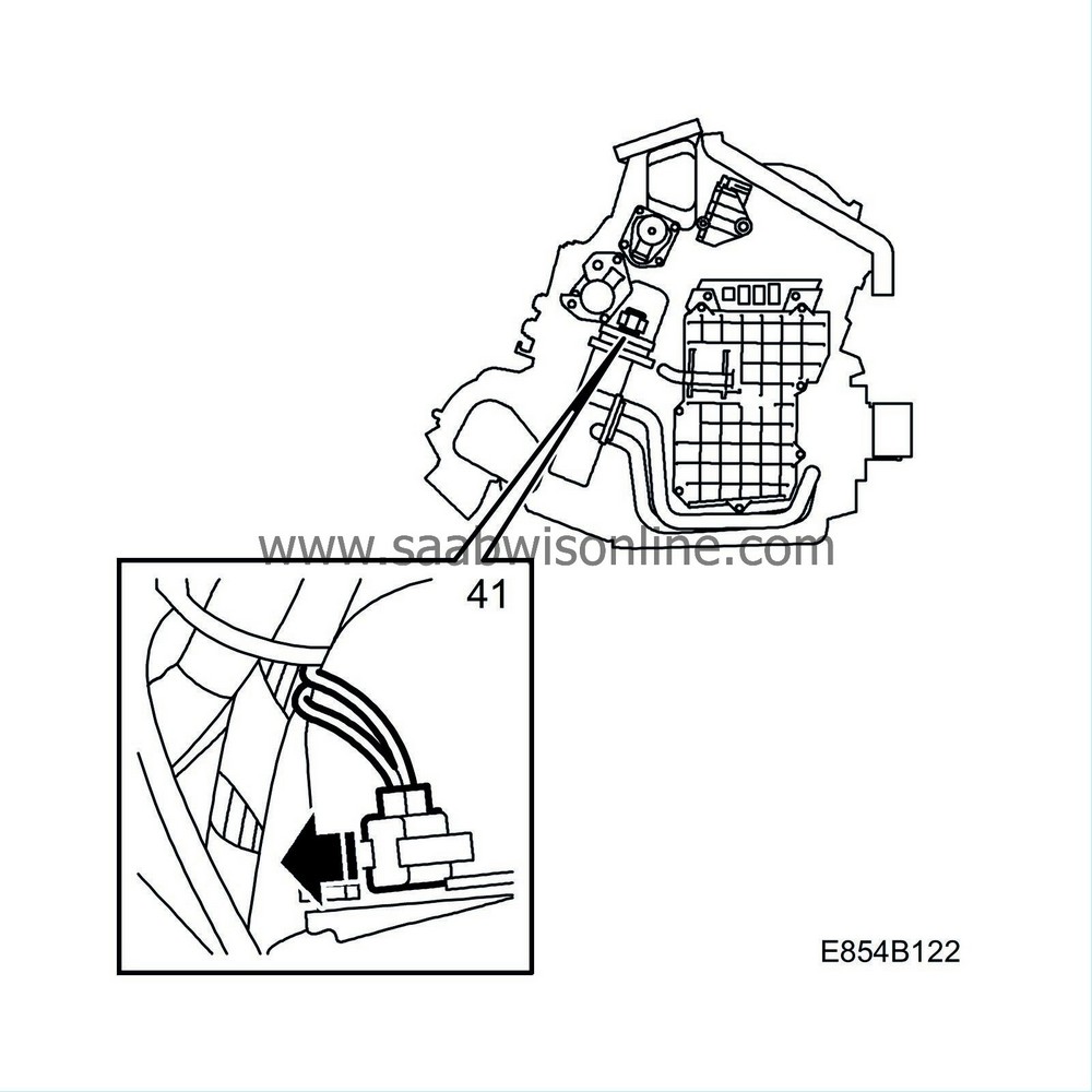
Fit the mixed air temperature sensor.
|
|
42.
|
Fit the upper section of the control rod to the rear air mixing damper.
|
|
43.
|
Plug in the stepping motor connector for the air mixing damper.

|
|
44.
|
Fit the stepping motor. If the motor shaft does not fit then rotate it carefully to the correct position using pliers.
|
|
46.
|
Wait to see whether the ACC system calibrates itself. Otherwise, calibrate the ACC system by simultaneously depressing the AUTO and OFF buttons.
|
|
47.
|
Wait until system calibration is complete (approx. 30 seconds) and then set the temperature to LO on both sides and select AUTO.
|
|
48.
|
Wait until the system has stabilised (approx. 30 seconds). Use your hand to feel whether cold air is flowing from all panel vents.
|
|
49.
|
Set the temperature to HI on both sides and select panel setting.
|
|
50.
|
Wait until the system has stabilised (approx. 30 seconds). Use your hand to feel whether hot air is flowing from all panel vents.
|
|
51.
|
Set 21 on both sides. Wait until the system has stabilised (approx. 30 seconds).
|
|
52.
|
Fit the glove box in accordance with WIS - Body - Interior equipment - Adjustment/Replacement - Glove box.
|
|
53.
|
Clear any diagnostic trouble codes.
|
|
Warranty/Time Information
|
In the case of customer complaint and if the car is
within the warranty period
, use the following information to fill out the claim:
Failed Object: 85434
Fault/Reason code: 71
Location code: 09 (US=4 Right/Passenger Side)
Warranty Type (US): 01
Repair/Action code: 01
Labour Operation (US): 8543403
Labour Operation (CA): D0580
Time: 0.7 hr


