Solar sensor
| Solar sensor |

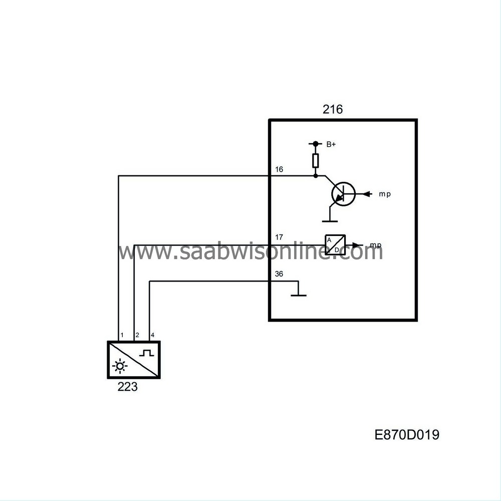
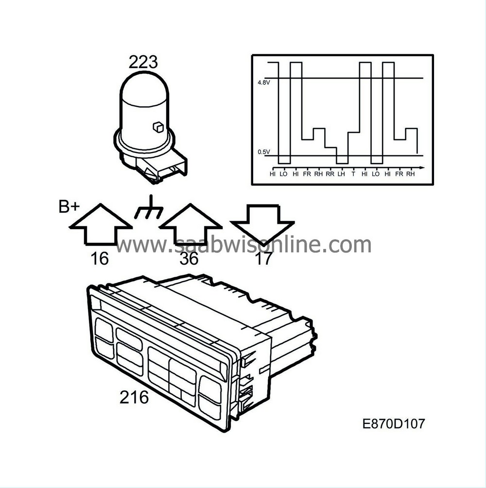
The solar sensor, located at the top of the dashboard, contains 5 solar cells: LH, RH, front, back and top. The plastic housing is coloured so that only infrared light (heat radiation) can penetrate. The solar sensor is fed B+ pulses from pin 16 and is grounded via pin 36. Voltage from the 5 sensor elements is sent in sequence to pin 17 of the ACC unit.
For the control module to be able to identify which solar cell is reporting, each transmission is begun with the pulse pattern 5 V - 0 V - 5 V. The control module synchronises the solar sensor pulse transmissions by sending short ground pulses of 25 Hz from pin 16.
The control module uses the voltage from the 5 solar cells to calculate the sun's intensity, bearing and height.
The values are used to calculate the current temperature at head height for the front seat passenger and driver. The following are also used as default values:
| • |
outside temperature
|
|
| • |
time since engine last ran
|
|
| • |
time since start
|
|
| • |
blended-air temperatures
|
|
| • |
fan speed
|
|
The calculated temperatures are compared to those the driver and passengers have set on the ACC unit display. The set temperature is adjusted with respect to the outside temperature so that the perceived temperature corresponds with the set temperature.
As soon as a difference occurs, the blended-air temperature must be increased or decreased. The control module turns the air-blending flap in question until the required blended-air temperature is achieved.
Adjustment
Using the diagnostics tool, the ACC unit can be adjusted to include a larger or smaller proportion of the solar sensor value when calculating the cabin temperature.| Diagnostics |
In the event of an open circuit or short circuit, diagnostic trouble code B1340 is set and 03 is displayed instead of right-hand temperature when calibrating. The latest valid value is used as a default value. When the ignition is turned on, 0 W/m 2 is used.


