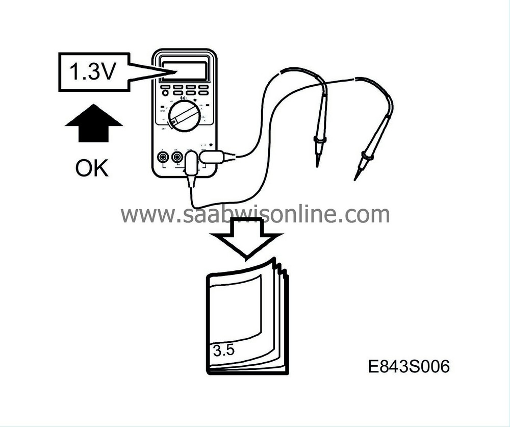
Test readings, control module connections
|
|
Test readings, control module connections
|
The following pages contain values and instructions for obtaining readings of signals and levels on the control module.
|
•
|
Note the test conditions and use your common sense when judging the test results.
|
|
•
|
First check that the control module is supplied with current and grounded.
|
|
•
|
Then check all sensor inputs and signals from other systems.
|
|
•
|
Check the control module outputs last. Remember that the test readings do not indicate whether or not the actuator is working.
|
|
•
|
If any reading is not OK, consult the wiring diagram to trace the leads, connectors or components which ought to be checked more thoroughly.

|
|
•
|
The test readings given apply to a correctly calibrated Fluke 88/97.
|
|
•
|
The readings indicate the pulse ratio and pulse duration of the signal. A test instrument capable of measuring both pulse ratio and pulse duration must be used. The + sign denotes a positive trigger pulse (TRIG+).
|

|
Pin
|
Component/Function
|
In/Out
|
Test conditions
|
Between X and Y
|
Measurement value (V)
|
1
|
Power supply +30
|
In
|
|
1-8
|
B+
|
2
|
Power supply (+15 circuit)
|
In
|
Ignition ON
|
2-8
|
B+
|
3
|
Switch, downward angling
|
In
|
Ignition ON
Button in neutral
Button pressed in
|
3-8
|
B+
< 0,5
|
4
|
Power supply, potentiometers, left door
|
Out
|
Ignition ON
|
4-8
|
4-6
|
5
|
Power supply, potentiometers, right door
|
Out
|
Ignition ON
|
5-8
|
4-6
|
6
|
Ground, potentiometers, left door
|
In
|
Ignition ON
|
6-fuse grounding point
|
< 0,5
|
7
|
Ground, potentiometers, right door
|
In
|
Ignition ON
|
7-fuse grounding point
|
< 0,5
|
8
|
Ground
|
In
|
|
8-fuse grounding point
|
< 0,5
|
9
|
Potentiometer, horizontel, left door
|
Out
|
Ignition ON
|
9-7
|
0,5-4,5
|
10
|
Potentiometer, horizontel, right door
|
In
|
Ignition ON
|
10-7
|
0,5-4,5
|
11
|
Potentiometer, vertical, right door
|
In
|
Ignition ON
|
11-7
|
0,5-4,5
|
12
|
Potentiometer, vertical, left door
|
In
|
Ignition ON
|
12-7
|
0,5-4,5
|
13
|
Motor, vertical, right door
|
Out
|
Ignition ON
See table

|
13-7
|
B+
< 0,5
|
14
|
Motor, horizontal, right door
|
Out
|
Ignition ON
See table

|
14-7
|
B+
< 0,5
|
15
|
Motor, horizontel, left door
|
Out
|
Ignition ON
See table

|
15-7
|
B+
< 0,5
|
16
|
Motor, vertical, left door
|
Out
|
Ignition ON
See table

|
16-7
|
B+
< 0,5
|
17
|
Motor, common output
|
Out
|
Ignition ON
See table

|
17-7
|
B+
< 0,5
|
18
|
No connection
|
|
|
|
|
19
|
I-Bus (+)
|
In/Out
|
Ignition ON
|
19-8
|
2-3
|
20
|
I-Bus (-)
|
In/Out
|
Ignition ON
|
20-8
|
2-3
|


