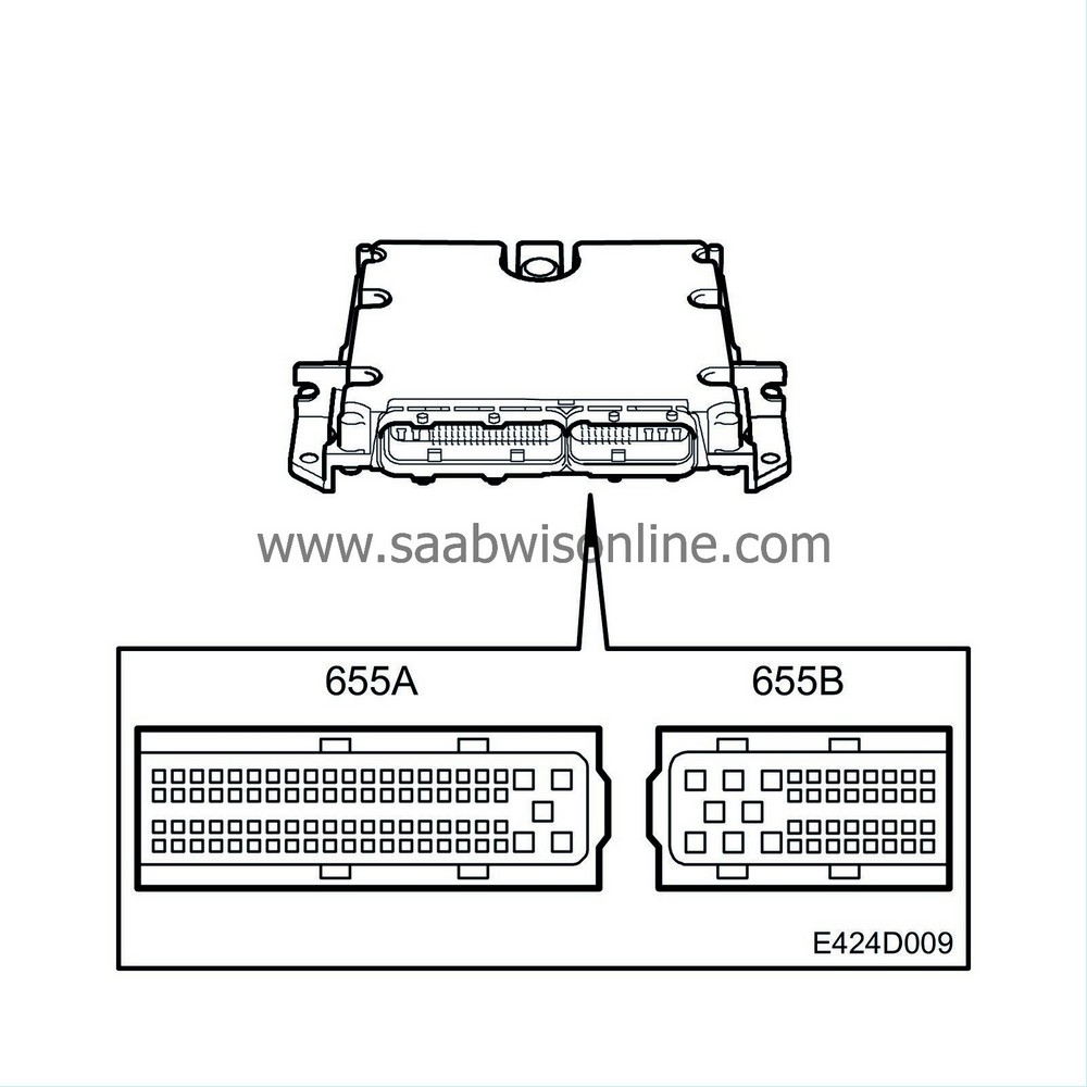
ECM control module
| ECM control module |
The control module fitted in the well (cabin side) in front of the windscreen on the passenger side has two connectors, one 81-pin and one 40-pin.
The control module is powered with +30 on pin 1 and 2 from the main relay, +15 from fuse 27 to pin 24 and +50 from fuse 30 to pin 42. The control module has a running-on function that must complete before the control module stops grounding the main relay.
The running-on function is controlled by DICE via the I- and P-bus and starts when the ignition key is turned to OFF, i.e. the +15 supply on pin 24 ceases. DICE keeps the ECM control module awake (about 40 s) in order to read the engine temperature and control the radiator fan.
The control module has a flash memory and cannot be reprogrammed.
When clearing DTCs, the ignition must be switched off at least 10 seconds and communication with the car via Tech 2 complete before a DTC is finally cleared.
After turning the ignition key to ON, the Check Engine lamp will come on as a function check. If there are no system faults, the lamp will go out again after 3.5 seconds or when the engine has started, whichever occurs first.
Fuel injection is regulated mainly by the pedal position, coolant temperature and engine speed. In case of a fault, there are substitute functions available in the control module for all the sensors.
There is an atmosphere absolute pressure sensor on the control module circuit board.
Atmospheric pressure is used to:
| - |
Correct the PWM ratio of the charge air control valve. At low atmospheric pressure, a greater PWM ratio is required to obtain the same fuel quantity/combustion.
|
|
| - |
Protect the turbocharger from overspeeding in case of low atmospheric pressure by limiting the maximum permissible fuel quantity per combustion.
|
|
| Diagnostics |
If the control module or associated wiring is defective, it can be indicated by the following DTCs:
| • |
If the control module program memory ROM or working memory RAM is defective, DTC P0601 or P0606 will be generated.
|
|
| • |
In the case of a fault in the immobilizer, P1610, P1611, P1613 or P1614 will be generated.
|
|
| • |
If the atmospheric pressure sensor is defective, DTCs P1632-P1633 will be generated. 100 KPa is used as a substitute value and bleeding is blocked.
|
|
| • |
P0148
Fuel Delivery Error.
|
|
| • |
P0301
Cylinder 1 Misfire Detected.
|
|
| • |
P0302
Cylinder 2 Misfire Detected.
|
|
| • |
P0303
Cylinder 3 Misfire Detected.
|
|
| • |
P0304
Cylinder 4 Misfire Detected.
|
|
| • |
P0305
Cylinder 5 Misfire Detected.
|
|
| • |
P0306
Cylinder 6 Misfire Detected.
|
|
| • |
P0512
Starter Voltage (+50) input constant low.
|
|
| • |
P0562
System Voltage Low.
|
|
| • |
P0563
System Voltage High.
|
|
| • |
P1512
Starter Voltage (+50) input constant high.
|
|
| • |
P1608
P-Bus Malfunction. No Bus Data From MIU.
|
|
| • |
P1625
P-Bus Malfunction. No Bus Data From TC/ABS.
|
|
| • |
P1634
Voltage Supply Group 1. Short to Ground.
|
|
| • |
P1635
Voltage Supply Group 1. Short to B+.
|
|
| • |
P1636
Voltage Supply Group 2. Short to Ground.
|
|
| • |
P1637
Voltage Supply Group 2. Short to B+.
|
|
System reaction to a fault
| • |
Engine will not start.
|
|
| • |
Torque reduction.
|
|


