(232-2415) Replacement of air filter housing, reprogramming ECM and fitting of tail pipe, V6 Diesel
Symptom: The functionality of the engine deteriorates due to wetness and clogged filter insert.
|
MODIFICATION INSTRUCTION
|
|
Bulletin Nbr:
|
232-2415
|
|
Date:
...........
|
Oktober 2003
|
|
Market:
|
enl. separat lista
|
|
|
Replacement of air filter housing, reprogramming ECM and fitting of tail pipe, V6 Diesel
|
|
Customer Satisfaction Campaign 154 23
|
Cars in stock must be rectified before delivery.
A personal communication must be sent to the owners of cars already delivered requesting them to get in touch with the nearest Saab garage as soon as possible to have the fault rectified.
Saab 9-5 M02 with engine variant D308L, 130 kW (176 hp), within Vehicle Identification Number range 23000132 - 23058970
When driving in severe wet weather there is a risk of water entering the intake system which can result in deteriorating engine functionality. In order to prevent water from entering into the intake system an air filter housing with water separator is fitted. It is essential that the car is updated with new software designed for the new air filter housing.
In addition, the new software for the V6 diesel engine management system has been improved in a range of areas, including:
|
-
|
reduction of vibrations and jerking at low engine speed and light load
|
|
-
|
reduction of jerking at high engine speed and light load
|
|
-
|
reduction of black smoke with acceleration
|
|
-
|
performance at starting
|
In order to reduce the blackening of the rear bumper shell, a new tail pipe is fitted on the exhaust pipe.
Symptom description
The functionality of the engine deteriorates due to wetness and clogged filter insert.
54 64 086 Air filter housing complete
50 48 681 A/C pipe
16 - 47 59 106 Compressor oil (12 pcs per package, sufficient for 6 cars)
54 65 943 Chafing guard
Refrigerant
Anti-corrosion primer 1K Primer Filler, or similar
53 38 231 Tail pipe
83 36 406 Clamp
Before proceeding, check box D4 of the modification identity plate. If the box is not marked, continue as follows.
The precondition for this MI is that MI 410-2372, 232-2370, 210-2365 and 248-2404 have been carried out.
|
1.
|
Drain the A/C system, see WIS 9-5 M02 - 8. Body - Heating and Ventilation, A/C - Adjustment/Replacement - Draining and filling of refrigerant.
|
|
2.
|
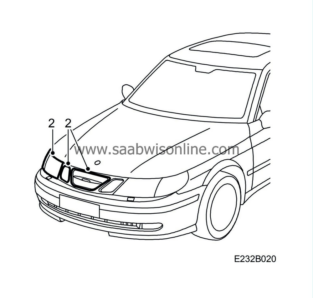
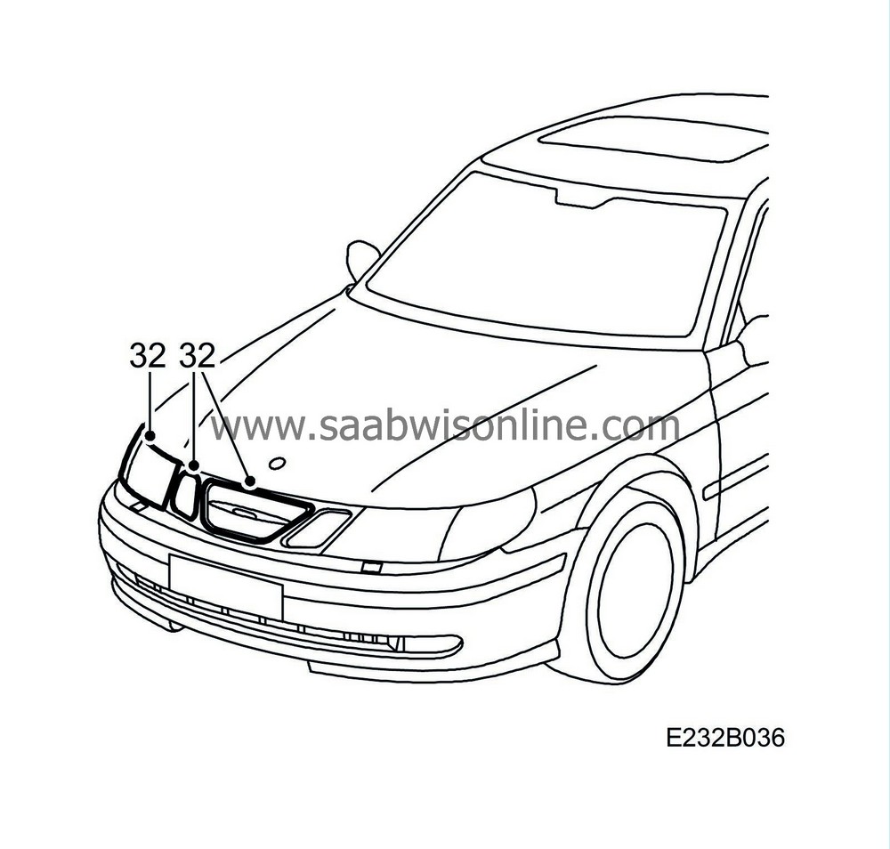
Remove the right-hand headlamp, right-hand direction indicator, centre grille and right-hand side grille. See WIS 9-5 M02 - 3. Electrical System - Lighting and signalling systems - Adjustment/Replacement - Headlamps.
|
|
3.
|
Remove the rain protection from the air intake pipe in front of the radiator and detach the air intake pipe.

|
|
4.
|
Remove the mass air flow sensor together with the upper rubber hose.

|
|
6.
|
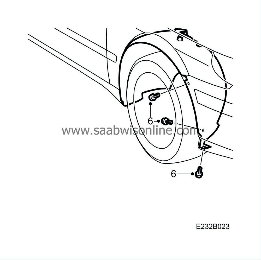
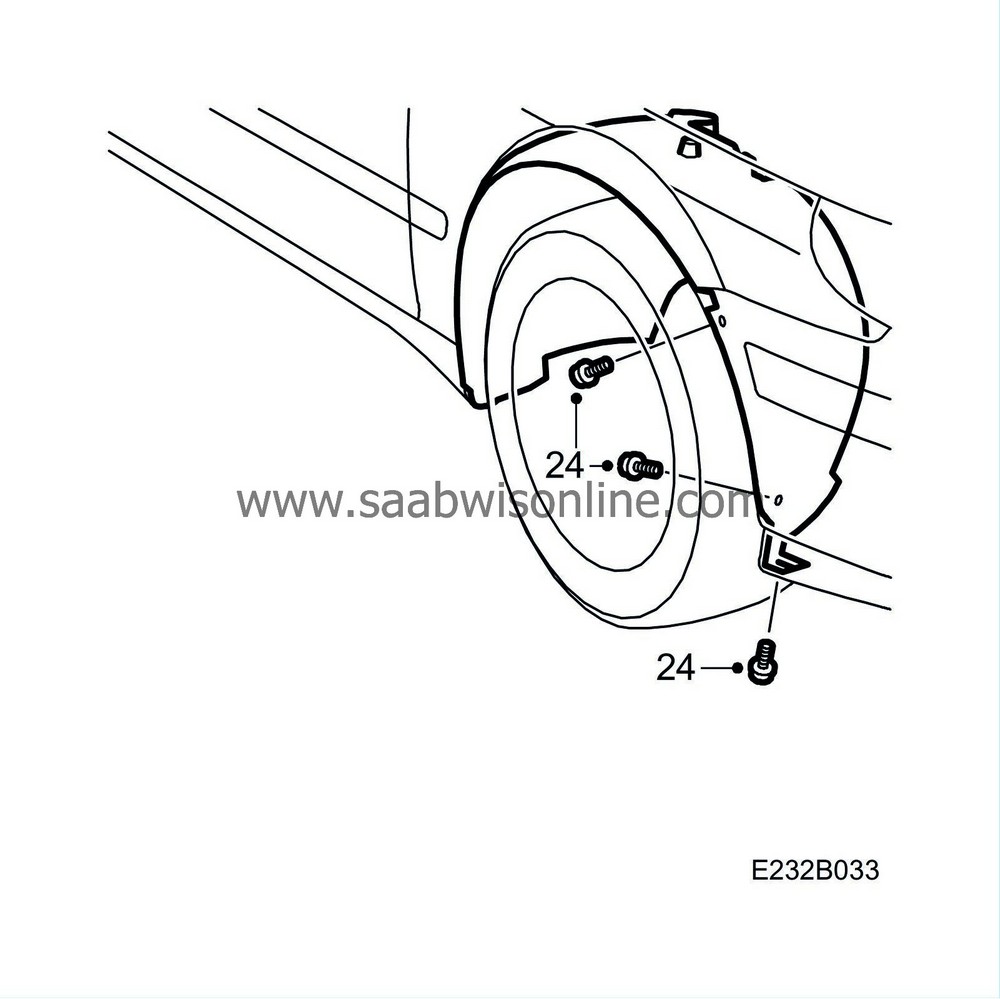
Unscrew the screws at the right-hand front edge of the wing liner.
|
|
7.
|
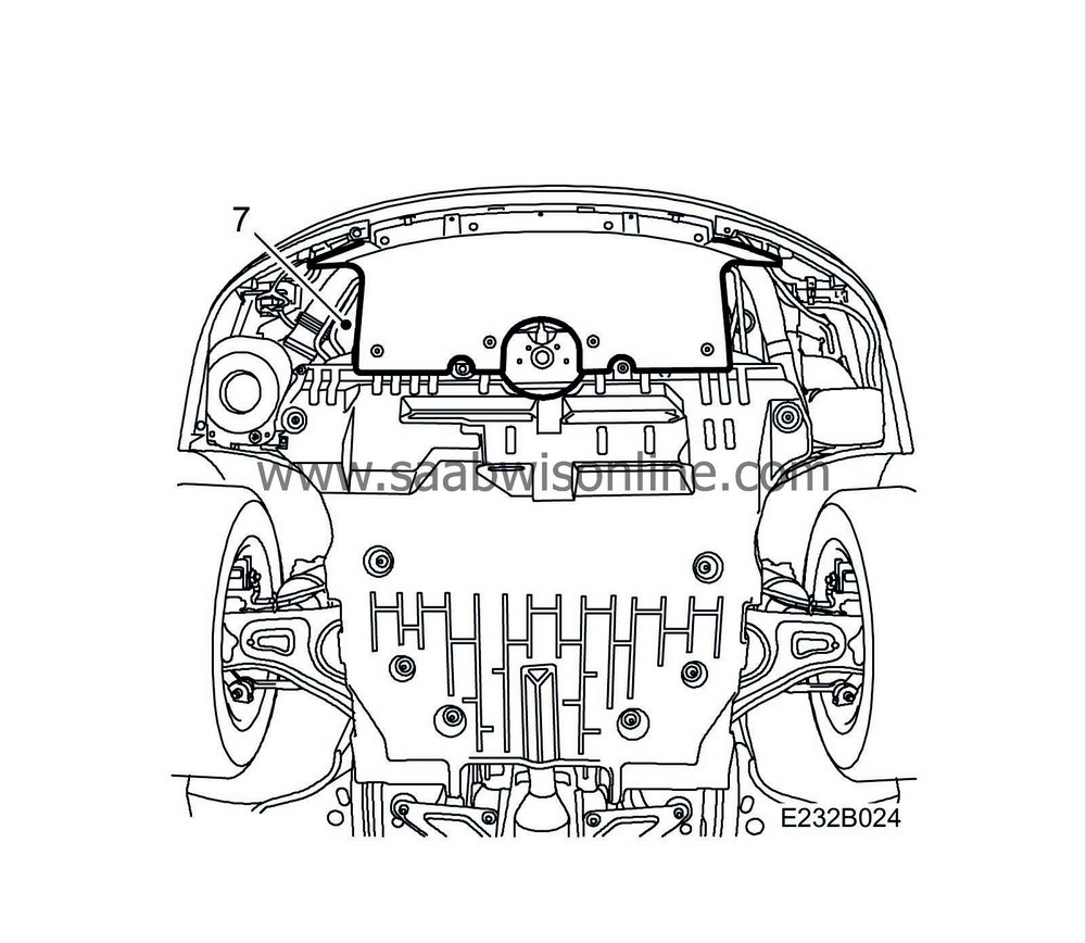
Remove the lower section of the spoiler.
|
|
8.
|
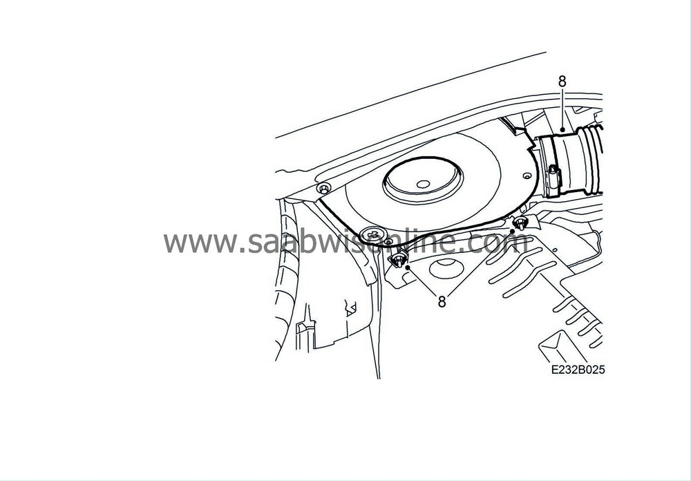
Remove the air intake pipe and air filter housing.
|
|
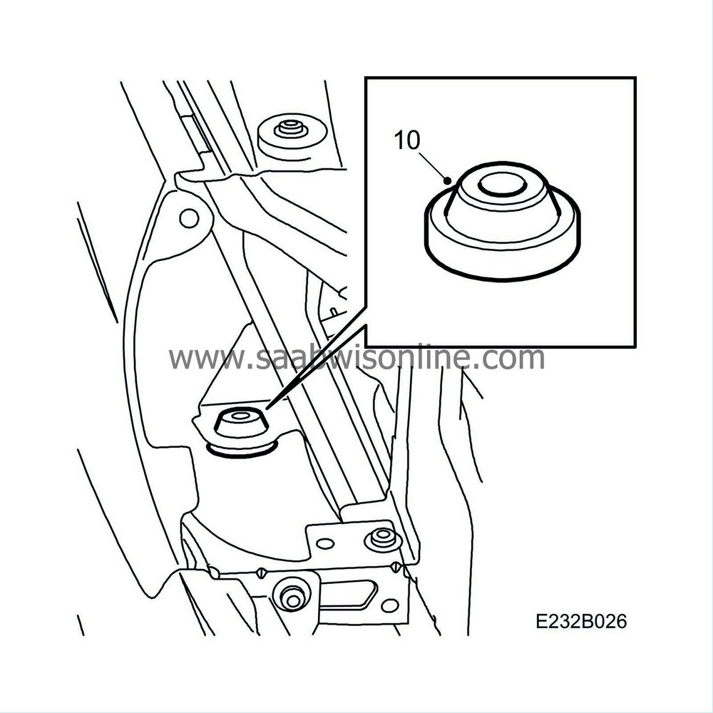
10.
|
Remove the rubber bushing from the air filter housing upper mounting bracket.
|
|
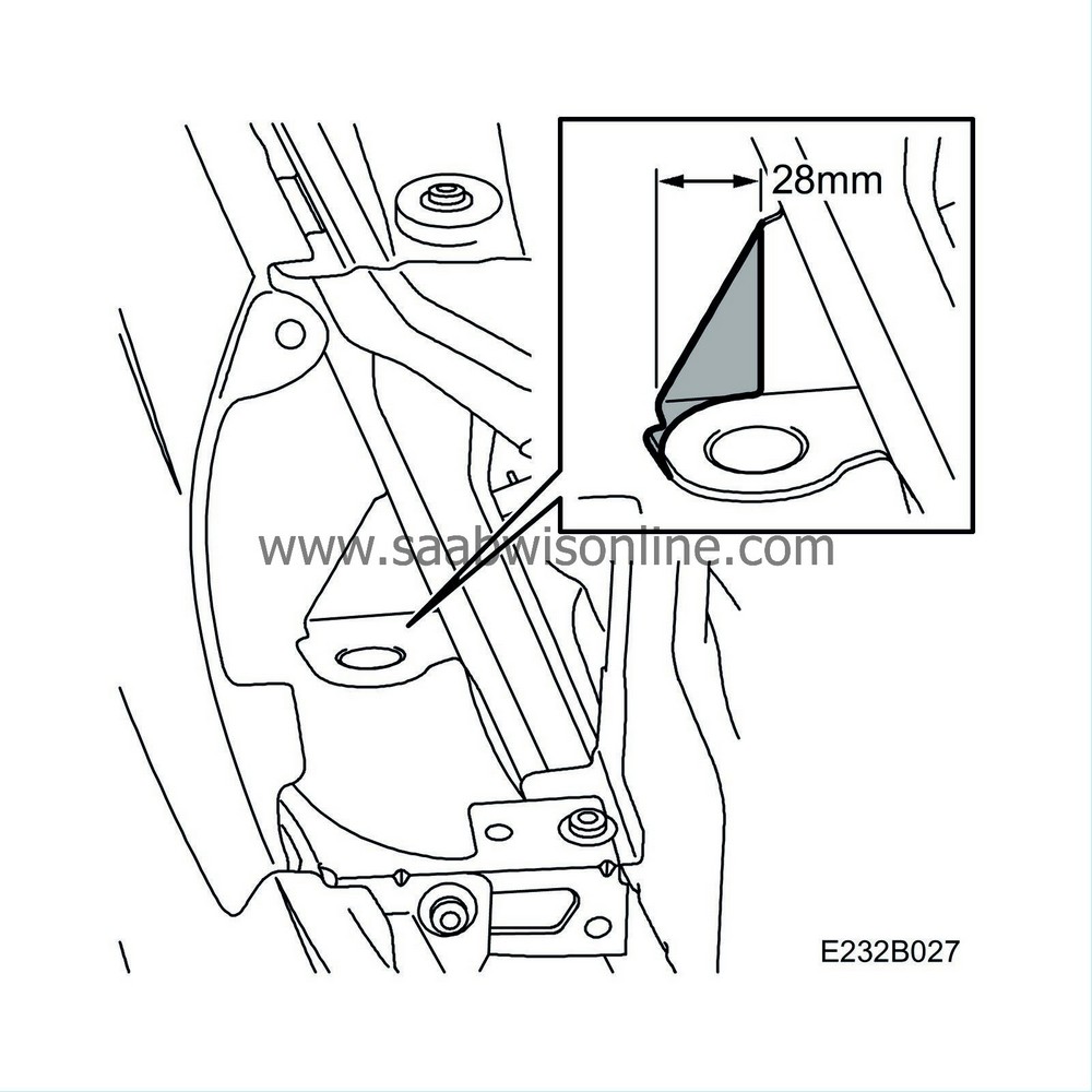
11.
|
Saw off the air filter housing upper mounting bracket as indicated in the illustration.
|
|
12.
|
Apply anti-corrosive using 1K Primer Filler (or similar).
|
|
13.
|
Detach the front section of the low pressure pipe from the compressor.
Plug the compressor opening.

|
|
14.
|
Detach the low pressure pipe from the connecting block on the right-hand structural member.
Plug the rear pipe's opening.
|
|
15.
|
Lift away the low pressure pipe.
|
|
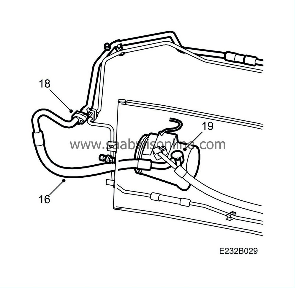
16.
|
Fit the new low pressure pipe.
|
|
17.
|
Remove the plugs from the new low pressure pipe and lubricate the O rings with synthetic vaseline.
Remove the plugs from the rear pipe and the compressor.
|
Note
|
|
Check that the low pressure pipe is fitted correctly.
|
|
|
18.
|
Press the connecting block together and screw it together.
Tightening torque 8 Nm (6 lbf ft)
|
|
19.
|
Press down the new low pressure pipe on the compressor and screw it on.
Tightening torque 20 Nm (15 lbf ft)
|
|
20.
|
Fit the chafing guard.

|
|
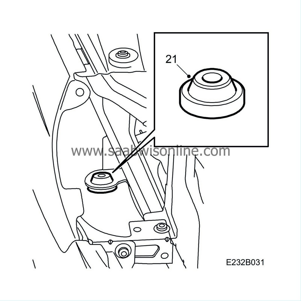
21.
|
Fit the rubber bushing on the air filter housing upper mounting bracket.
|
|
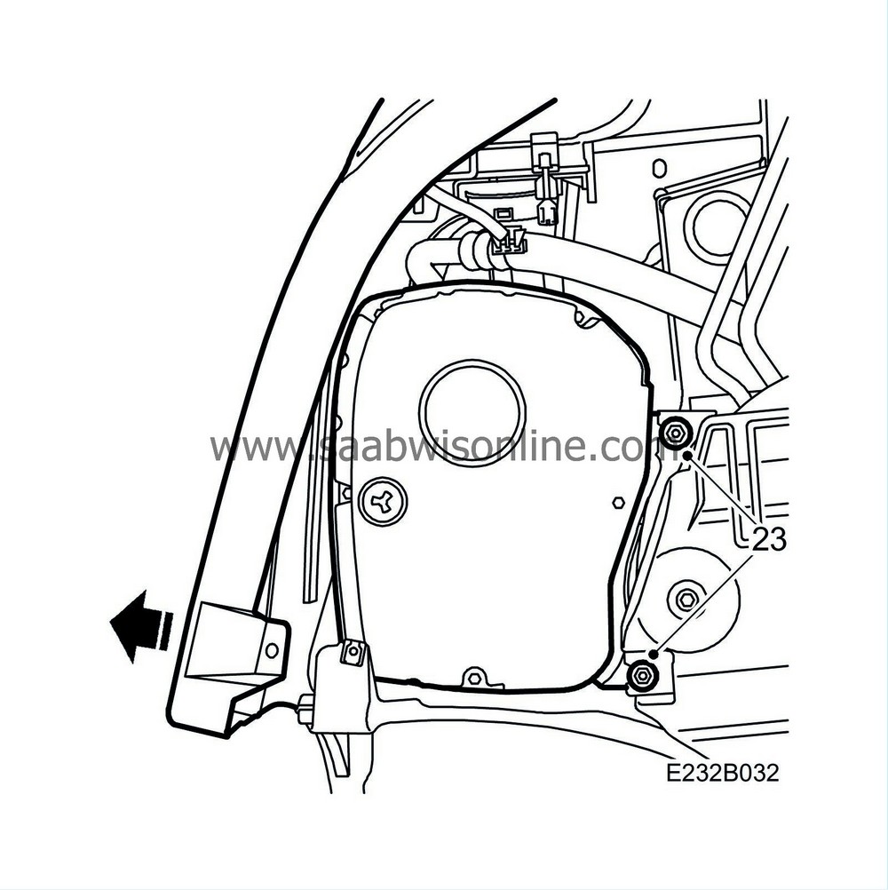
23.
|
Fit the new air filter housing.
|
|
24.
|
Fit the screws into the front edge of the wing liner.
|
|
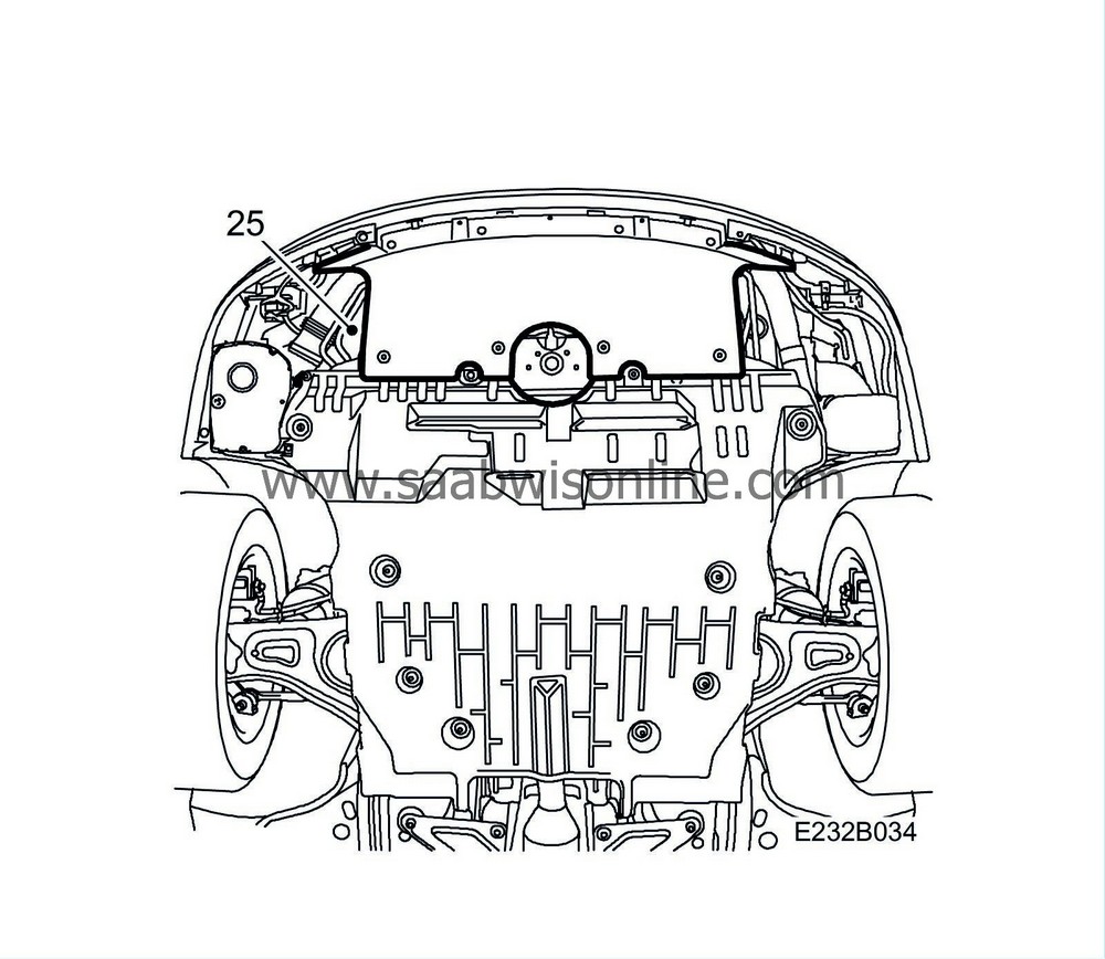
25.
|
Fit the lower section of the spoiler.
|
|
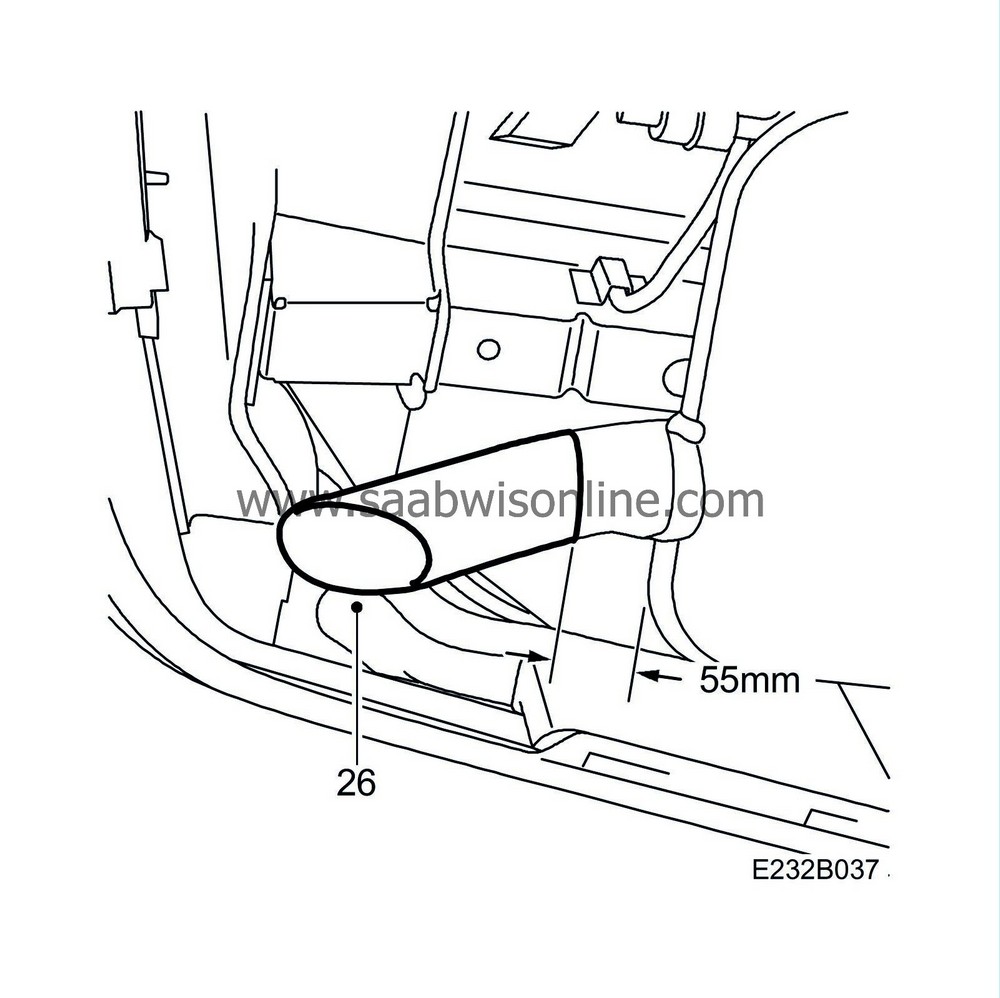
26.
|
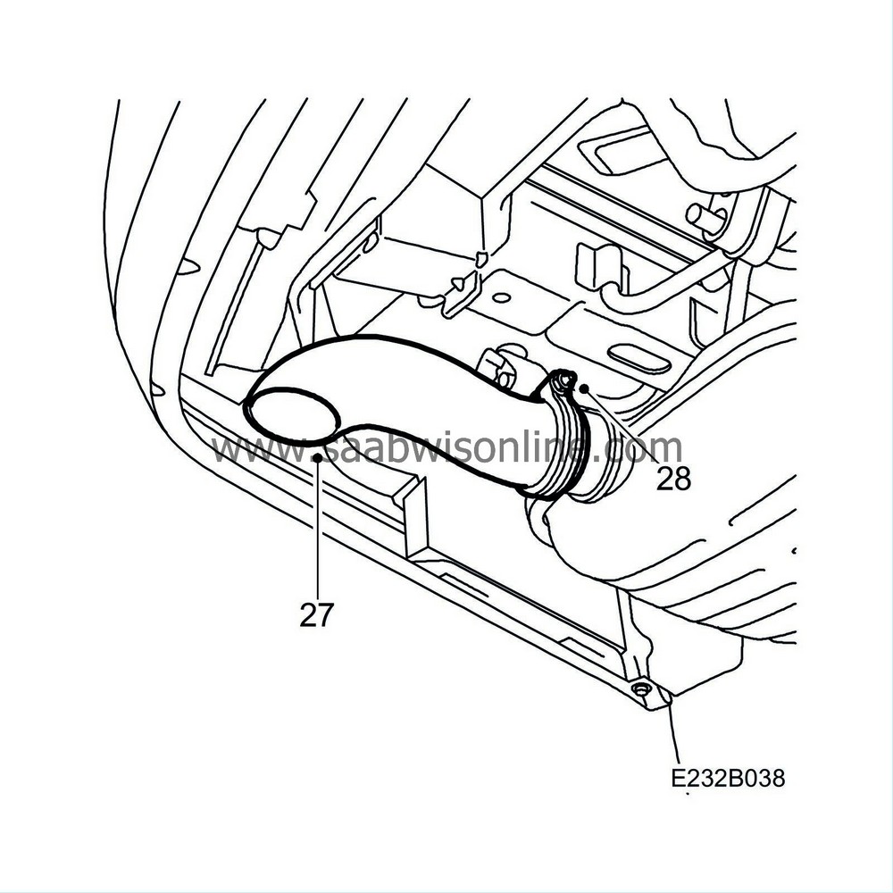
Cut the tail pipe 55 mm from the flange on the silencer. Use pipe cutter (part no. 83 95 667).
|
|
27.
|
Fit the new tail pipe together with the clamp, press the pipe in as far as possible.
|
|
28.
|
Turn the clamp to the correct position and tighten the nut.
|
|
30.
|
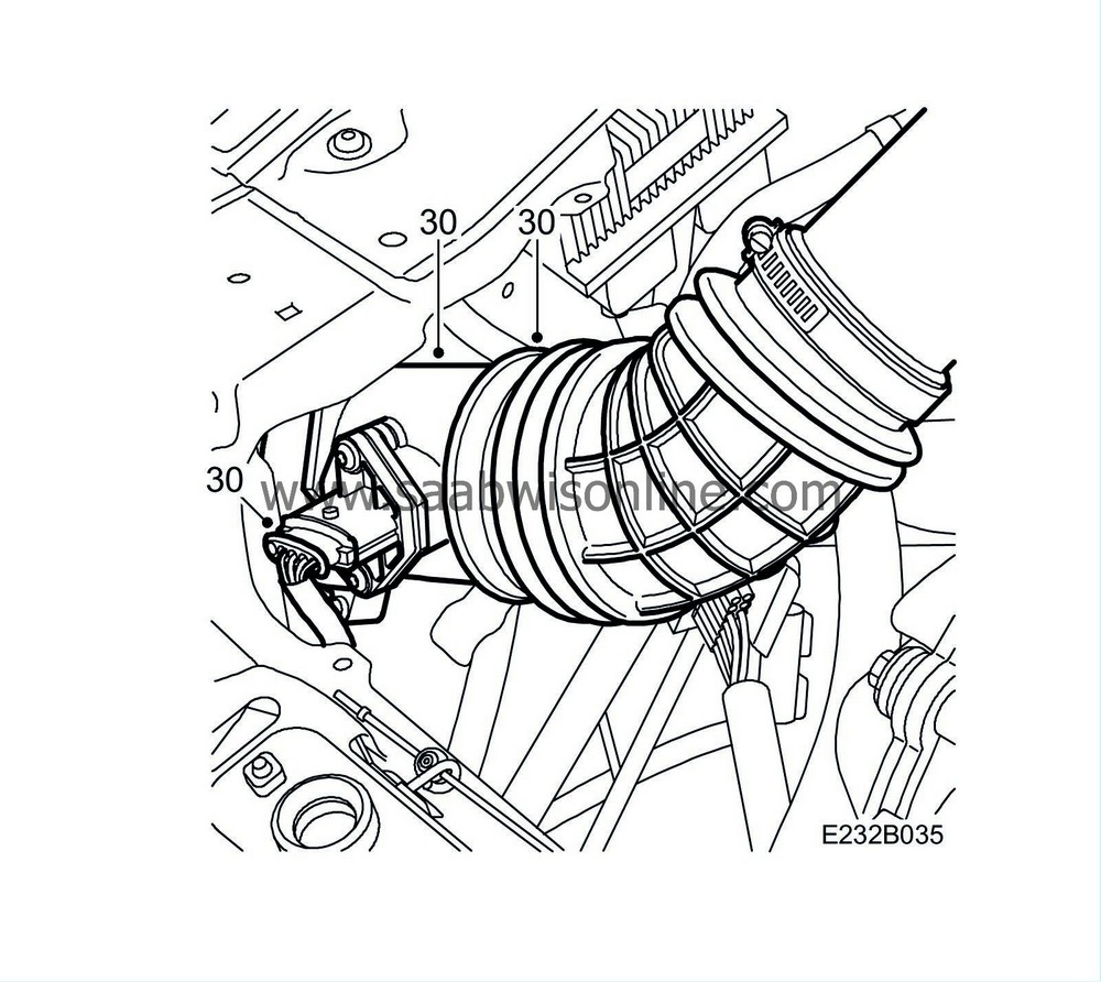
Remove the dust cap from the new air filter housing and fit the mass air flow sensor with the upper rubber hose to the air filter housing and the engine's intake manifold.
|
|
31.
|
Fill the A/C system, see WIS 9-5 M02 - 8. Body - Heating and Ventilation, A/C - Adjustment/Replacement - Draining and filling of refrigerant.
|
|
32.
|
Fit the right-hand headlamp, right-hand direction indicator, centre grille and right-hand side grille. See WIS 9-5 M02 - 3. Electrical System - Lighting and signalling systems - Adjustment/Replacement - Headlamps.
|
|
33.
|
Before starting the engine:
Reprogram the engine control module (ECM) with software: CS3MIKN8, use TIS2000 edition 2003-3, update 3 (or later) and Tech2 version 108.000.
|
Note
|
|
The engine control module must be reprogrammed when fitting the air filter housing with water separator.
|
|
When programming, select option
with water separator
when the question arises in TIS2000.
|
|
|
Marking the modification identity plate
|
On completion of the necessary procedures, mark modification identity plate box D4. If the work was carried out by the importer, mark the box with a "7". If done by a dealer, mark it with an "8".
|
Standard times-/Warranty information
|
See separate information.


