Mass air flow sensor
| Mass air flow sensor |
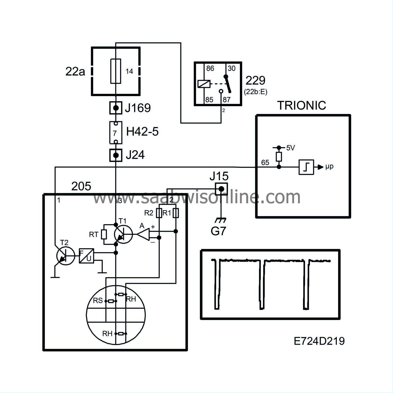
The air temperature is measured by means of a special PTC resistor (RS).
As the air flow increases, a higher voltage is required to maintain a constant temperature difference. The voltage required is converted into ground pulses, the frequency of which increases with the mass air flow.
The mass air flow sensor is grounded at grounding point G7 and supplied with current from the main relay. Note that input pin 65 of the control module has a pull-up to 5 V and that the mass air flow sensor pulses to ground.
When the ignition switch is turned “ON”, the main relay operates and B+ is applied to pin 3 of the mass air flow sensor. A current passes RT and the low-ohmic thermal resistors RH via R1 to ground. Since the RH resistors are cold, their resistance is low. The amplifier then sends a strong base current to transistor T1, whereupon RH quickly heat up. As RH heat up, their resistance increases and a state of equilibrium is achieved.
If RH is cooled by an airstream, its temperature will immediately be restored by an increase in current through transistor T1. The voltage required to maintain a constant resistance in RH is supplied to a frequency converter, which in turn controls transistor T2. T2 grounds the control module input with a frequency corresponding to the air mass flow. The ground pulses have a duration of 40 µs.
The temperature sensor resistor RS is included in a circuit together with R2, the objective of which is to correct amplifier A so that the temperature of RH is always 220°C above the air temperature.
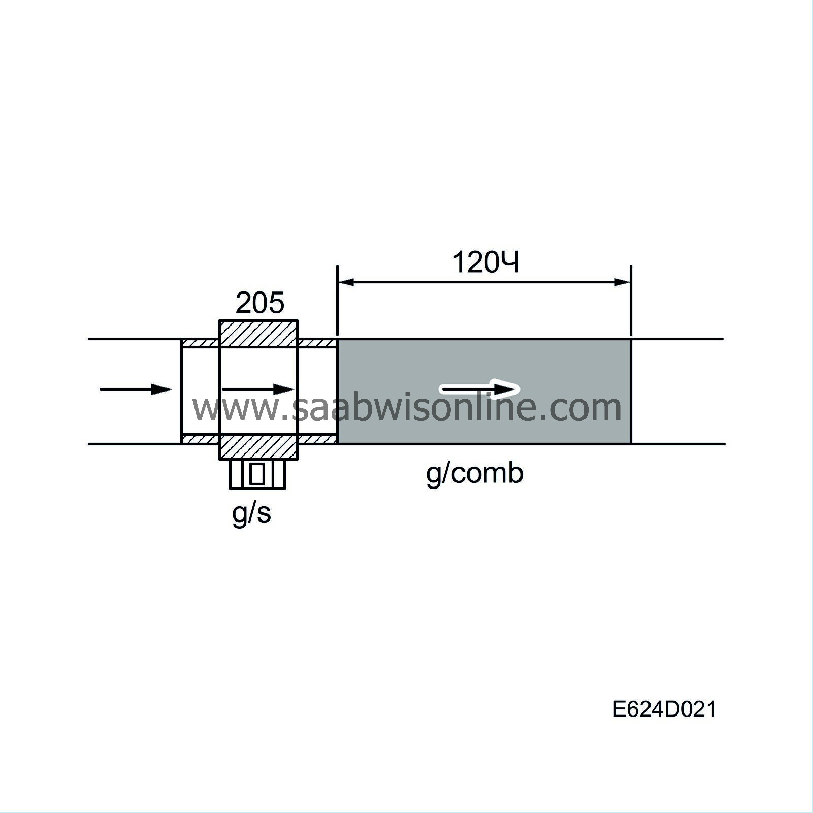
The control module coverts the frequency to grams per second and then, assisted by the value from the crankshaft position sensor, to milligrams air per combustion. The unit is written mg/c (milligrams per combustion) and constitutes the principal value for the fuel injection. Normally, 1 mg fuel is consumed at 14.7 mg/c. The value is also a good indication of the engine torque or load.

| Diagnostics |
If the mass air flow sensor develops a fault, three different diagnostic trouble codes may be generated:
| • |
If the mass air flow sensor does not send any frequency at all to the control module, diagnostic trouble code P0100 will be generated. The cause may be a break in one of the leads.
|
|
| • |
If the frequency is too low, trouble code P0102 will be generated. The cause may be a major leak between the mass air flow sensor and the throttle body or an internal fault in the mass air flow sensor.
|
|
| • |
If the frequency is too high, trouble code P0103 will be generated. The cause is an internal fault in the mass air flow sensor.
|
|
| System reaction to a fault |
| • |
As soon as the control module has detected the fault, the intake pressure and intake air temperature are used as substitute values during the remainder of the driving time.
Fuel adaptation is zeroed. |
|


