(02-09-384) Navigation System with Audio
Symptom: Calculated arrival time does not match the stated route distance and car speed.
The display is black in one or more menus.
None or only a few channels remain in the memory.
One or more memory buttons not working.
The marker does not follow the route the car is driving.
Speed signal in the display does not correspond with the car's speedometer.
No image on the screen in any mode.
The system can be shutdown while driving and restarted once by pressing on/off. It will then work for a maximum of 45 minutes and with then not work.
No image on the screen.
None or poor sound from one or more loudspeakers.
None or poor sound from one or more loudspeakers when playing CD discs.
None or poor sound from one or more loudspeakers when using navigation.
None or poor sound from one or more loudspeakers when using the radio.
Steering wheel controls do not work.
Navigation assistance does not work.
No navigation functions work.
The display does not blacken when Night Panel is activated.
|
TECHNICAL NEWS
|
|
Bulletin Nbr:
|
02-09-384
|
|
Date:
...........
|
September 2002
|
|
Market:
|
Enl. sep. lista
|
|
|
Navigation System with Audio
|
9-5 M03
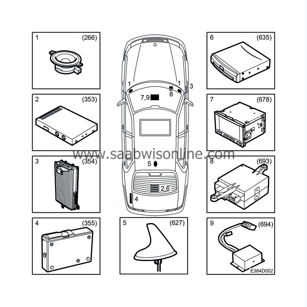
|
1.
|
Loudspeakers, dashboard (266 FR, FL)
|
|
2.
|
Main unit, Audio (353)
|
|
3.
|
Amplifier, Audio (354)
|
|
5.
|
Antenna, GPS/GSM (627)
|
|
6.
|
Main unit, Navigation (635)
|
|
7.
|
Control Panel, Navigation/Audio (678)
|
|
8.
|
Switch, Navigation/Telephone (693)
|
|
9.
|
Signal converter, I-bus (694)
|
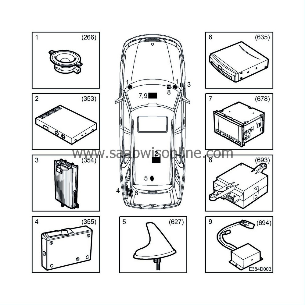
|
1.
|
Loudspeakers, dashboard (266 FR, FL)
|
|
2.
|
Main unit, Audio (353)
|
|
3.
|
Amplifier, Audio (354)
|
|
5.
|
Antenna, GPS/GSM (627)
|
|
6.
|
Main unit, Navigation (635)
|
|
7.
|
Control Panel, Navigation/Audio (678)
|
|
8.
|
Switch, Navigation/Telephone (693)
|
|
9.
|
Signal converter, I-bus (694)
|
General
The navigation system uses GPS (Global Positioning System). GPS comprises 27 satellites in an orbit around the world at a height of 20,200 km. In order to determine the location of the car there must always be at least 3 satellites accessible to the user on the ground and these determine the position of the car anywhere in the world. Within the car's different systems are direction and speed sensors and a DVD player with a digitised map, which together with GPS is used to calculate the route to the selected destination.
The 7" touch screen is used partly as a control panel and partly as the main window to generate and manage routes, to specify routes, manage stored routes, display maps, guidance and for traffic information using text.
The navigation unit contains a GPS receiver which receives the signals from the GPS antenna on the roof of the car from which the position of the car is calculated. The navigation unit contains a gyro so that the system will know the direction in which the car is headed. There is also a DVD reader in the navigation system for the digital maps.
All calculations made by the navigation unit are then sent to the radio receiver which in turn furthers all information to other units involved.
Main unit, Navigation
The main navigation system unit is the DVD/Navigation unit which is located in the car's luggage compartment. Apart from carrying out the route calculations it also includes a DVD player for the digital maps and a gyro which monitors the direction of the car.
Control Panel, Navigation/Audio
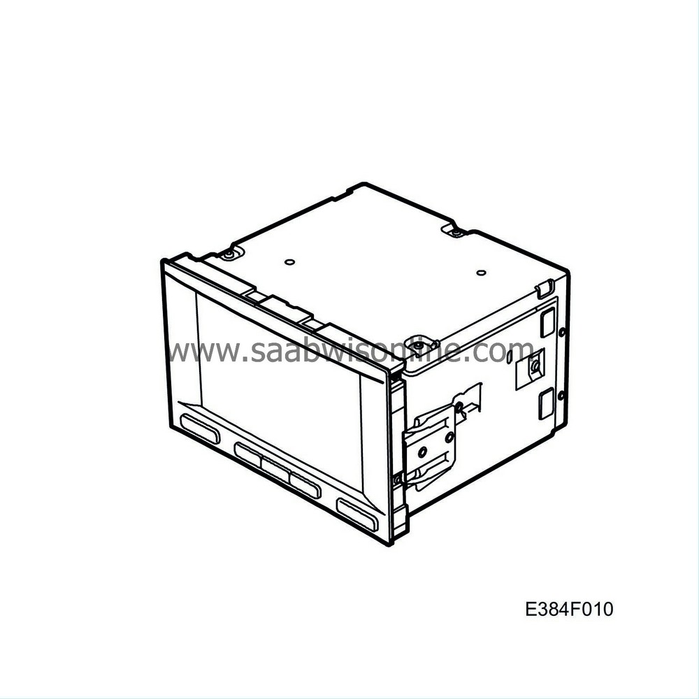
Centrally located in the centre console is the 7" colour screen. In the lower section of the touch screen frame are push-buttons to start the system and adjust the volume as well as buttons to select radio/CD or navigation and a button for different display settings. When the system is started by the On/Off button, the part of the system to be used is selected using push-buttons, following which all other choices are by means of the touch screen, such as selection of radio station or navigation destination.
Signal converter, I-bus
A signal converter is fitted underneath the control panel. This converts I-bus messages to a specially developed communication system so that the steering wheel buttons can be used to raise and lower the system volume as well as to raise the volume in the event of increased speed.
Main unit, Audio
The radio receiver located in the car's luggage compartment receives information from the navigation unit. The radio receiver in turn transmits the information received on to the colour screen.
Amplifier, Audio
In order to be able to hear the navigation system voice guidance the external amplifier from the Premium and Prestige audio systems is used.
Loudspeakers, dashboard
The outer dashboard loudspeakers are used or navigation system voice guidance.
Switch, Navigation/Telephone
A switch is fitted in front of the glove box which senses the key position and controls when the components can be started or shut down.
It handles the mobile phone's hands free signal which subdues the radio/navigation volume in the event of incoming calls. In addition allows the raising or lowering of the telephone volume using the steering wheel buttons.
Antenna, GPS
The GPS/GSM roof antenna is fitted into the car roof. The antenna is connected to the navigation system unit which houses the GPS receiver.
Communication
The communication between the different units takes place using a specially developed bus communication system.
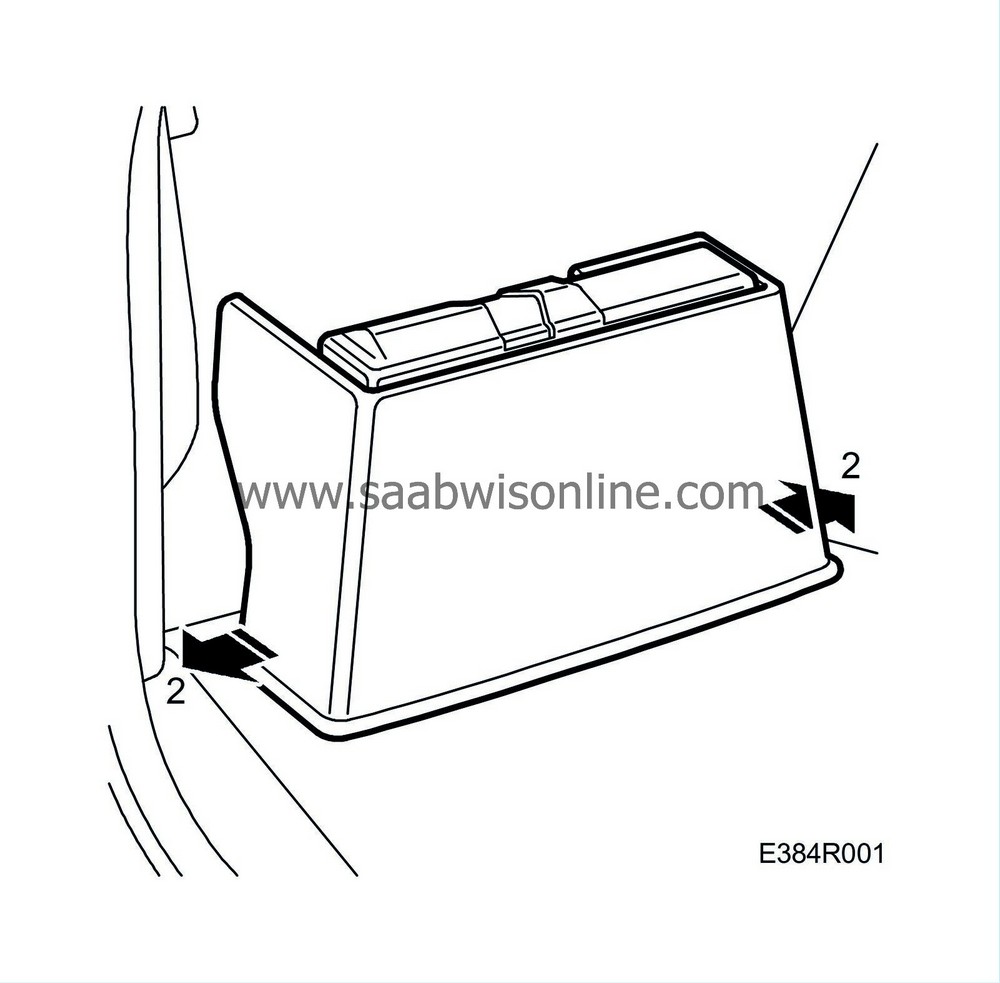
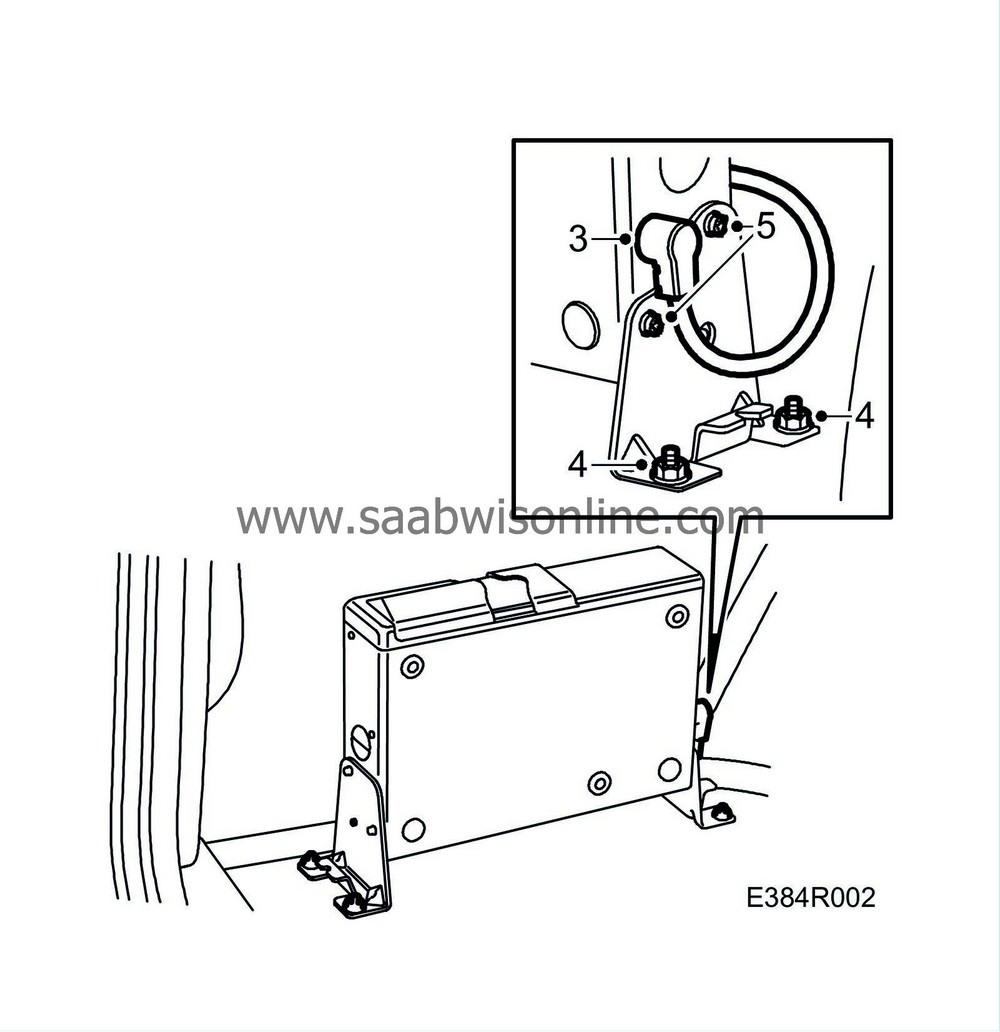
CD changer (4D)
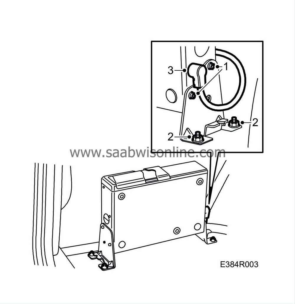
To remove
|
2.
|
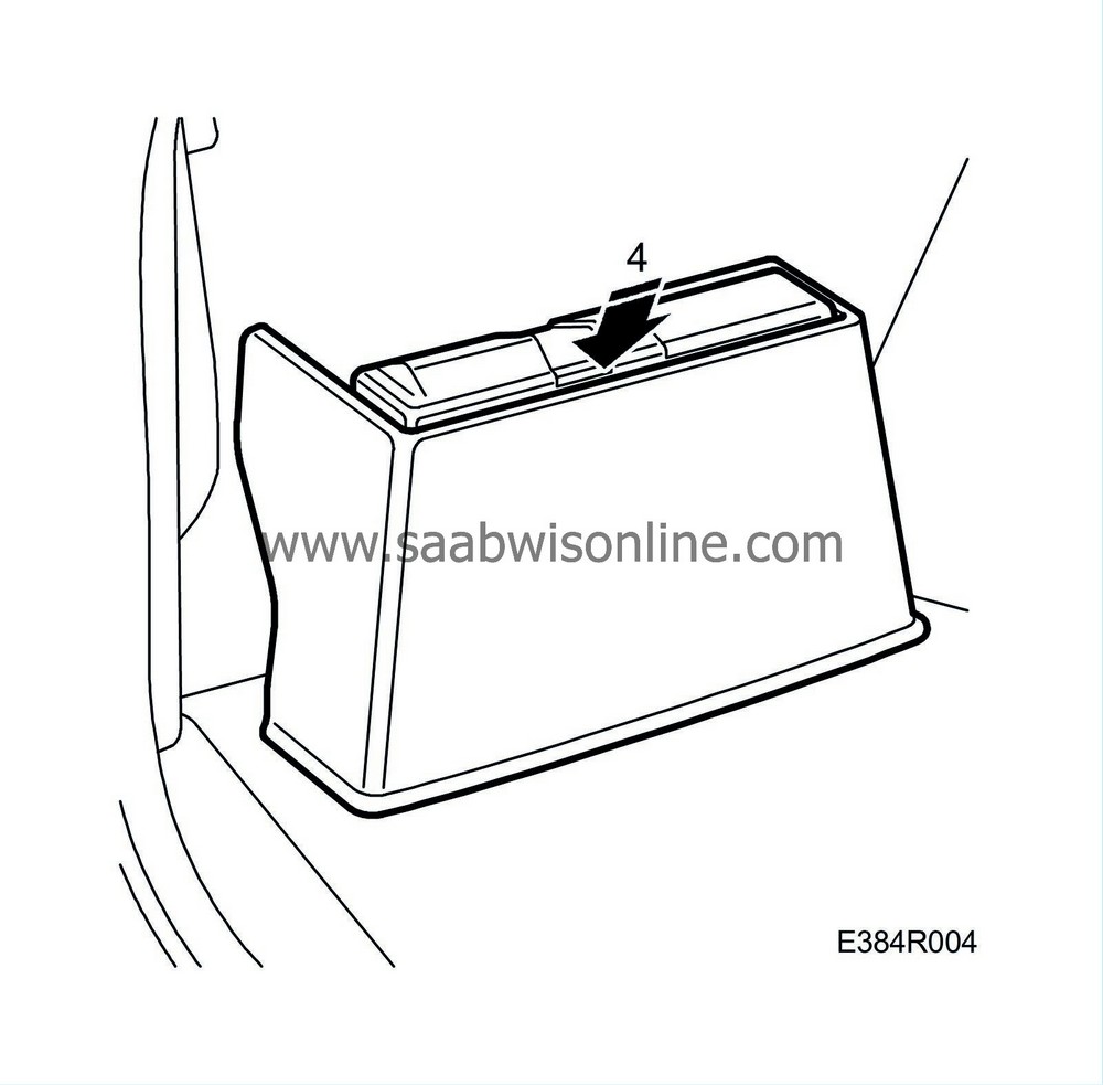
Remove the casing by pulling the edges outwards.
|
|
3.
|
Remove the connector.
|
|
4.
|
Remove the bracket nuts from the floor.
|
|
5.
|
Remove the CD changer from the brackets.
|
To fit
|
1.
|
Fit the brackets to the CD changer.
|
|
2.
|
Fit the bracket nuts to the floor.
|
|
3.
|
Plug in the connector.
|
|
4.
|
Fit the casing by pressing it downwards.
|
CD changer (5D)
To remove
|
2.
|
Remove the luggage compartment trim. See WIS: 8. Body - Interior equipment - Adjustment/Replacement - Luggage compartment trim, side trim, 5D.
|
|
3.
|
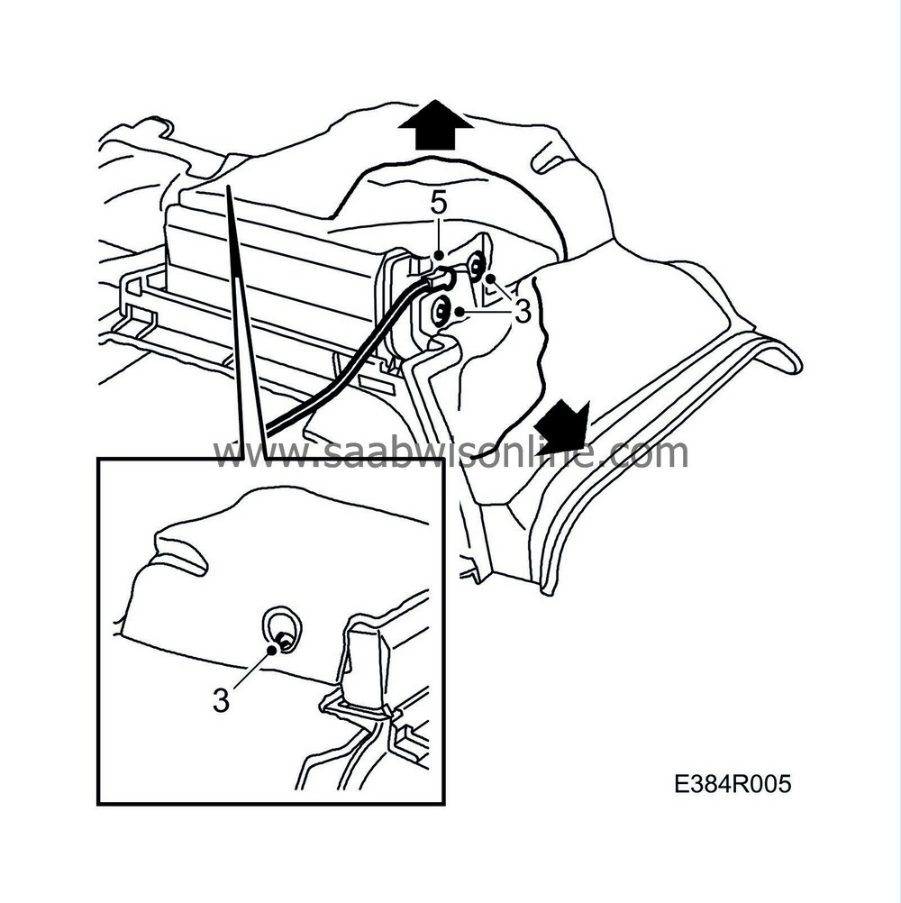
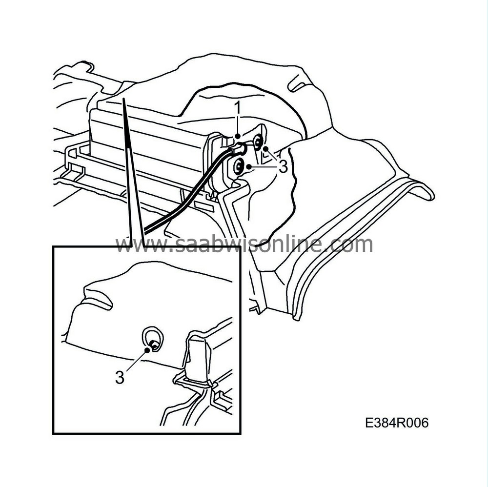
Remove the screws.
|
|
5.
|
Remove the CD player connector.
|
To fit
|
1.
|
Connect the CD player connector.
|
|
4.
|
Fit the luggage compartment trim. See WIS: 8. Body - Interior equipment - Adjustment/Replacement - Luggage compartment trim, side trim, 5D.
|
Main unit, Audio (4D)
To remove
|
2.
|
Remove the bracket.
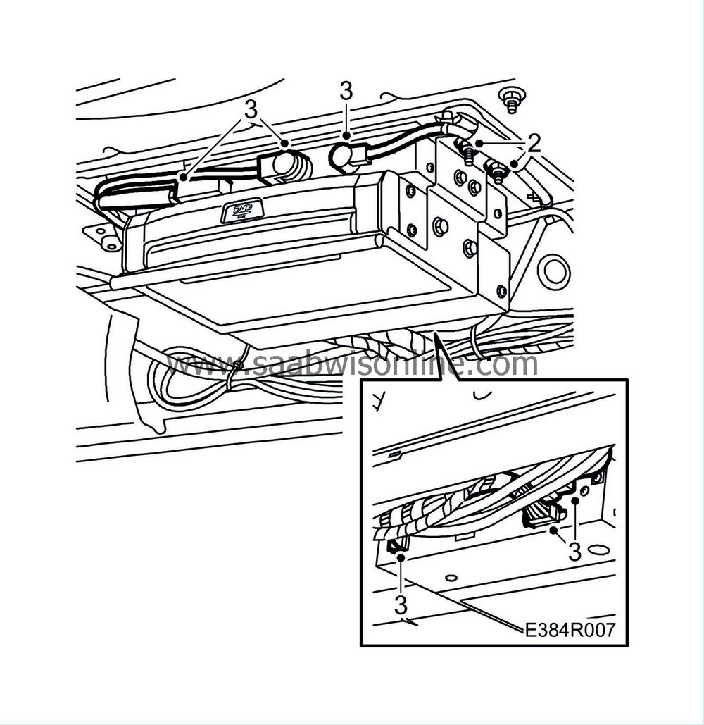
|
|
4.
|
Remove the main unit from the bracket.
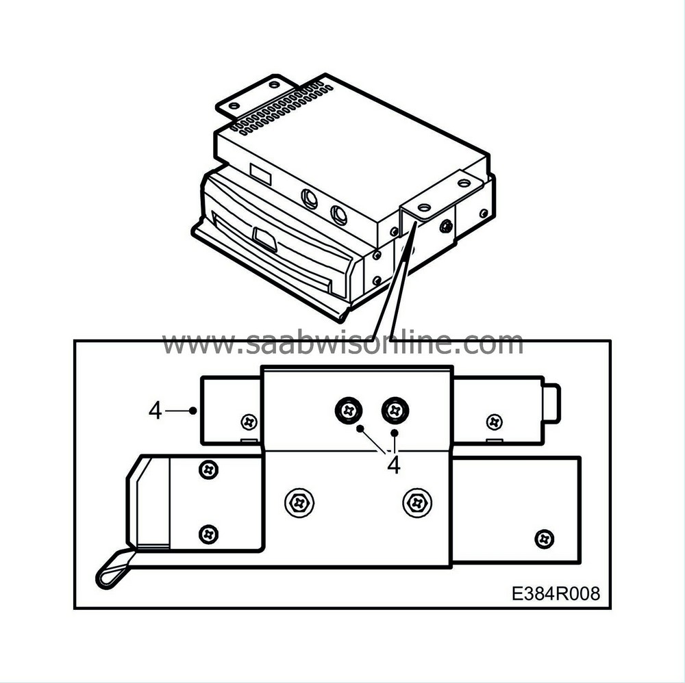
|
To fit
|
1.
|
Fit the main unit in the bracket.
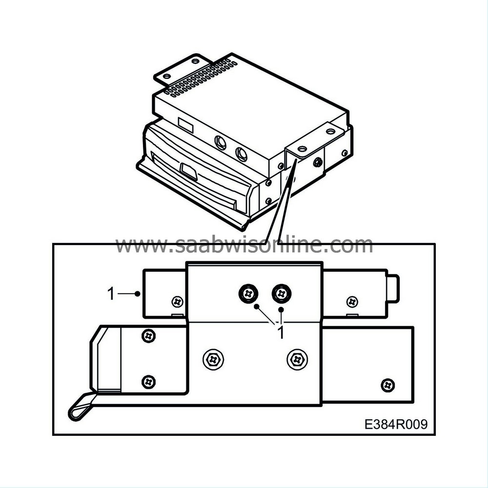
|
|
2.
|
Connect the connector.
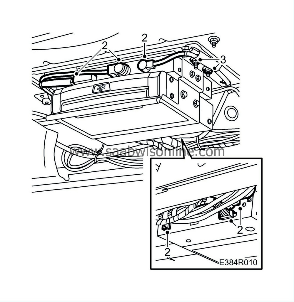
|
Main unit, Audio (5D)
To remove
|
1.
|
Open the tailgate and the rear doors.
|
|
2.
|
Lower the rear seat back supports.
|
|
3.
|
Remove the luggage compartment floor, front edge clips and rear edge handles.
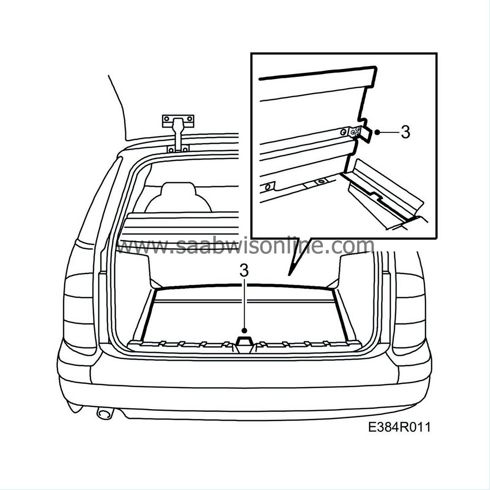
|
|
4.
|
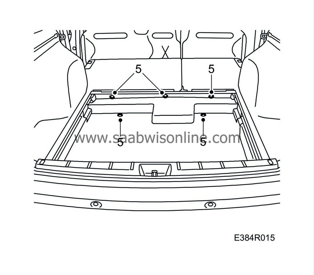
Remove the trim covering the spare wheel, 3 clips and 2 nuts in front edge.
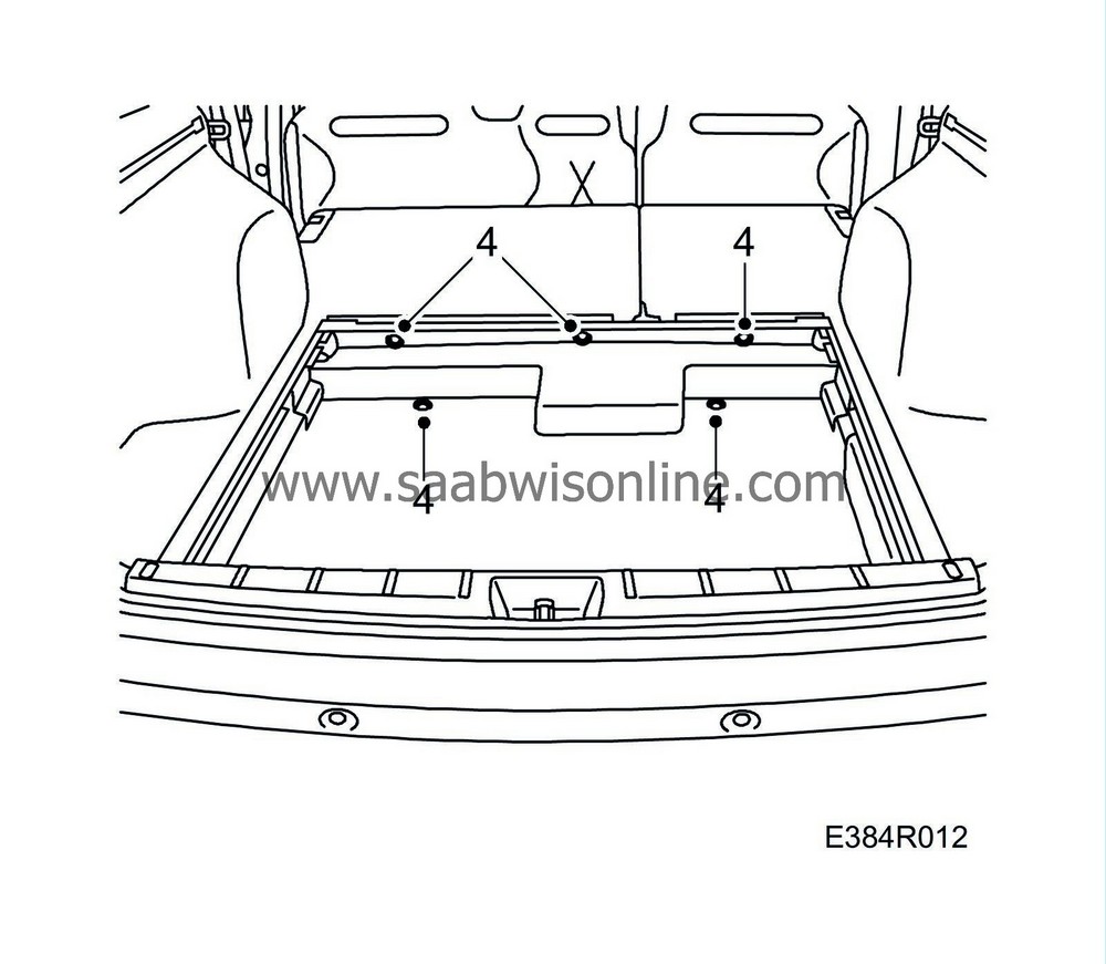
|
|
5.
|
Remove the main unit rear connector.
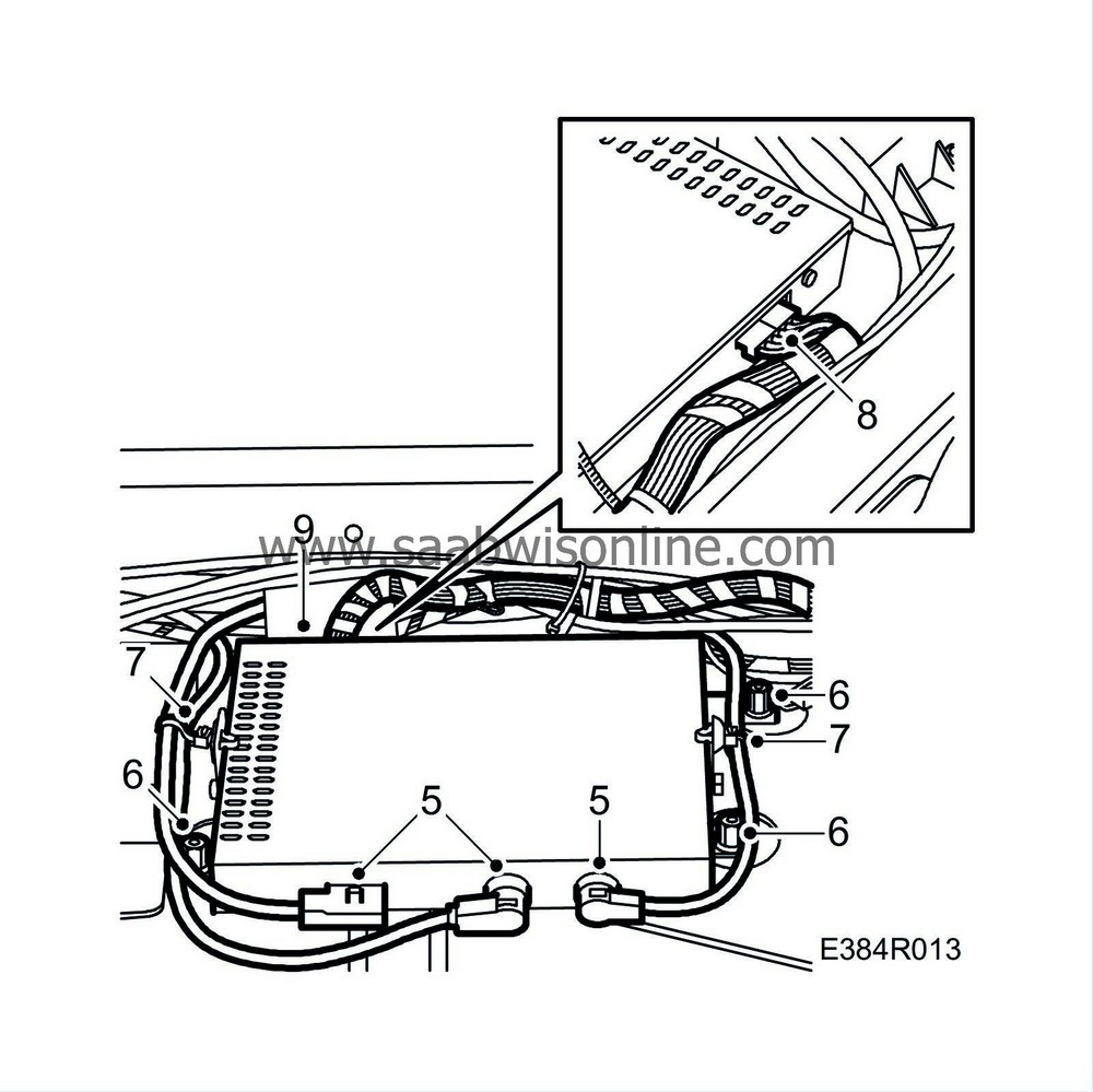
|
|
7.
|
Remove the clips from the leads.
|
|
8.
|
Remove the main unit front connector.
|
|
9.
|
Remove the main unit from the brackets.
|
To fit
|
1.
|
Fit the main unit in the brackets.
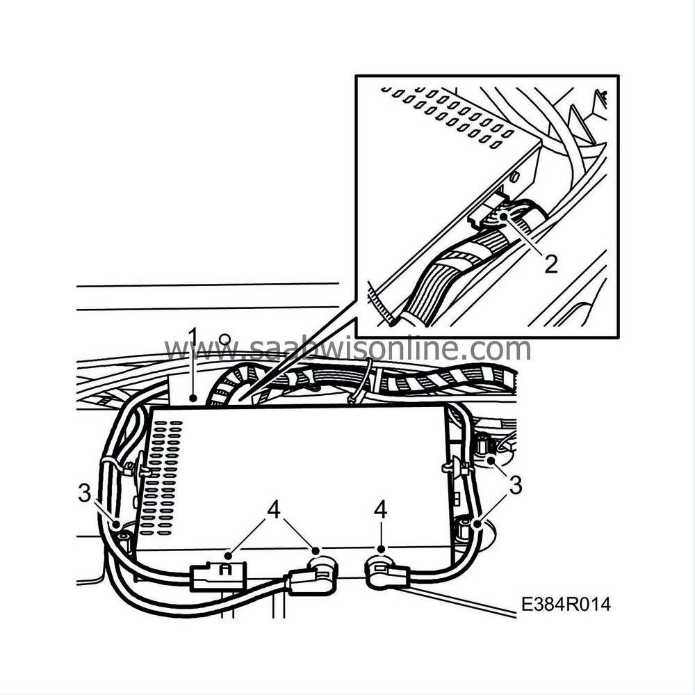
|
|
2.
|
Connect the main unit front connector.
|
|
4.
|
Connect the main unit rear connector.
|
|
5.
|
Fit the trim covering the spare wheel, 3 clips and 2 nuts in front edge.
|
|
6.
|
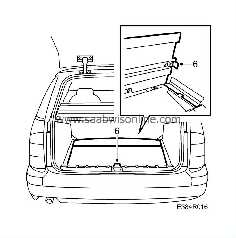
Fit the luggage compartment floor.
|
|
7.
|
Raise the back supports.
|
|
8.
|
Close the tailgate and the rear doors.
|
Main unit, Navigation (4D)
To remove
|
Note
|
|
Save all data on the Flash card before the main unit is replaced.
|
|
2.
|
Lower the rear seat back supports.
|
|
3.
|
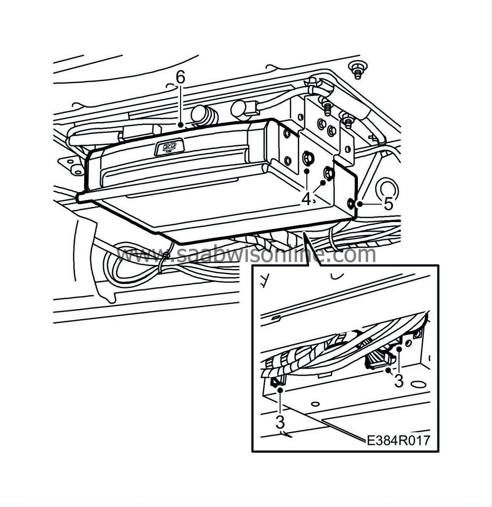
Remove the connector.
|
|
4.
|
Remove the screws in the bracket.
|
|
5.
|
Remove the rear side screws in the main unit.
|
To fit
|
1.
|
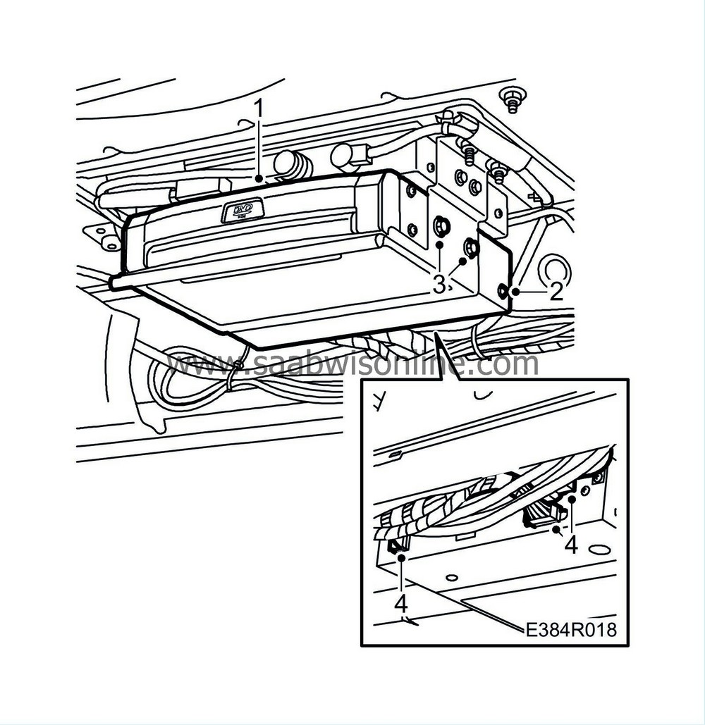
Fit the main unit.
|
|
2.
|
Fit the rear side screws in the main unit.
|
|
3.
|
Fit the screws in the console.
|
|
4.
|
Connect the connector.
|
|
5.
|
Raise the back supports.
|
Main unit, Navigation (5D)
To remove
|
Note
|
|
Save all data on the Flash card before the main unit is replaced.
|
|
2.
|
Remove the luggage compartment side trim. See WIS: 8. Body - Interior equipment - Adjustment/Replacement - Luggage compartment trim, side trim, 5D.
|
|
3.
|
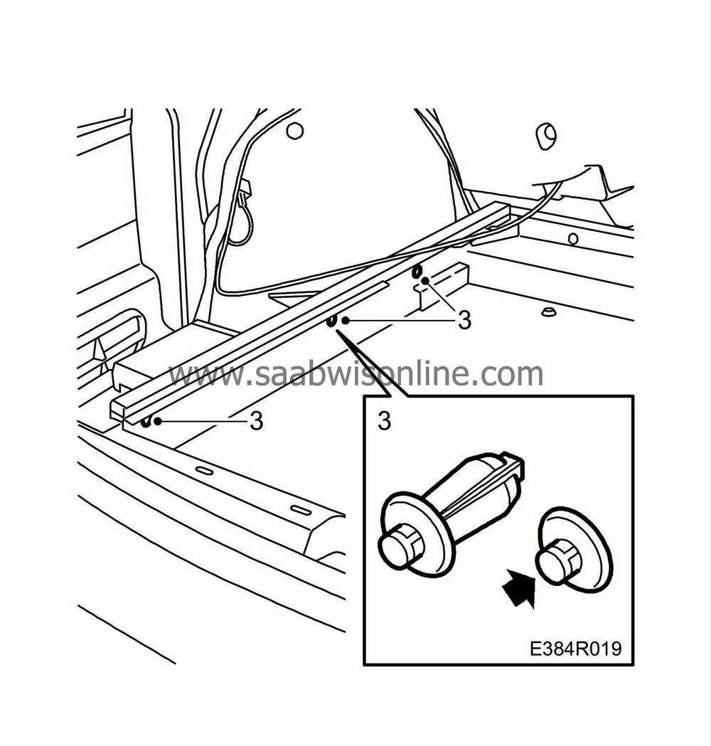
Remove the side trim clips.
|
|
4.
|
Draw the side trim away.
|
|
5.
|
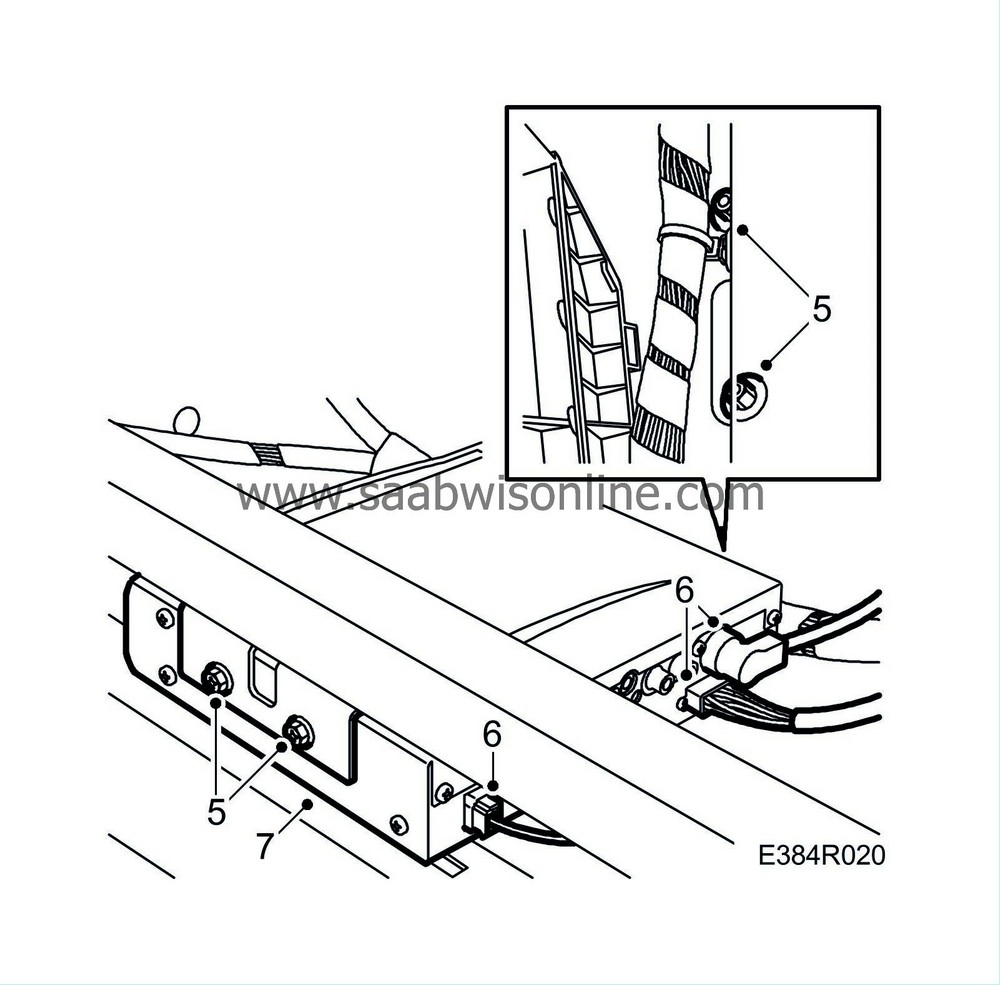
Remove the screws and nuts.
|
|
8.
|
Remove the left-hand bracket.
|
To fit
|
1.
|
Fit the left-hand bracket.
|
|
2.
|
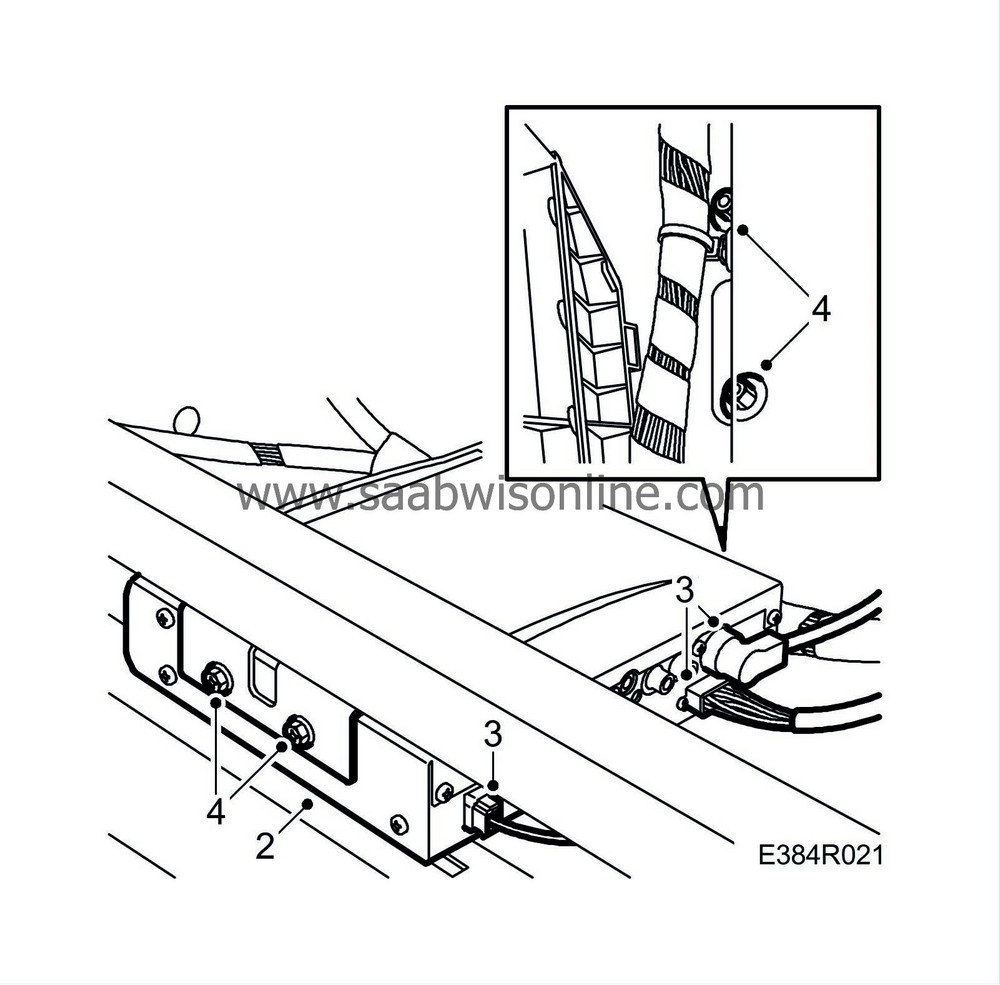
Fit the main unit.
|
|
3.
|
Connect the connector.
|
|
4.
|
Fit the screws and nuts.
|
|
5.
|
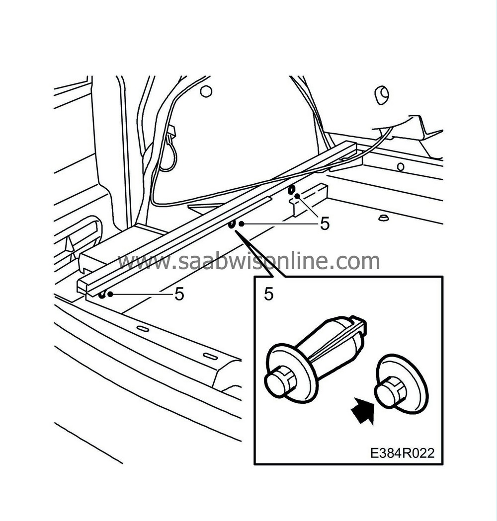
Fit the side trim clips.
|
|
6.
|
Fit the luggage compartment side trim. See WIS: 8. Body - Interior equipment - Adjustment/Replacement - Luggage compartment trim, side trim, 5D.
|
Control panel, Nav/Audio
To remove
|
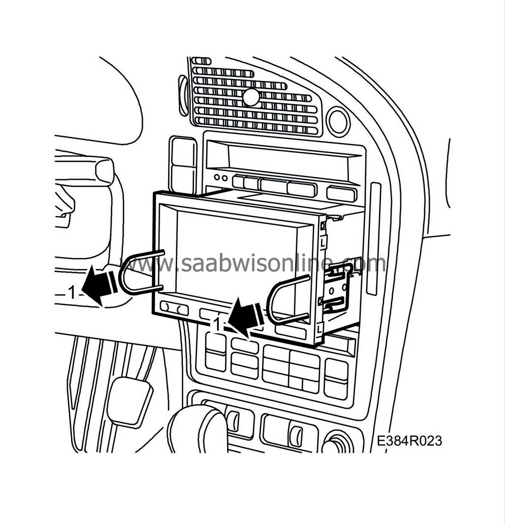
1.
|
Remove the main unit using 84 71 161 Removal tool, audio system. See WIS: 3. Electrical System - Audio System - Special Tools.
|
|
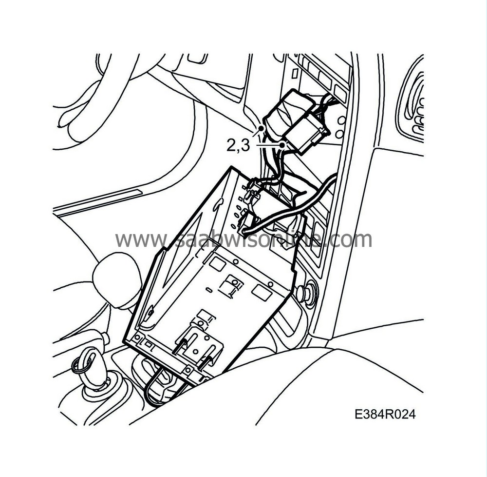
2.
|
Remove the connector insulation.
|
To fit
|
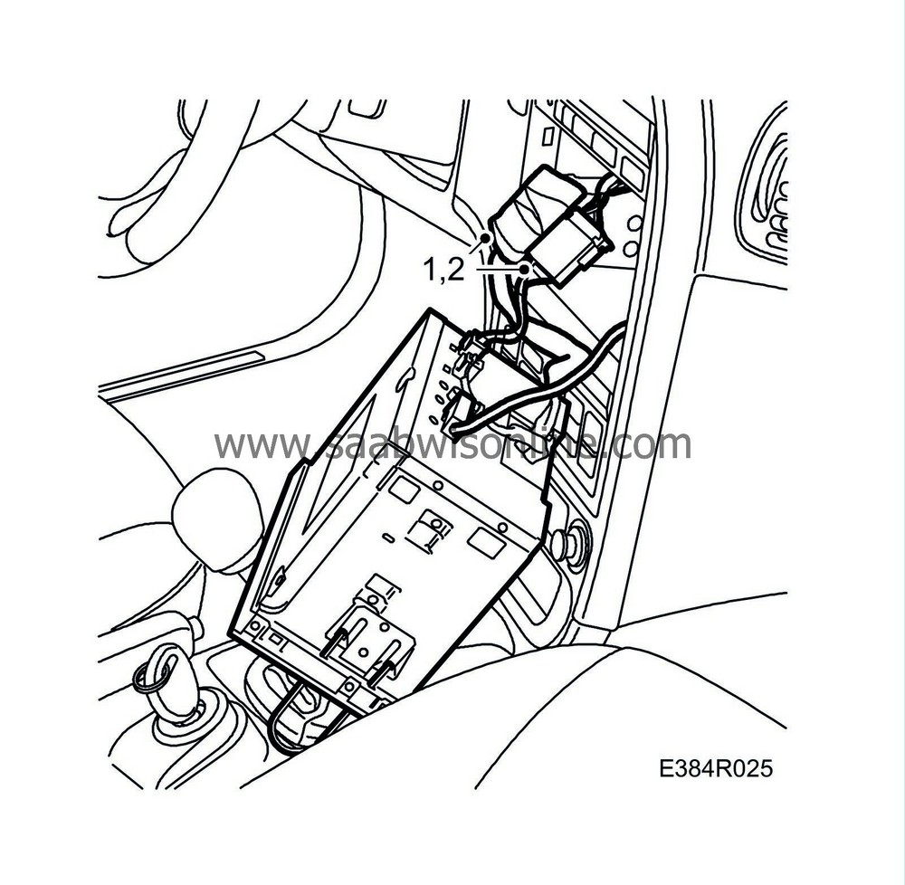
1.
|
Connect the connector.
|
|
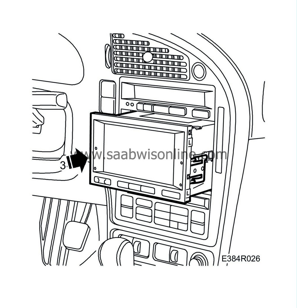
3.
|
Fit the main unit by pressing it in.
|
Switch, Nav/Tele
To remove
|
1.
|
Remove the glove box. See WIS: 8. Body - Interior equipment - Adjustment/Replacement - Glove box.
|
|
2.
|
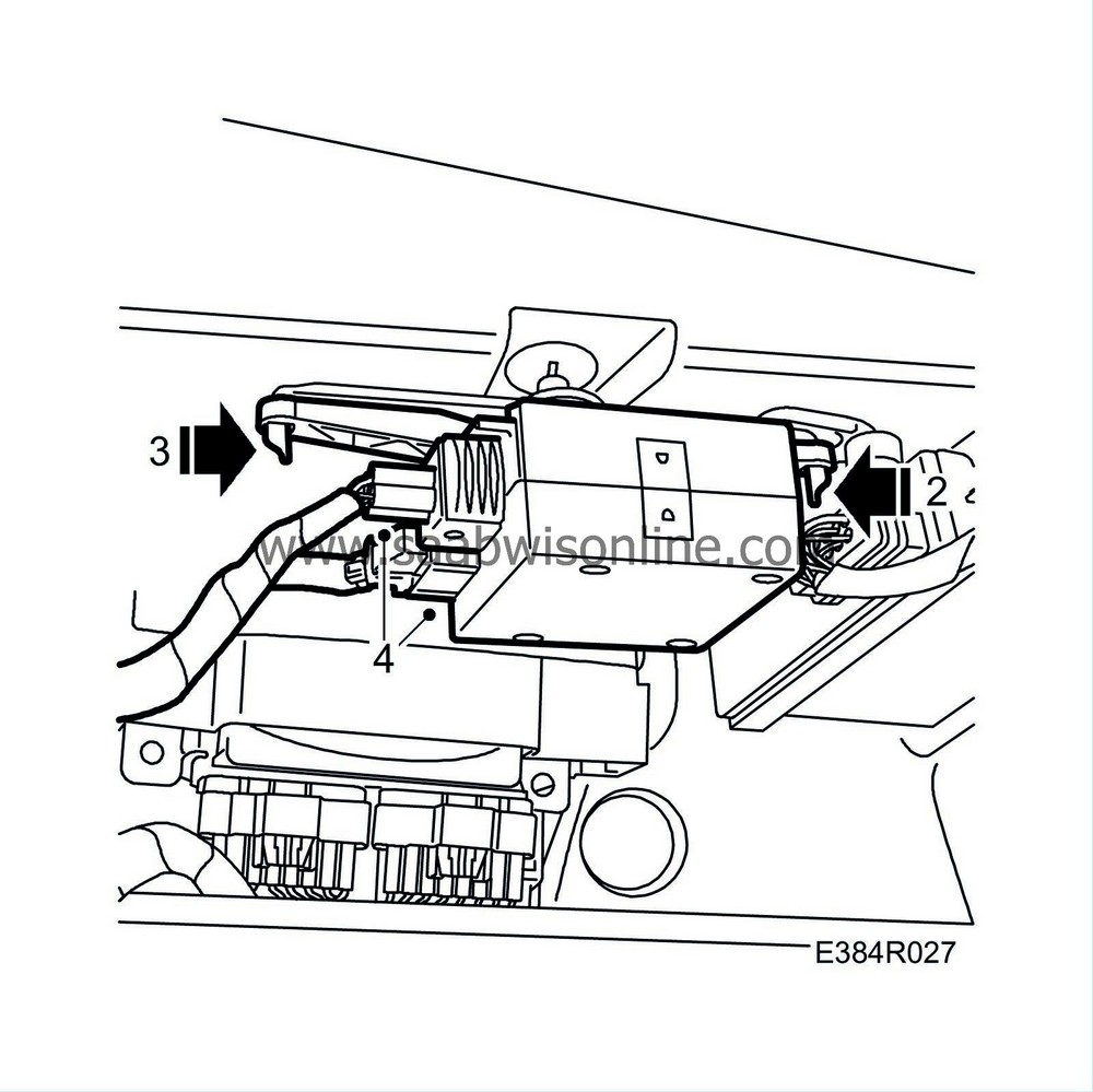
Press the bracket to the left and undo the right-hand catch.
|
|
3.
|
Remove the bracket by undoing the left-hand catch.
|
To fit
|
1.
|
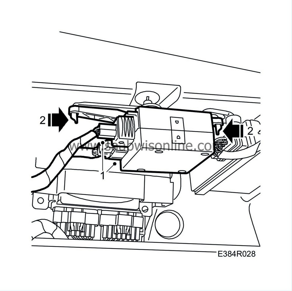
Connect the connector.
|
|
3.
|
Fit the glove box. See WIS: 8. Body - Interior equipment - Adjustment/Replacement - Glove box.
|
Signal converter, I-bus
To remove
|
1.
|
Remove the main unit, Audio. See pages 7 and 9.
|
|
2.
|
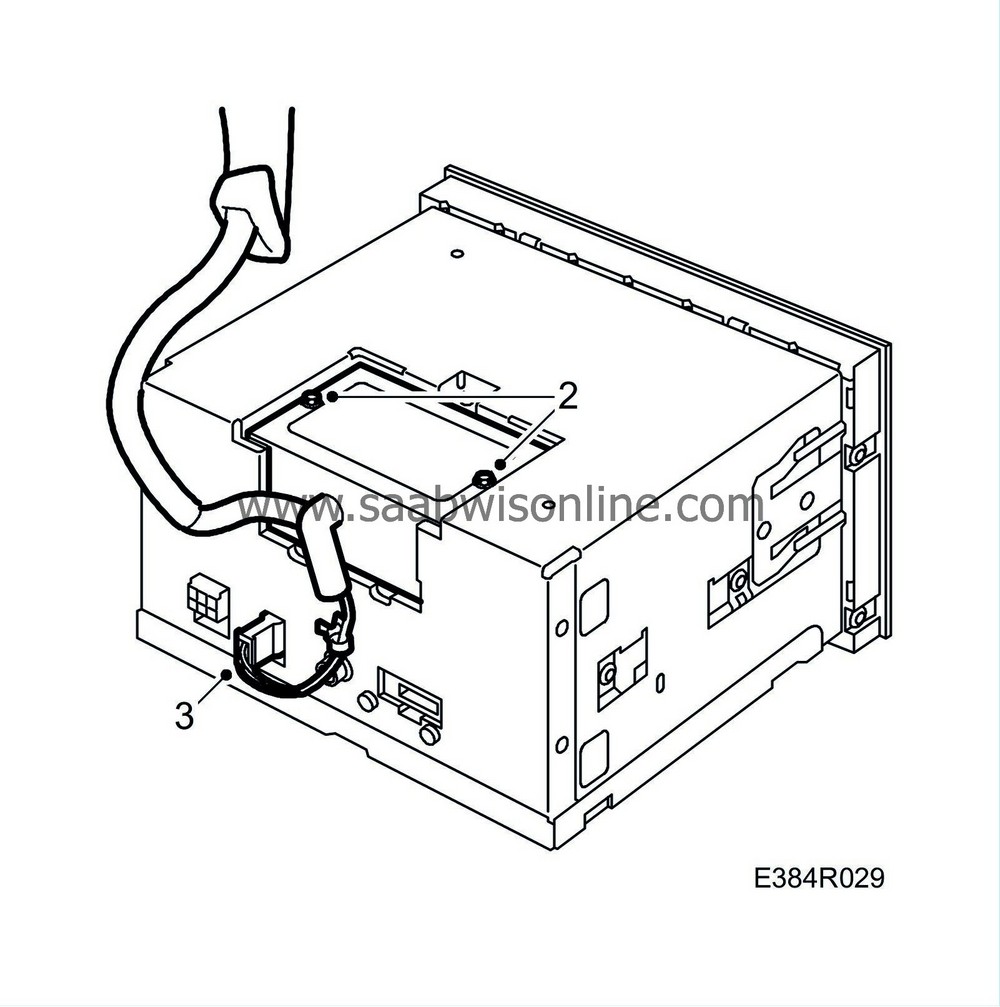
Remove the signal converter screws.
|
|
3.
|
Remove the signal converter.
|
To fit
|
1.
|
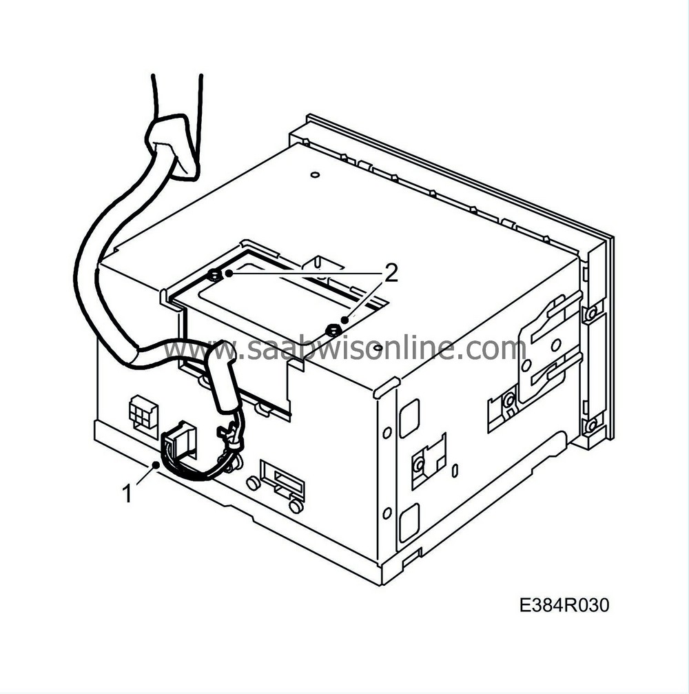
Align the signal converter.
|
|
2.
|
Fit the signal converter screws.
|
|
3.
|
Fit the main unit, Audio. See pages 8 and 10.
|
|
Calculated arrival time unrealistic.
|
Fault symptom
Calculated arrival time does not match the stated route distance and car speed.
Input requirements
The car is driven above 20 km/h.
GPS reception > 2.
One destination is entered.
Diagnostic help
Check that the average speed is correctly set.
See also description of read values under ”Troubleshooting, general” for more information.
|
The display is completely black.
|
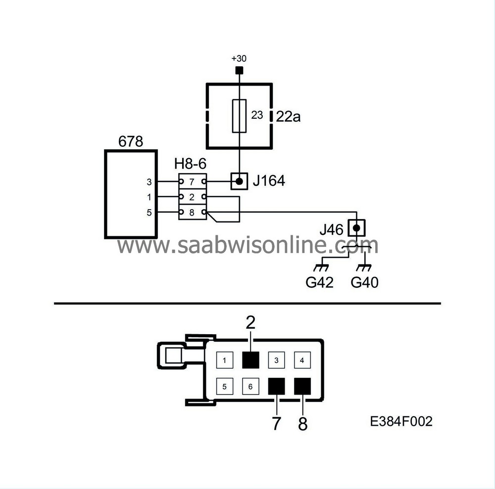
Fault symptom
The display is black in one or more menus.
Input requirements
Turn Ignition On.
Criteria
Nav/Tele switch must be connected. There must be voltage feed and grounding. Also check both connectors with a view to loose pins and oxide.
Diagnostic help
Reset the system before starting troubleshooting.
Check the connectors for oxidation and loose pins. Jiggle the wiring harness too at several points and in several directions to detect intermittent faults and short circuits.
See also description of read values under ”Troubleshooting, general” for more information.
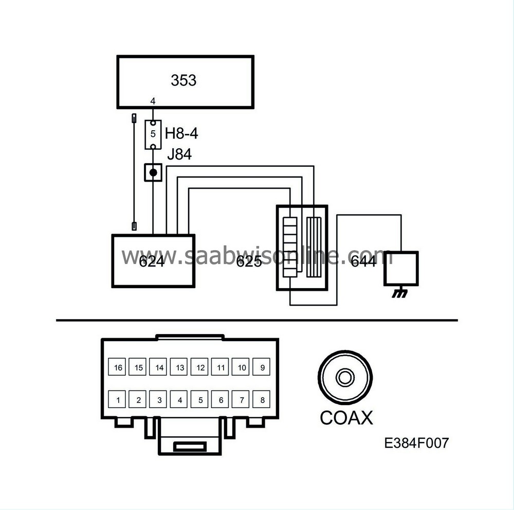
Fault symptom
None or only a few channels remain in the memory.
Input requirements
Turn Ignition On.
Criteria
Nav/Tele switch must be connected. There must be voltage feed and grounding. Also check both connectors with a view to loose pins and oxide.
Diagnostic help
CD and navigation function as normal.
Reset the system before starting troubleshooting and carry out recalibration.
Check the connectors for oxidation and loose pins. Jiggle the wiring harness too at several points and in several directions to detect intermittent faults and short circuits.
See also description of read values under ”Troubleshooting, general” for more information.
|
Poor touch screen functionality.
|
Fault symptom
One or more memory buttons not working.
Input requirements
Turn Ignition On.
Criteria
Nav/Tele switch must be connected. There must be voltage feed and grounding. Also check both connectors with a view to loose pins and oxide.
Diagnostic help
Steering wheel controls are working.
Reset the system before starting troubleshooting and carry out recalibration.
See also description of read values under ”Troubleshooting, general” for more information.
|
The vehicle marker on the map does not follow the car
|

Fault symptom
The marker does not follow the route the car is driving.
Input requirements
The car is driven above 20 km/h.
GPS reception > 2.
Diagnostic help
Check the speed indicator in the navigation system while driving.
Reset the system before starting troubleshooting and carry out recalibration.
Check the connectors for oxidation and loose pins. Jiggle the wiring harness too at several points and in several directions to detect intermittent faults and short circuits.
See also description of read values under ”Troubleshooting, general” for more information.
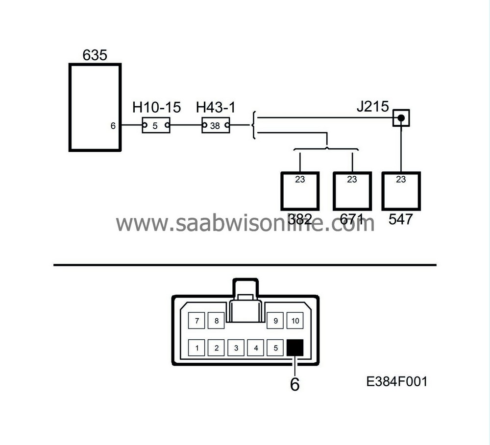
Fault symptom
Speed signal in the display does not correspond with the car's speedometer.
Input requirements
The car is driven above 20 km/h.
GPS reception > 2.
Diagnostic help
Check the speed indicator in the navigation system while driving.
Reset the system before starting troubleshooting and carry out recalibration.
See also description of read values under ”Troubleshooting, general” for more information.

Fault symptom
No image on the screen in any mode.
The system can be shutdown while driving and restarted once by pressing on/off. It will then work for a maximum of 45 minutes and with then not work.
Input requirements
Turn Ignition On.
Criteria
Nav/Tele switch must be connected. There must be voltage feed and grounding. Also check both connectors with a view to loose pins and oxide.
Diagnostic help
Reset the system before starting troubleshooting and carry out recalibration.
Check the connectors for oxidation and loose pins. Jiggle the wiring harness too at several points and in several directions to detect intermittent faults and short circuits.
See also description of read values under ”Troubleshooting, general” for more information.
|
No image on the screen in navigation mode.
|
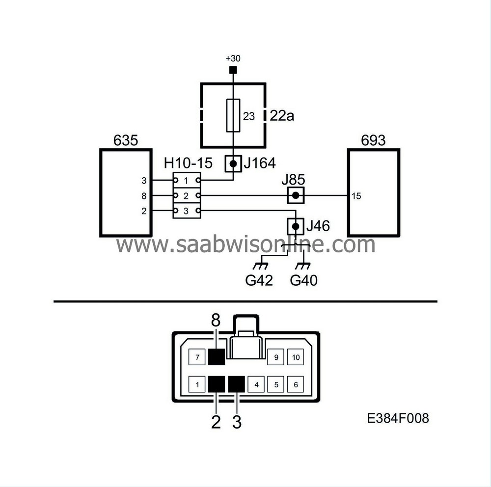
Fault symptom
No image on the screen.
Input requirements
Turn Ignition On.
Criteria
Nav/Tele switch must be connected. There must be voltage feed and grounding. Also check both connectors with a view to loose pins and oxide.
Diagnostic help
Correct image in radio and CD modes.
Reset the system before starting troubleshooting and carry out recalibration.
Check the connectors for oxidation and loose pins. Jiggle the wiring harness too at several points and in several directions to detect intermittent faults and short circuits.
See also description of read values under ”Troubleshooting, general” for more information.
|
None or poor sound with all functions
|

Fault symptom
None or poor sound from one or more loudspeakers.
Input requirements
Turn Ignition On.
Radio reception
Criteria
Nav/Tele switch must be connected. There must be voltage feed and grounding. Also check both connectors with a view to loose pins and oxide.
Diagnostic help
Reset the system before starting troubleshooting and carry out recalibration.
Check the connectors for oxidation and loose pins. Jiggle the wiring harness too at several points and in several directions to detect intermittent faults and short circuits.
See also description of read values under ”Troubleshooting, general” for more information.
|
None or poor sound when using the CD changer
|

Fault symptom
None or poor sound from one or more loudspeakers when playing CD discs.
Input requirements
Turn Ignition On.
Criteria
Nav/Tele switch must be connected. There must be voltage feed and grounding. Also check both connectors with a view to loose pins and oxide.
Diagnostic help
Sound works correctly in radio mode.
Reset the system before starting troubleshooting and carry out recalibration.
Check the connectors for oxidation and loose pins. Jiggle the wiring harness too at several points and in several directions to detect intermittent faults and short circuits.
See also description of read values under ”Troubleshooting, general” for more information.
|
None or poor sound when using navigation
|
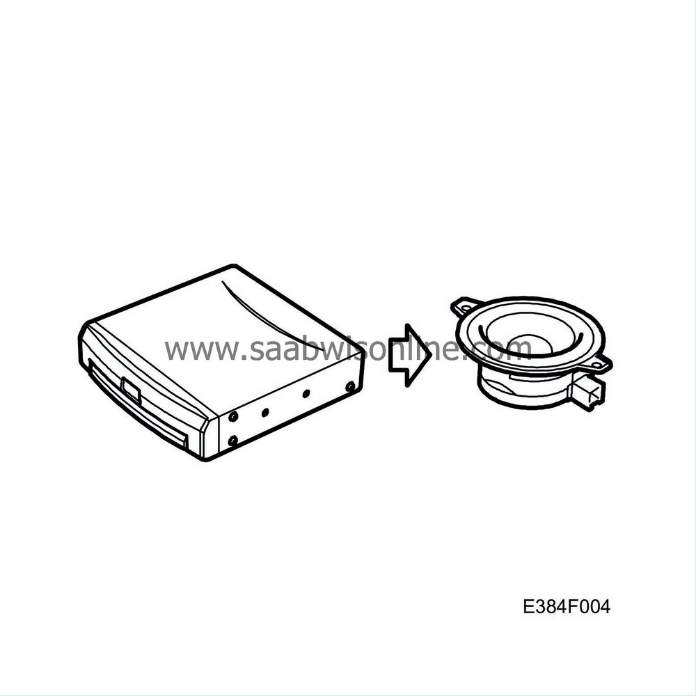
Fault symptom
None or poor sound from one or more loudspeakers when using navigation.
Input requirements
Turn Ignition On.
Criteria
Nav/Tele switch must be connected. There must be voltage feed and grounding. Also check both connectors with a view to loose pins and oxide.
Diagnostic help
Sound works properly in radio mode.
Reset the system before starting troubleshooting and carry out recalibration.
Check the connectors for oxidation and loose pins. Jiggle the wiring harness too at several points and in several directions to detect intermittent faults and short circuits.
See also description of read values under ”Troubleshooting, general” for more information.
|
None or poor sound when using the radio
|
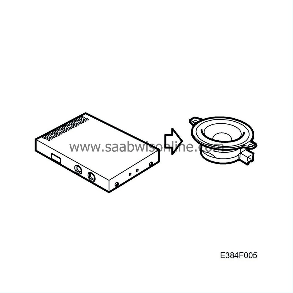
Fault symptom
None or poor sound from one or more loudspeakers when using the radio.
Input requirements
Turn Ignition On.
Radio reception
Criteria
Nav/Tele switch must be connected. There must be voltage feed and grounding. Also check both connectors with a view to loose pins and oxide.
Diagnostic help
Sound works properly with CD discs.
Reset the system before starting troubleshooting and carry out recalibration.
Check the connectors for oxidation and loose pins. Jiggle the wiring harness too at several points and in several directions to detect intermittent faults and short circuits.
See also description of read values under ”Troubleshooting, general” for more information.
|
Steering wheel controls do not work
|
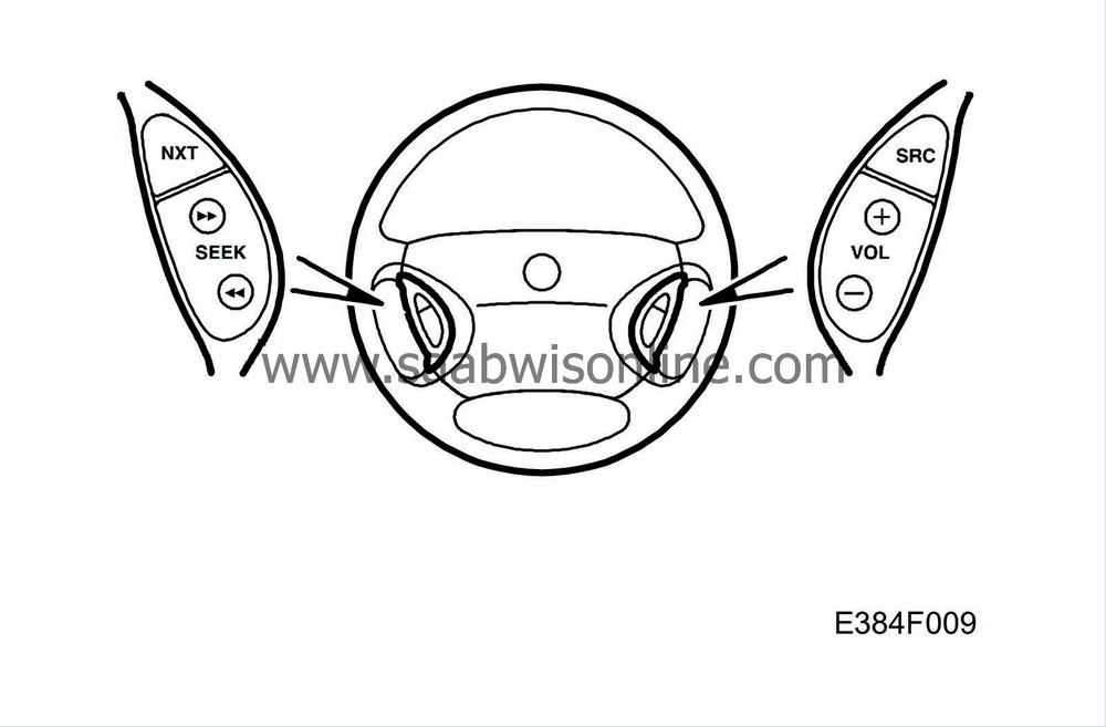
Fault symptom
Steering wheel controls do not work.
Input requirements
Turn Ignition On.
Criteria
Nav/Tele switch must be connected. There must be voltage feed and grounding. Also check both connectors with a view to loose pins and oxide.
Diagnostic help
Touch screen functions correctly.
Faults may exist on the Night Panel function.
Reset the system before starting troubleshooting and carry out recalibration.
Check the connectors for oxidation and loose pins. Jiggle the wiring harness too at several points and in several directions to detect intermittent faults and short circuits.
See also description of read values under ”Troubleshooting, general” for more information.
|
Steering wheel calculation does not work
|

Fault symptom
Navigation assistance does not work.
Input requirements
The car is driven above 20 km/h.
GPS reception > 2.
Criteria
Nav/Tele switch must be connected. There must be voltage feed and grounding. Also check both connectors with a view to loose pins and oxide.
Diagnostic help
Check the speed indicator in the navigation system while driving.
Reset the system before starting troubleshooting and carry out recalibration.
Check the connectors for oxidation and loose pins. Jiggle the wiring harness too at several points and in several directions to detect intermittent faults and short circuits.
See also description of read values under ”Troubleshooting, general” for more information.

Fault symptom
No navigation functions work.
Input requirements
Turn Ignition On.
Criteria
The DVD disc is positioned correctly in the navigation unit and is undamaged.
Diagnostic help
Everything else functions as normal.
Reset the system before starting troubleshooting and carry out recalibration.
Check the connectors for oxidation and loose pins. Jiggle the wiring harness too at several points and in several directions to detect intermittent faults and short circuits.
See also description of read values under ”Troubleshooting, general” for more information.
|
Night Panel does not work
|
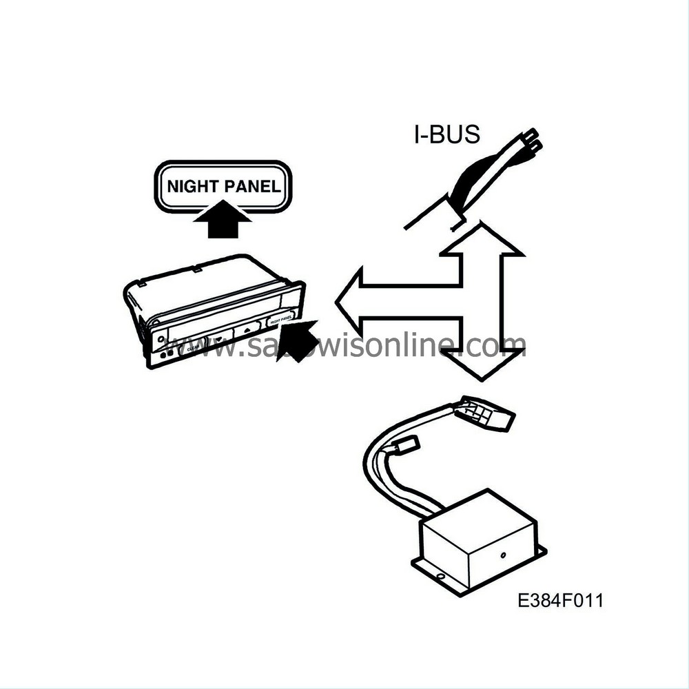
Fault symptom
The display does not blacken when Night Panel is activated.
Input requirements
Turn Ignition On.
Light switch in position 3.
Diagnostic help
Night Panel works as normal for the other functions.
Can also be poor functioning of the steering wheel controls.
See also description of read values under ”Troubleshooting, general” for more information.
|
Troubleshooting - Poor radio reception
|
|
1.
|
Checking installation
Check the radio antenna connection to the main audio unit.
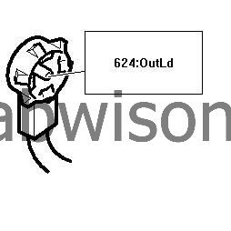
Is the function correct?
If
No
, see point 19.
If
Yes
, see point 20.
|
|
2.
|
Checking the antenna connection
Check the radio antenna connection to the main audio unit.
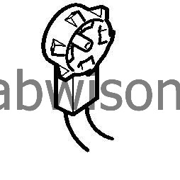
Check the connector for oxidation or loose pins. Jiggle also the wiring harness at several points to detect intermittent breaks or short circuits.
Is the function correct?
If
No
, see point 3.
If
Yes
, see point 4.
|
|
3.
|
Checking the antenna connection
Rectify the fault.

See point 16.
|
|
4.
|
Checking the antenna cable.
Undo the connector: Radio antenna amplifier, signal output 624
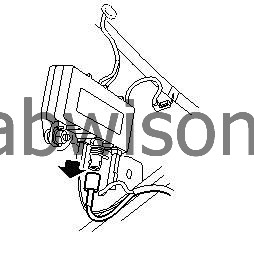
Check the conductor insulation.
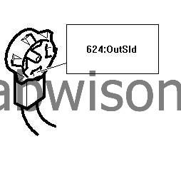

Is the function correct?
If
No
, see point 5.
If
Yes
, see point 6.
|
|
5.
|
Checking the antenna cable.
Replace the antenna cable.
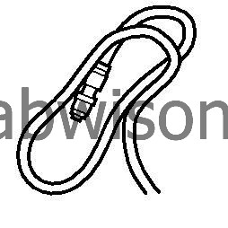
See point 16.
|
|
6.
|
Checking the antenna cable.
Check the conductor insulation.


Is the function correct?
If
No
, see point 5.
If
Yes
, see point 7.
|
|
7.
|
Checking the antenna cable.
Make a connection between the coaxial cable centre conductor and the cable screen.
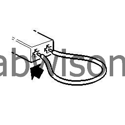
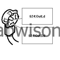
OutLd

OutSld Measure resistance between.
The value should be 0-2 Ohm.
Is the function correct?
If
No
, see point 5.
If
Yes
, see point 8.
|
|
8.
|
Component replacement
Replace radio antenna amplifier.

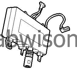
See point 16.
|
|
9.
|
Checking the window antennas
Undo the connector: Radio amplifier, FM1 624.

Undo the connector: Radio antenna ground filter 644.
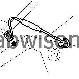
Measure resistance between.
FM1
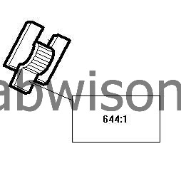
1 The value should be 0-1 Ohm.
Is the function correct?
If
No
, see point 10.
If
Yes
, see point 11.
|
|
10.
|
Checking the window antennas
Repair the window antenna or replace the electrically heated rear window.

See point 16.
|
|
11.
|
Checking the window antennas
Measure the resistance. The value should be OL (infinite).
1 Radio antenna ground filter.
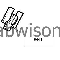
B-

Is the measurement value correct?
If
No
, see point 10.
If
Yes
, see point 12.
|
|
12.
|
Checking the window antennas
Connect the connector: Radio antenna ground filter 644.

Connect the connector: Radio antenna amplifier, FM1 624.

See point 2.
|
|
13.
|
Checking the window antennas
Undo the connector: Radio amplifier, FM1 624.

Undo the connector: Radio antenna ground filter 644.

Measure resistance between.
FM1 Radio antenna amplifier, FM1

1 Radio antenna ground filter
Jiggle the wiring harness at several points and in several directions to detect intermittent faults and short circuits. Note the multimeter, the test lamp or diagnostic tool during the check. Check the contact too for oxidation and loose pins.
The value should be 0-1 Ohm.
Is the function correct?
If
No
, see point 10.
If
Yes
, see point 14.
|
|
14.
|
Checking the window antennas
Measure the resistance. The value should be OL (infinite).
1 Radio antenna ground filter

B-

Jiggle the wiring harness at several points and in several directions to detect intermittent faults and short circuits. Note the multimeter, the test lamp or diagnostic tool during the check. Check the contact too for oxidation and loose pins.
Is the function correct?
If
No
, see point 10.
If
Yes
, see point 15.
|
|
15.
|
Checking the window antennas
Undo the connector: Coaxial cable for AM and FM2 624.

Measure resistance between.
FM2
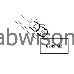
1
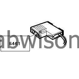
The value should be 5-10 Ohm.
Is the function correct?
If
No
, see point 10.
If
Yes
, see point 12.
|
|
16.
|
Final checks
Clear DTCs in all systems.
Carry out a functionality check.
Is the function correct?
If
No
, see point 17.
If
Yes
, see point 18.
|
|
17.
|
Final checks
See WIS - 'Before changing a control module'.
|
|
18.
|
Final checks
The measures taken are correct.
|
|
19.
|
Procedure
Rectify the fault.
See point 16.
|
|
20.
|
Checking the wiring harness
Remove the component: Radio antenna amplifier
Clean the both of the antenna amplifier ground connections, the area around the stud screws and the screw hole in the body.
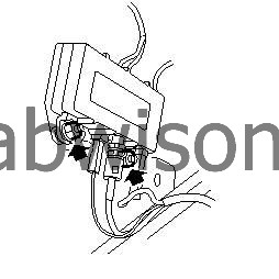
Fit the component: Radio antenna amplifier
The antenna amplifier must be safely grounded by both stud screws.

Undo the connector: Radio antenna amplifier, trigger current input 624
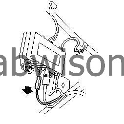
Turn the ignition key to the ON position.

Switch on the main unit.
Connect the test lamp 86 11 857 between pin 1 in the female contact and a safe grounding point.
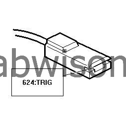

Jiggle the wiring harness at several points and in several directions to detect intermittent faults and short circuits. Note the multimeter, the test lamp or diagnostic tool during the check. Check the contact too for oxidation and loose pins.
The test lamp should light.

Is the function correct?
If
No
, see point 21.
If
Yes
, see point 22.
|
|
21.
|
Wiring procedure
Rectify the wiring between the antenna amplifier's trigger current connection and contact K16, pin 4, on the main unit.
See point 16.
|
|
22.
|
Fault symptom checking
Which function is defective?
AM reception, see point 23.
FM reception, see point 30.
AM and FM reception, see point 30.
|
|
23.
|
Checking the AM antenna connection
Check the two-pin connection to the window antenna.
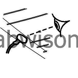
Is the function correct?
If
No
, see point 24.
If
Yes
, see point 25.
|
|
24.
|
Checking the AM antenna connection
Rectify the fault.

See point 16.
|
|
25.
|
Checking the AM antenna
Checking the AM antenna in the rear window.
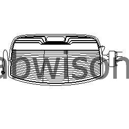
Is the function correct?
If
No
, see point 26.
If
Yes
, see point 27.
|
|
26.
|
Checking the AM antenna
Repair the window antenna or replace the electrically heated rear window.

See point 16.
|
|
27.
|
Checking the antenna cable between the window antenna and the antenna amplifier
Undo the connector: Coaxial cable for AM and FM2 624

Measure the resistance. The value should be OL (infinite).
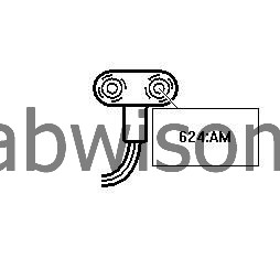

Is the measurement value correct?
If
No
, see point 28.
If
Yes
, see point 29.
|
|
28.
|
Checking the antenna cable between the window antenna and the antenna amplifier
Rectify the wiring between the connector and the antenna amplifier.
See point 16.
|
|
29.
|
Component replacement
Replace radio antenna amplifier.


See point 16.
|
|
30.
|
System selection
Which type of system is the car equipped with?
Antenna system 1, see point 9.
Antenna system 2, see point 13.
|


