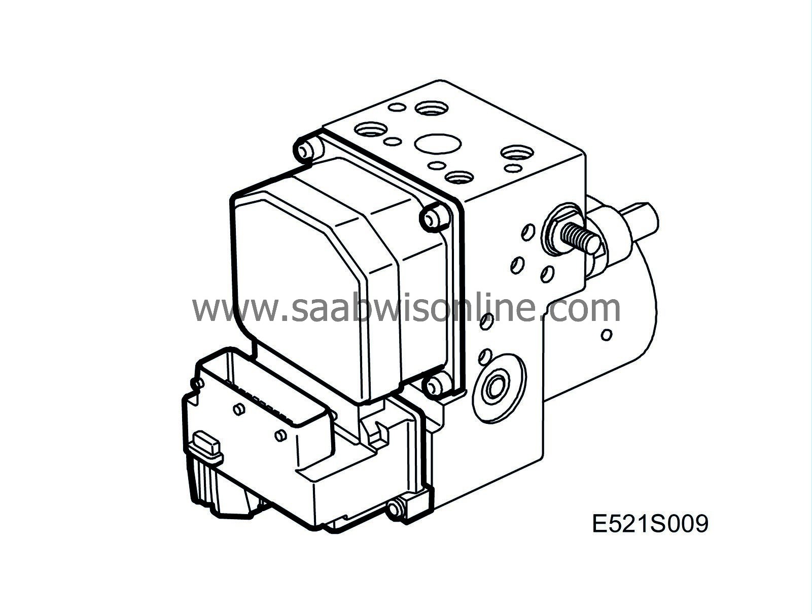
ESP valve block
| ESP valve block |

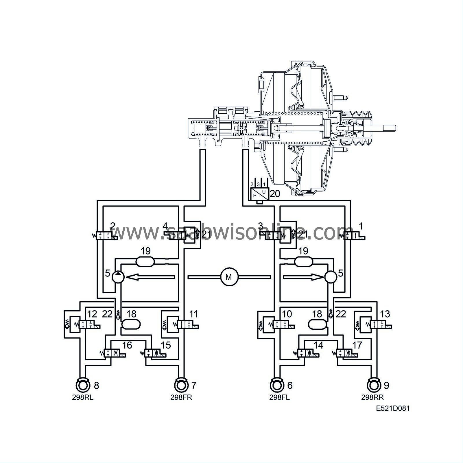
The ESP valve block consists of 12 electromagnetic valves that control the brake pressure to the brakes during ABS, TCS and ESP braking.
The pressure-increase and pressure-reducing valves are the same as in the TC/ABS unit to their design and operation. In order to enable ESP regulation, the valves are connected to the rear wheel brakes and the inlet and outlet valves are also activated during ESP regulation. This arrangement is to enable the brake pressure on all four wheels to be modulated. This solution makes it possible to build up pressure, maintain pressure and reduce pressure individually on all four wheels.
If the driver applies the brakes while ESP regulation is active, the brake pressure sensor will inform the control module of the input brake pressure in the hydraulic unit. With this information, the brake pressure to the wheels not under ESP regulation can be controlled to correspond to the driver's braking force. The wheel under ESP regulation when the brakes are applied is controlled according to the ESP criteria.
See the description and illustrations under as "ESP regulation and brake application".
The pump is active continuously during ESP regulation.
| Diagnostics |
The control module performs a valve test every time the ignition is turned on. The valve tests are carried out simultaneously with the pump motor tests. The valves are activated for 20 ms.
In any event, the ESP, TCS and ABS functions will be disabled and the warning lamps for ABS, brakes, central warning lamp and ESP OFF will be turned on.

| 1. |
Front left pressure-increase valve
|
|
| 2. |
Front right pressure-increase valve
|
|
| 3. |
Pressure reducing valve, front left
|
|
| 4. |
Front right pressure-reducing valve
|
|
| 5. |
Return pump
|
|
| 6. |
Brake caliper, front left
|
|
| 7. |
Brake caliper, front right
|
|
| 8. |
Brake caliper, rear left
|
|
| 9. |
Brake caliper, rear right
|
|
| 10. |
Front left inlet valve
|
|
| 11. |
Front right inlet valve
|
|
| 12. |
Rear left inlet valve
|
|
| 13. |
Rear right inlet valve
|
|
| 14. |
Front left outlet valve
|
|
| 15. |
Front right outlet valve
|
|
| 16. |
Rear left outlet valve
|
|
| 17. |
Rear right outlet valve
|
|
| 18. |
Accumulator chamber
|
|
| 19. |
Pressure chamber
|
|
| 20. |
Brake pressure sensor
|
|
| 21. |
Check valve
|
|
| 22. |
Check valve
|
|
The valve block, which is an integral part of the hydraulic unit, modulates the brake pressure to the calipers when ABS braking and TCS modulation with braking are activated.
The valve block contains 12 solenoid valves: four inlet valves, four outlet valves, two pressure increase valves and two pressure reducing valves. These are arranged as follows: one inlet and one outlet valve for each of the four wheels and one pressure increase and one pressure reducing valve for each of the front wheels. A description of the inlet and outlet valves and their accumulator chambers is given under the heading “Valve block, ABS function”. The valves concerning the TCS function are described here.
The pressure increase valve is normally closed but is opened by the control module to supply the return pump with brake fluid for building up pressure in connection with active TCS modulation.
The pressure-reducing valve is normally open but will be closed during pressure build-up and pressure maintenance, and opened for reducing pressure to maintain the brake pressure, calculated by the control module, at the wheel concerned in connection with active TCS modulation.
The valve block contains 2 check valves for the TCS function. If the driver brakes while TCS modulation is in progress, the TCS function with braking will be disengaged and the braking function will be chosen instead. During the delay which may arise, the check valve mounted parallel with the pressure-reducing valve prevents the braking function from being affected because the check valve leads the brake pressure out to the wheel.
The check valve mounted after the outlet valve prevents the accumulator from being filled with brake fluid.
The return pump is continuously active during TCS modulation.
Diagnostics
The control module performs a valve test each time the ignition is switched on. This test takes place at the same time as the pump-motor test and the valves are actuated for 20 ms.A DTC is generated if one of the components malfunctions. The ESP, TCS and ABS functions will be disabled and the warning lamps for the ABS, foot brake, central warning lamp and ESP OFF switched on.


