Engine block
| Engine block |
| 1. |
Fit
83 94 751 Holder, V6 and Diesel engine
onto the engine and lift the power train over to the
78 74 878 Floor stand.
|
|
| 2. |
Drain the engine oil.
|
|
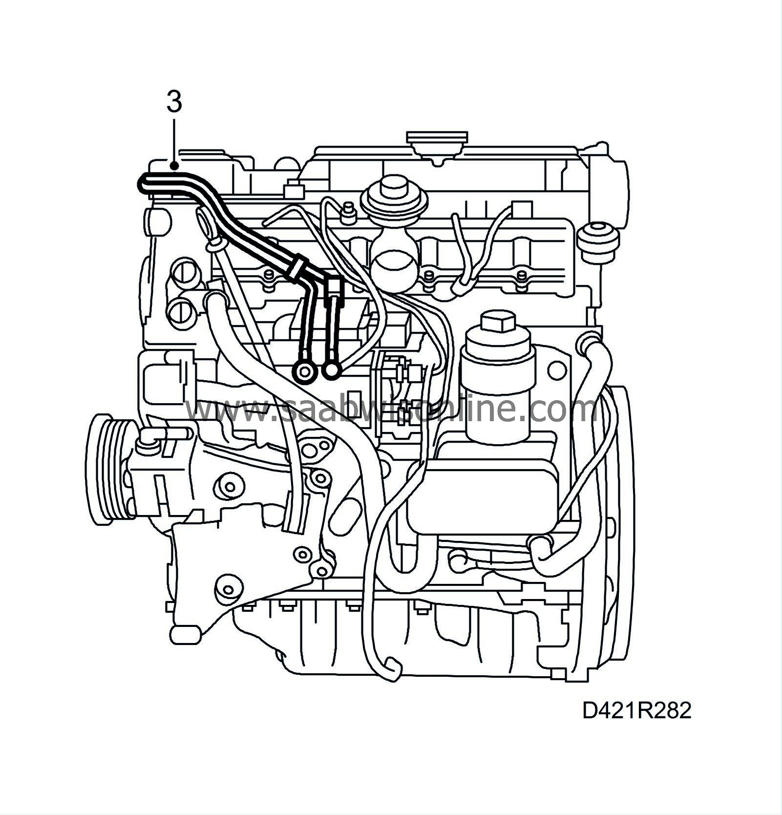
| 3. |
Detach the two fuel lines from the fuel distribution pump.
|
|
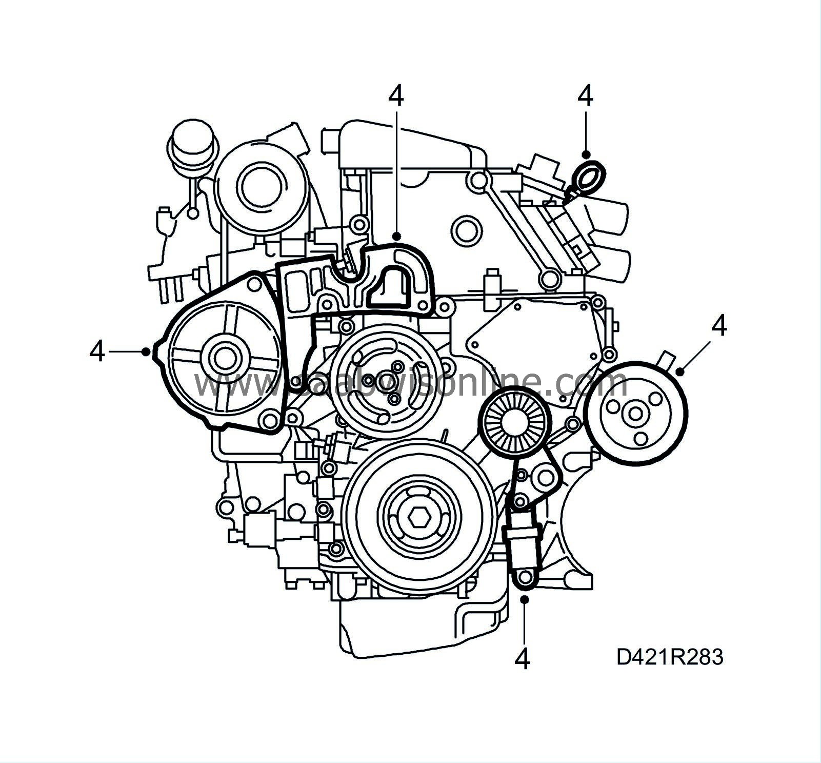
| 4. |
Remove the belt tensioner, take away the generator, engine mounting, dipstick and power steering pump with bracket.
|
|
| 5. |
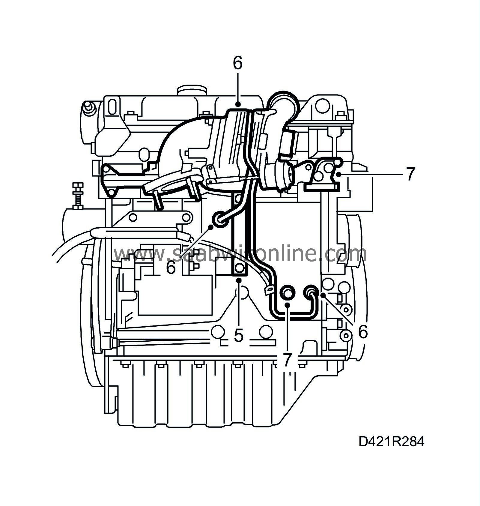
Remove the exhaust manifold support.
|
|
| 6. |
Undo both turbocharger oil pipes from the cylinder block, remove the oil pipe connections from the cylinder block and remove the exhaust manifold with turbocharger.
|
|
| 7. |
Remove the generator bracket and engine oil pressure sensor.
|
|
| 8. |
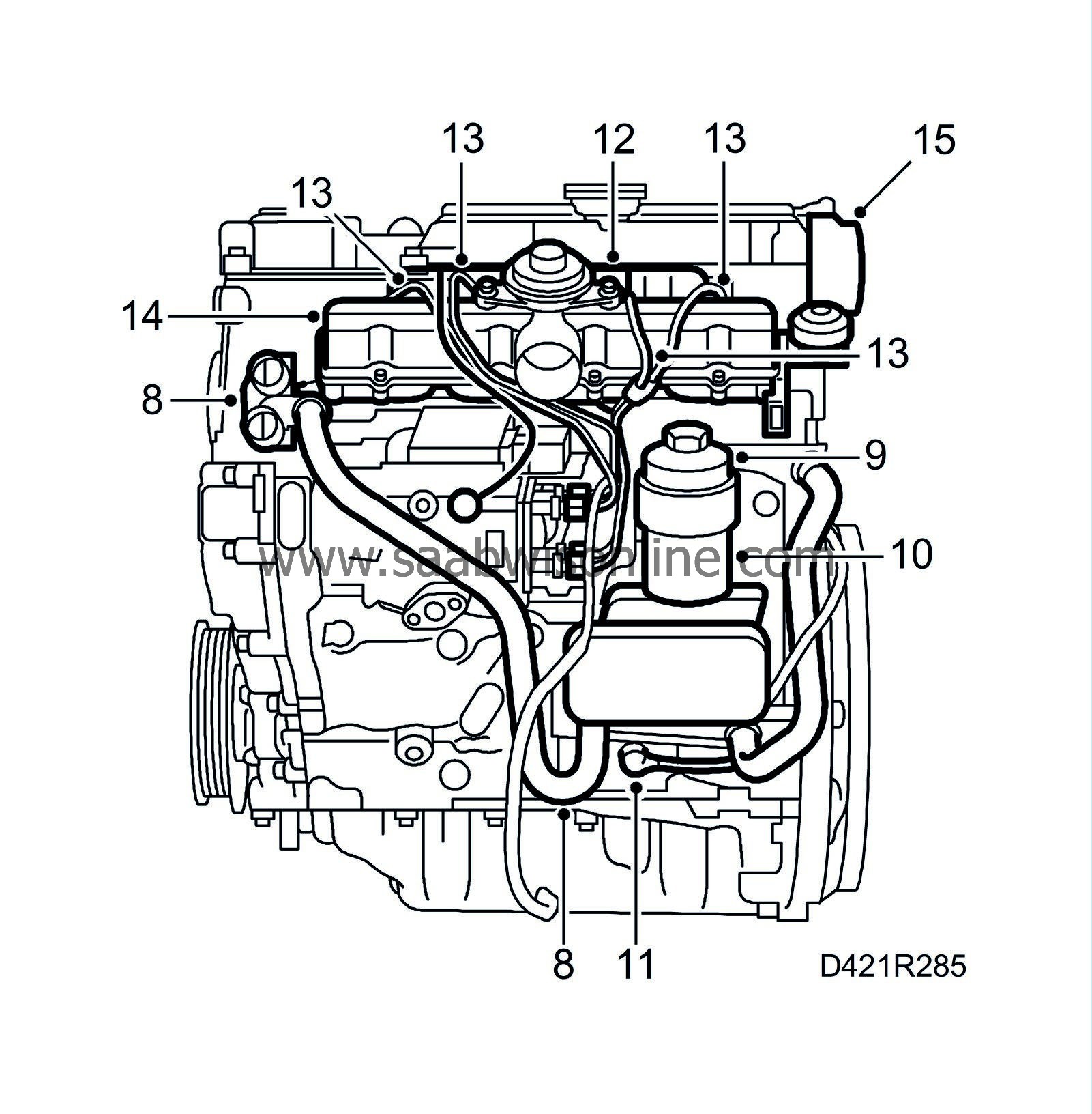
Detach the coolant hose from the thermostat housing and remove the thermostat housing.
|
|
| 9. |
Remove the oil filter housing cover and take out the oil filter.
|
|||||||
| 10. |
Remove the filter housing with heat exchanger and hoses.
|
|
| 11. |
Remove the crankshaft position sensor and the O-ring.
|
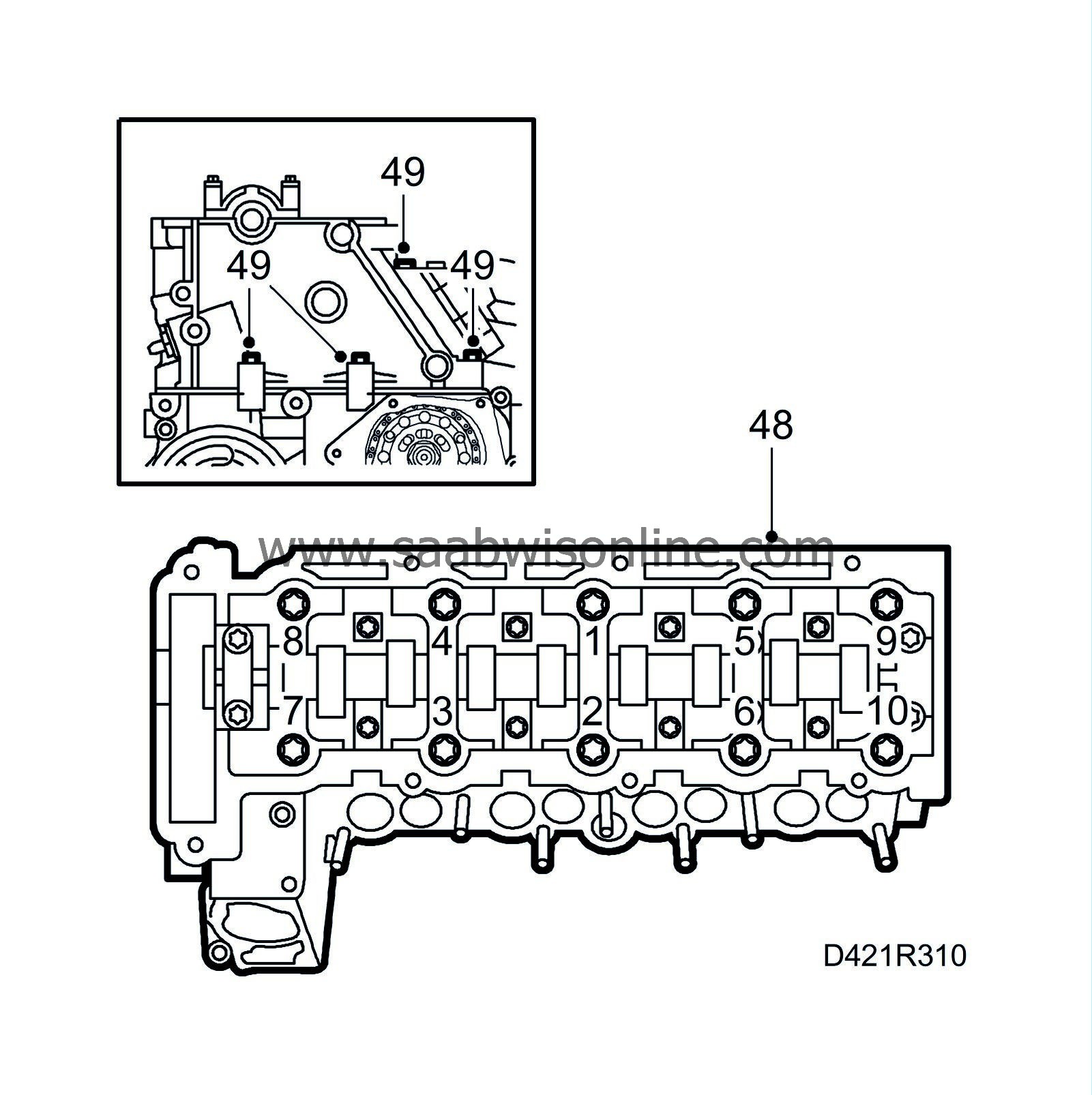
|
| 12. |
Pull loose the fuel return hoses.
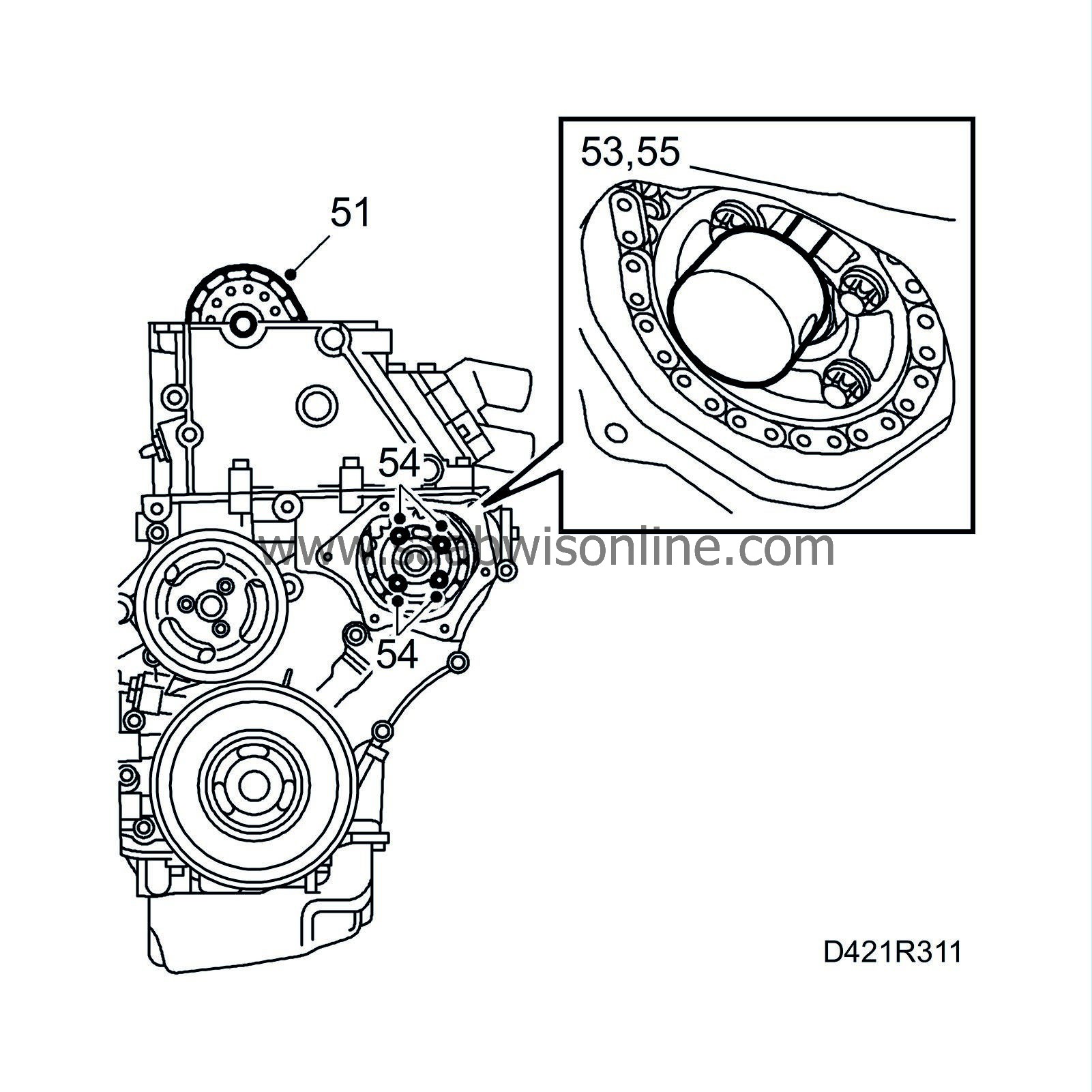
|
|
| 13. |
Make a note of the position of the fuel distribution pipes and their clips, mark the pipes and remove them.
|
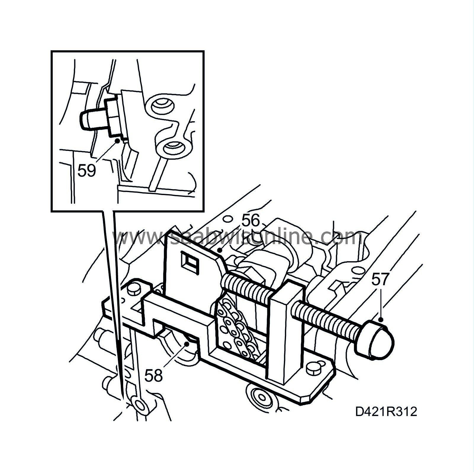
|
| 14. |
Remove the upper part of the intake manifold, take away the gasket and remove the lower part of the intake manifold.
|
|
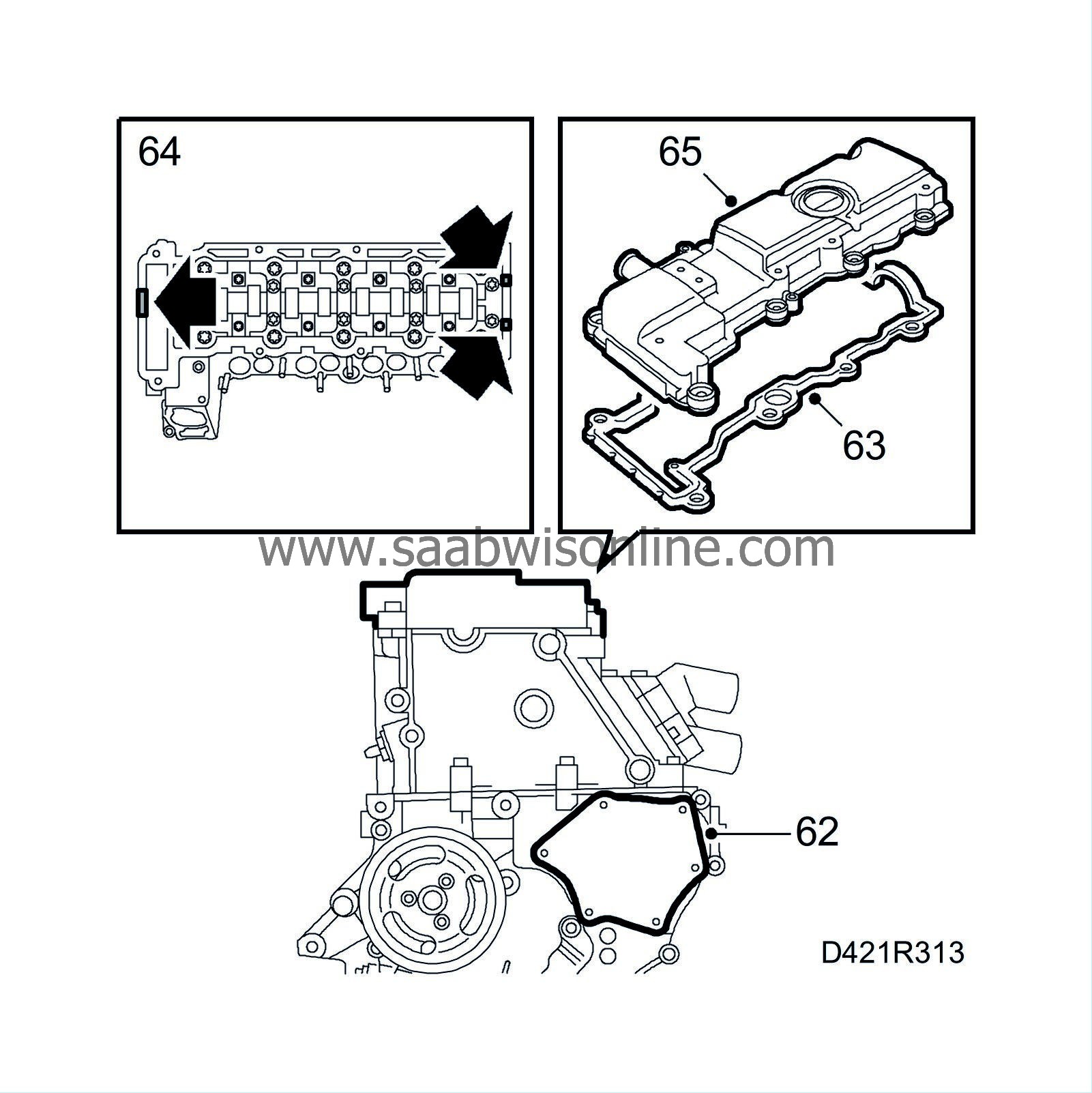
| 15. |
Take away the four vacuum pump retaining bolts and carefully lift off the vacuum pump and its adapter.
|
||||||||||
| 16. |
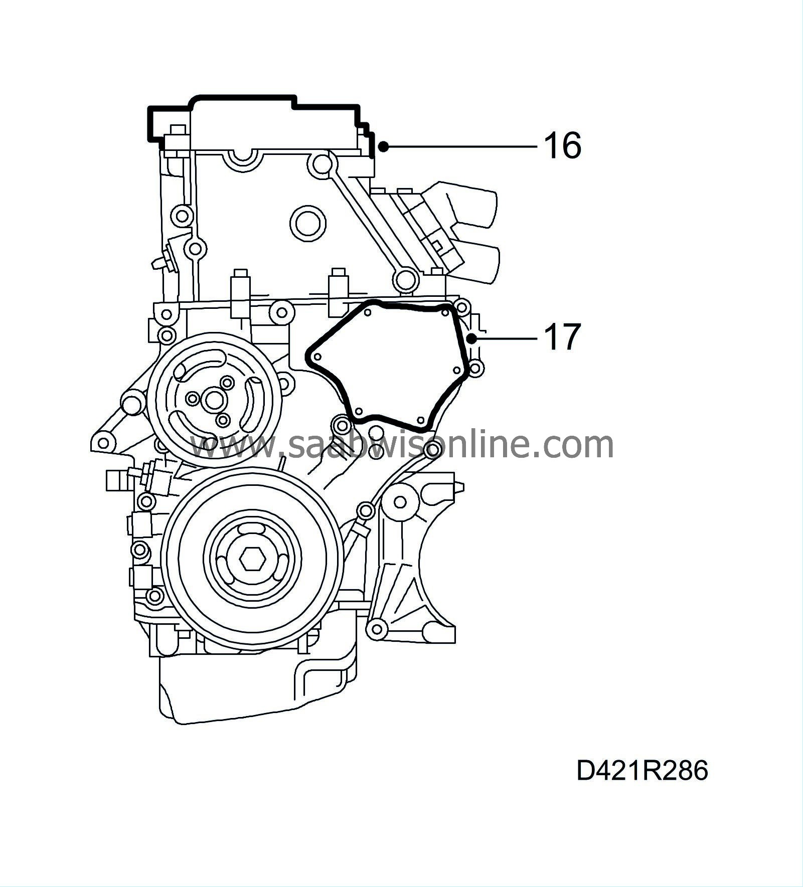
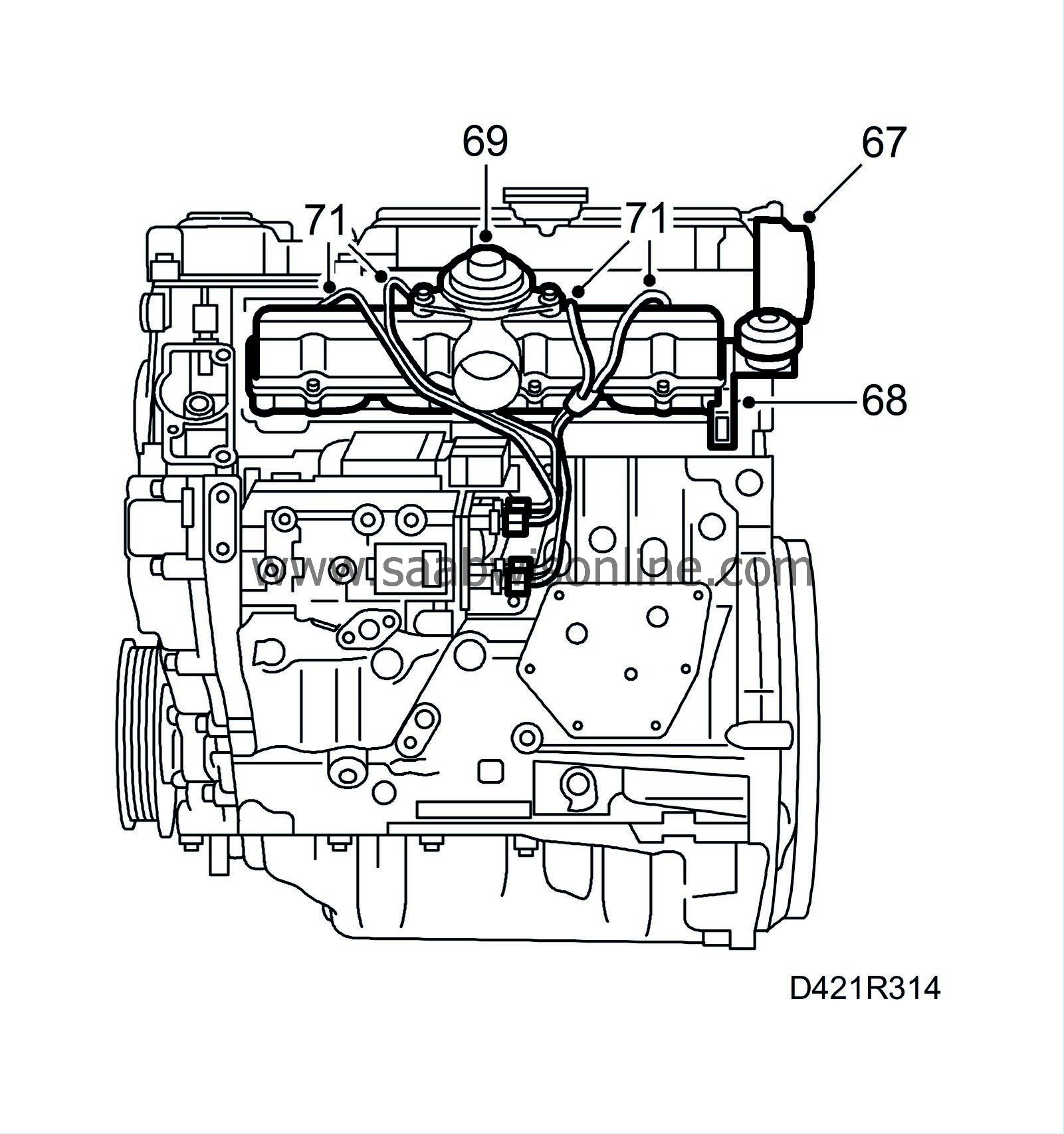
Remove the camshaft cover.
|
|
| 17. |
Remove the bolts on the cover plate, carefully insert a spatula behind the plate and prise it loose carefully.
|
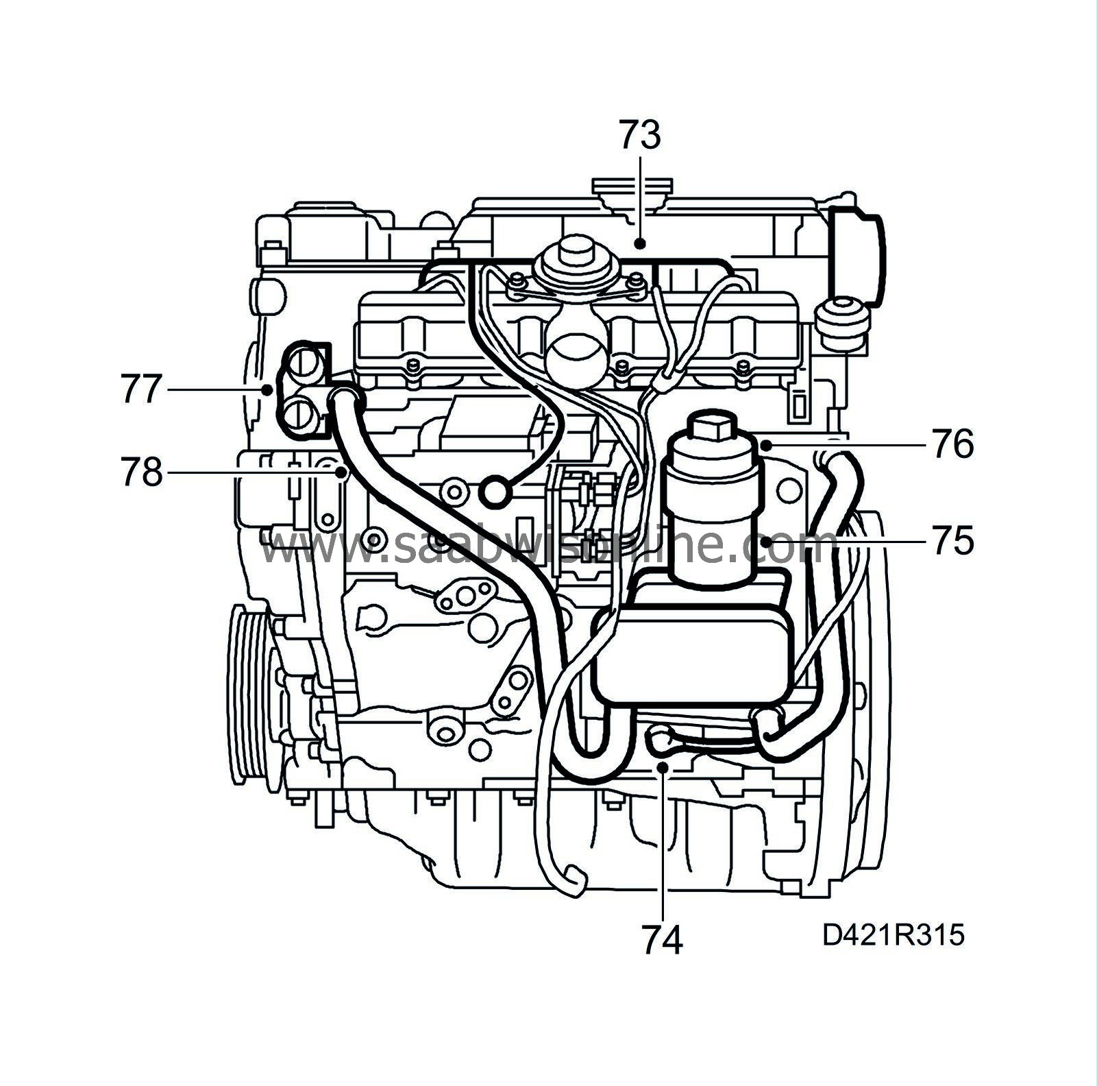
||||||||||
| 18. |
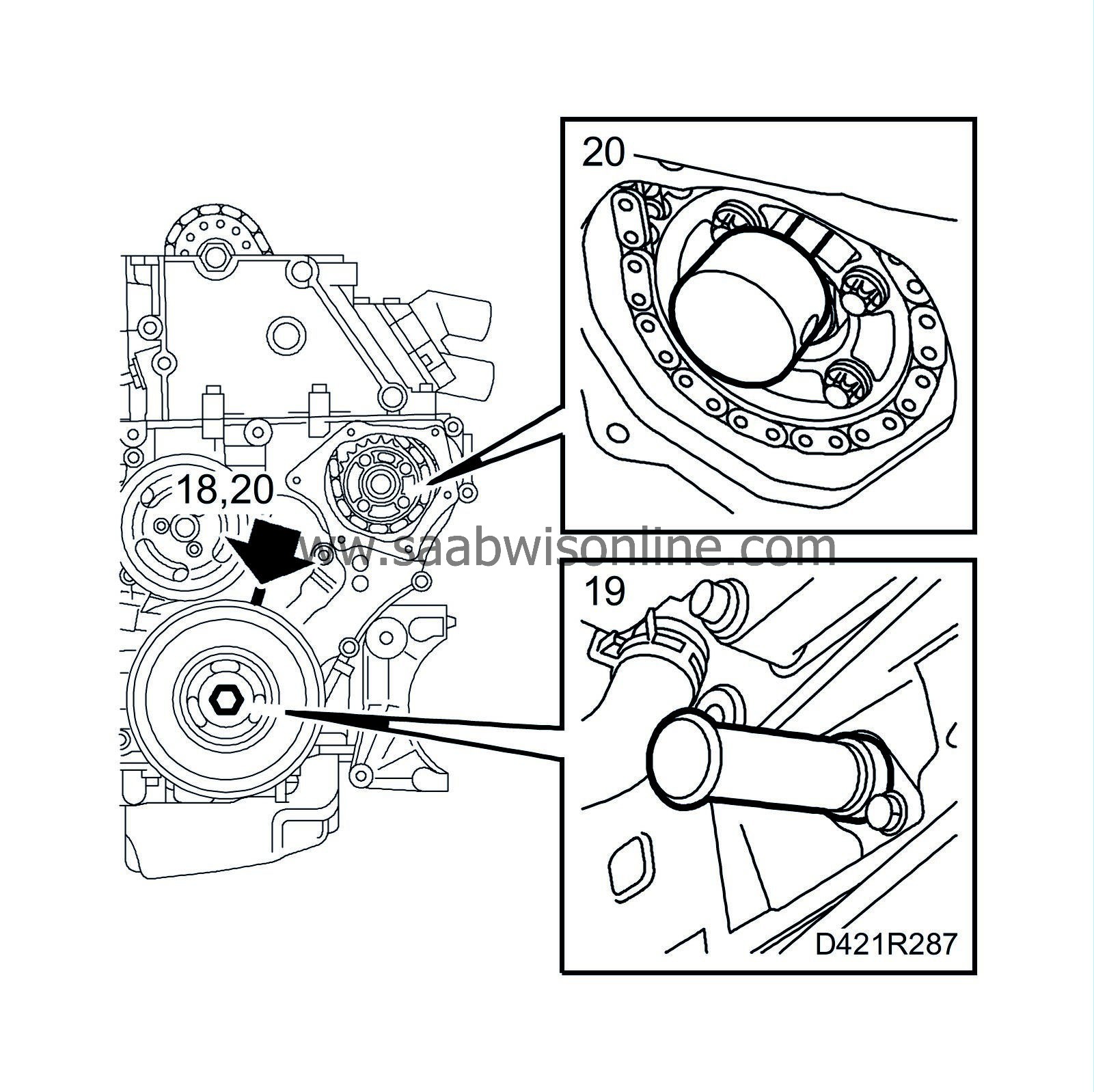
Turn the crankshaft with the help of the belt pulley's central screw to just before the mark for top dead centre in cylinder 1. Make sure that both camshaft lobes for cylinder 1 are pointing up.
|
|
| 19. |
Insert
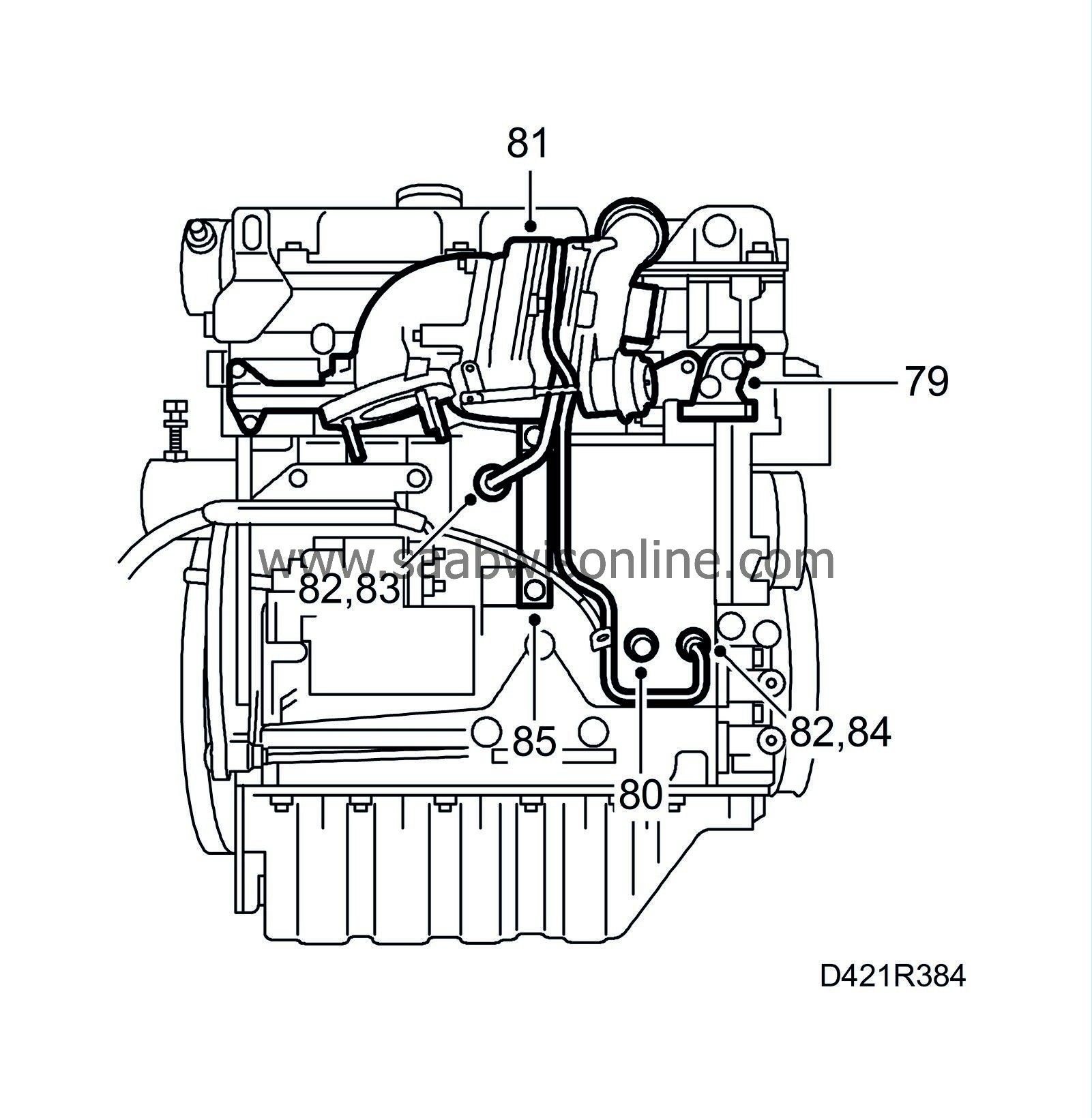
83 95 352 Setting tool, crankshaft
into the hole for the crankshaft position sensor. Push the tool somewhat inward at the same time as the crankshaft is turned to the zero point. The tool will then go into a recess in the crankshaft and lock it.
|
|
| 20. |
Make sure the markings on the crankshaft pulley and the timing cover are in line. The arrow on the single timing chain pulley on the fuel distribution pump must also be in line with the recess in the pump. Position
83 95 337 Setting tool, fuel pump
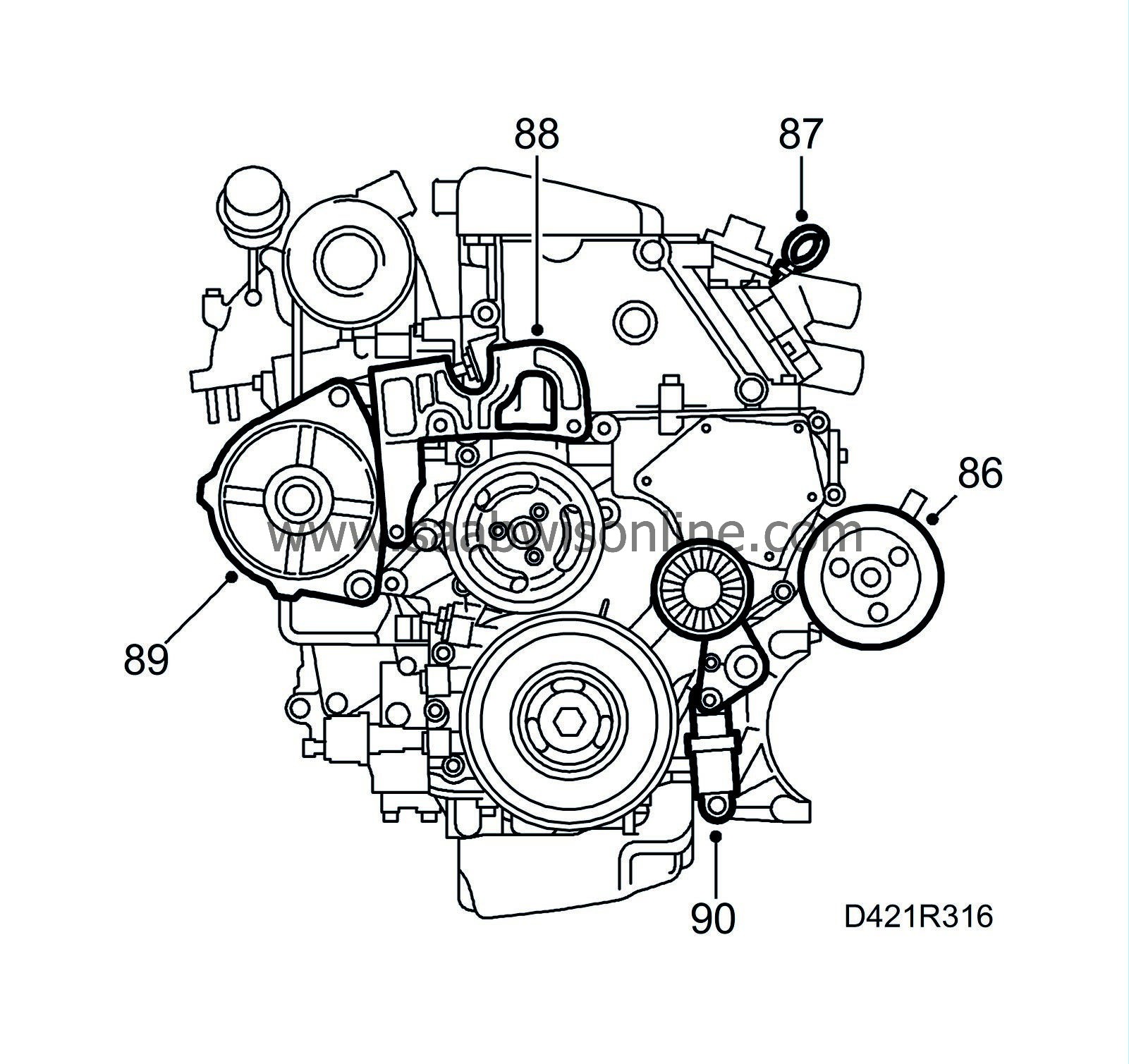
in the hole.
|
|
| 21. |
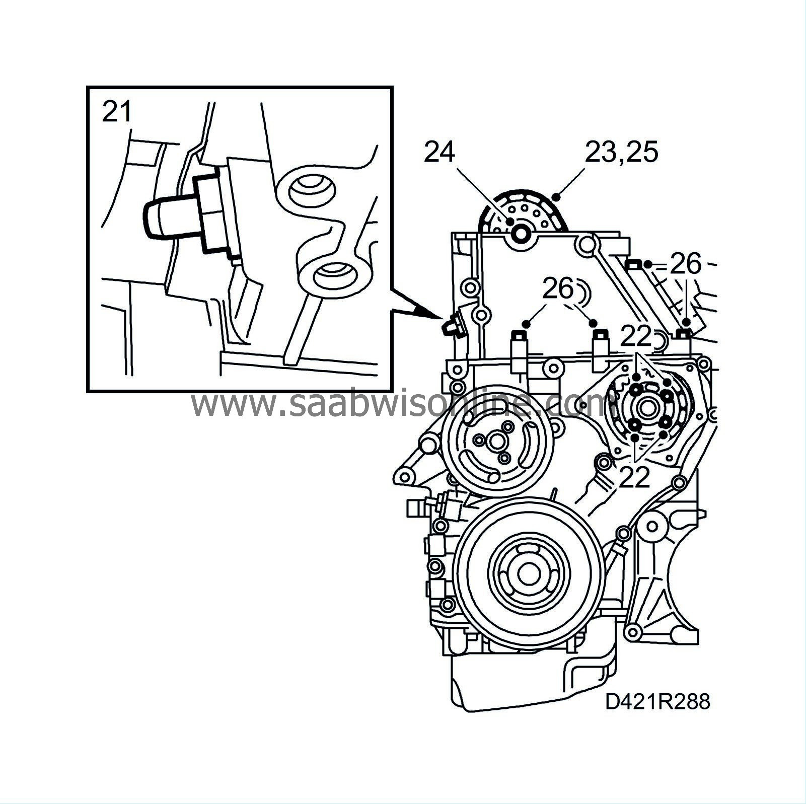
Remove the upper timing chain tensioner.
|
|
| 22. |
Remove
83 95 337 Setting tool, fuel pump
and undo the four bolts for the upper timing chain pulley.
|
||||||||||
| 23. |
Fasten the timing chain to the camshaft sprocket.
|
|
| 24. |
Remove the camshaft sprocket using an open spanner for support in the hexagonal recess on the camshaft.
|
|
| 25. |
Pull up the upper timing chain.
|
|
| 26. |
Remove the four bolts securing the cylinder head to the timing cover.
|
||||||||||
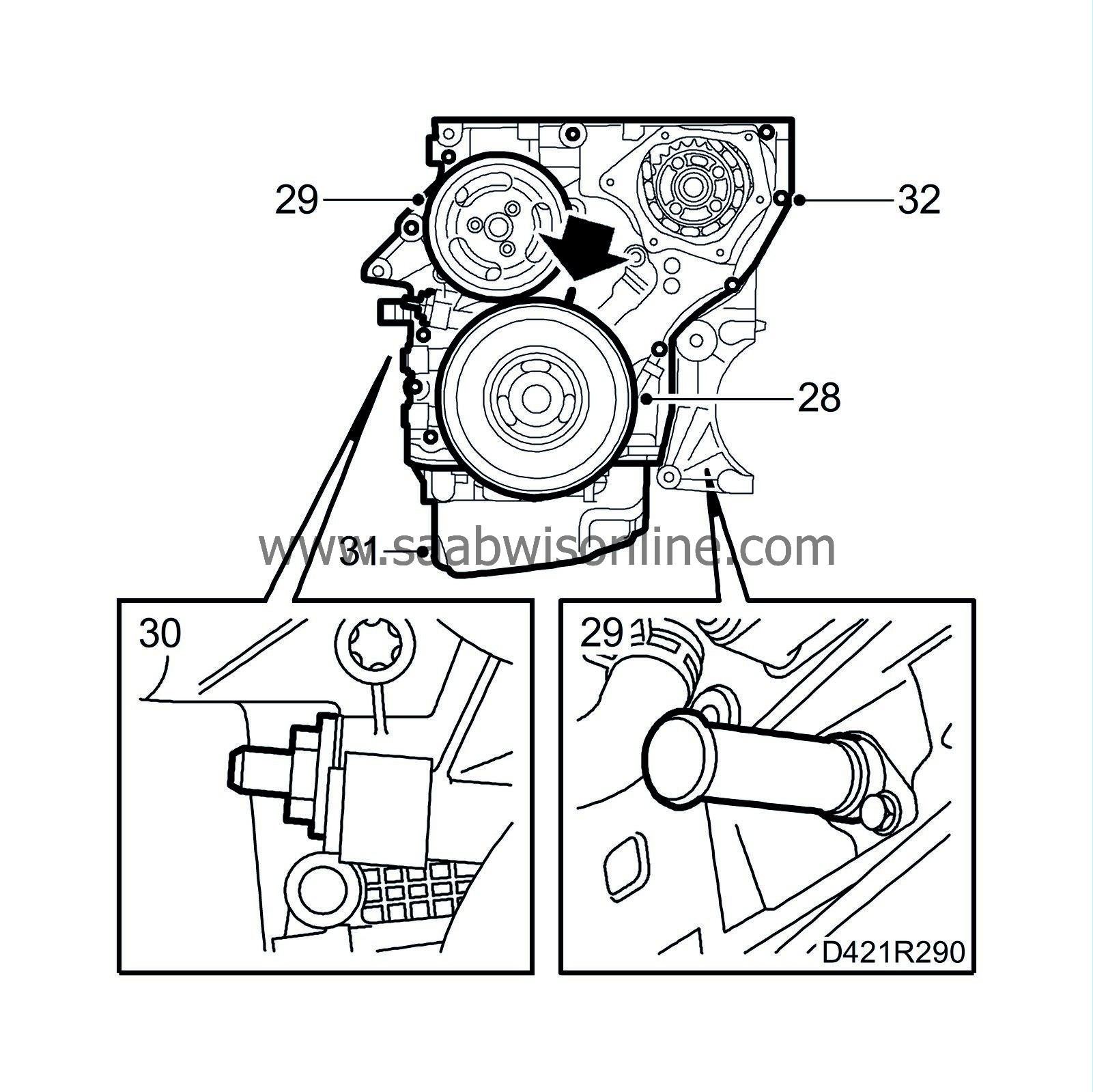
| 28. |
Remove the crankshaft pulley using
83 95 360 Support, crankshaft pulley
for support.
|
|
| 29. |
Remove the coolant pump pulley and
83 95 352 Setting tool, crankshaft
.
|
|
| 30. |
Remove the lower timing chain tensioner.
|
|
| 31. |
Turn the engine and remove the oil sump.
|
||||||||||
| 32. |
Undo all the bolts in the timing cover.
|
||||||||||
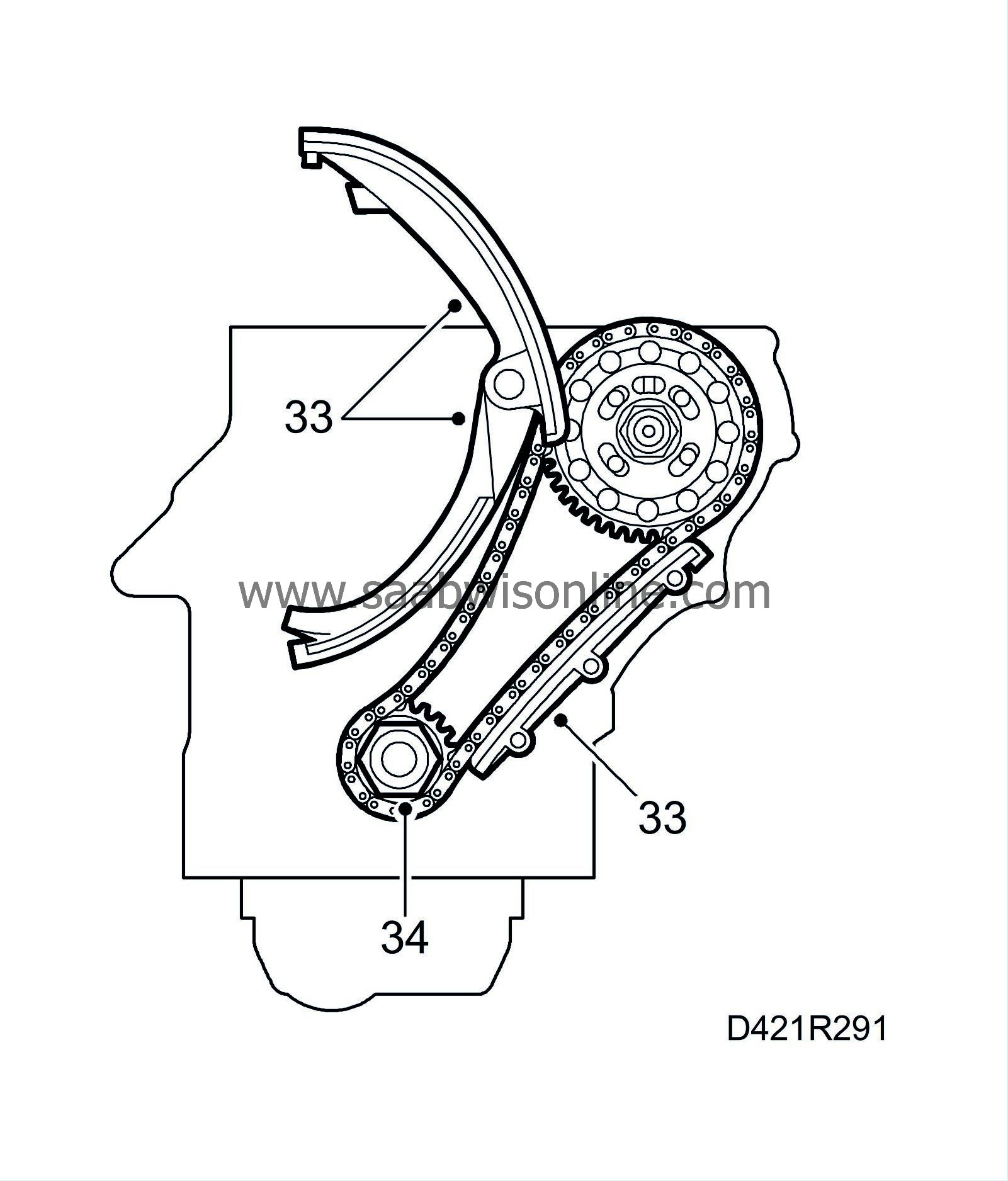
| 33. |
Remove all chain guides.
|
|
| 34. |
Carefully take off the lower timing chain together with the pulley.
|
||||||||||
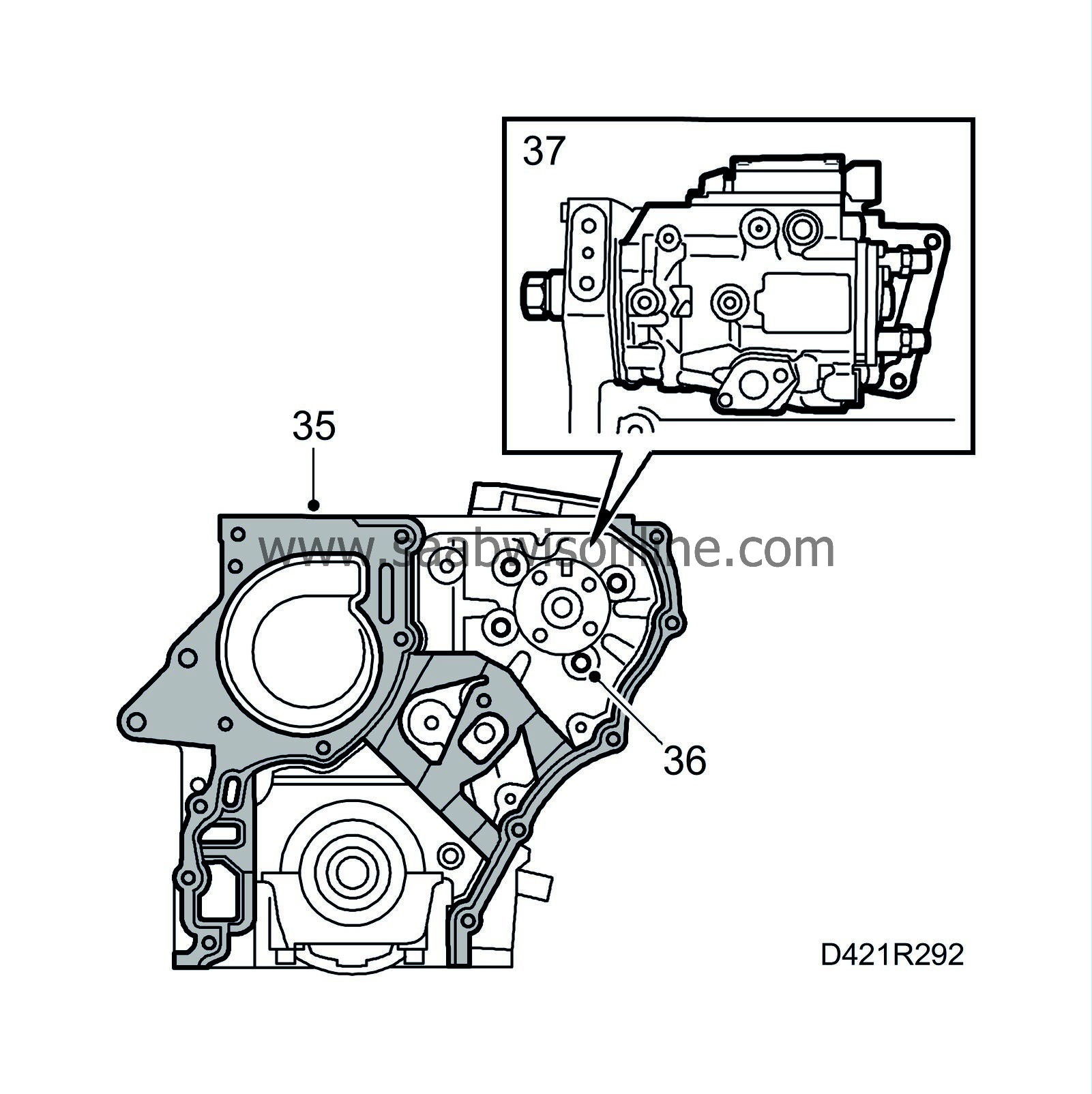
| 35. |
Remove the timing cover gasket.
|
|
| 36. |
Remove the fuel distribution pump retaining bolts on the timing side.
|
|
| 37. |
Remove the bracket from the fuel distribution pump and cylinder block and remove the fuel pump.
|
|
| 38. |
Lock the balancer shafts with
83 95 469 Setting tool, balancer shafts
and remove the cover over the balancer shaft timing chain.
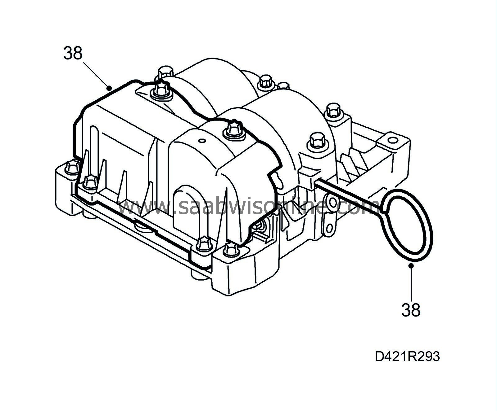
|
|
| 39. |
Move back and lock the balancer shaft chain tensioner and remove the pulley from the balancer shaft.
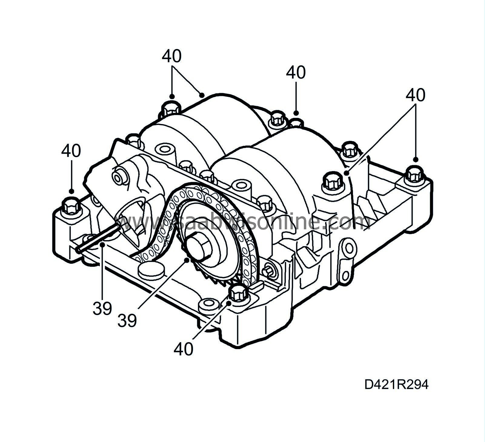
|
|
| 40. |
Undo the 7 outer bolts and remove the balancer shafts as one unit.
|
|
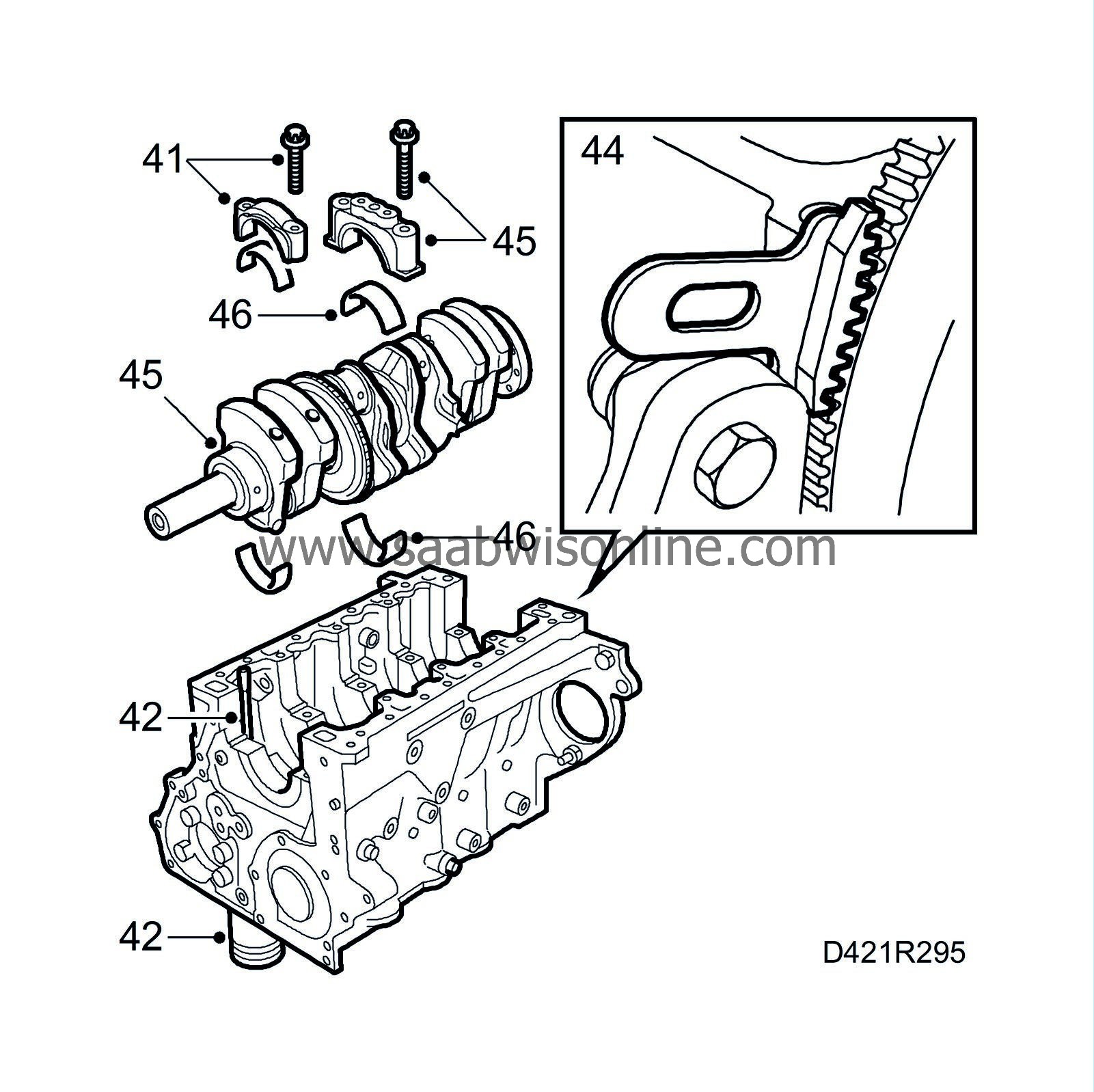
| 42. |
Screw the bolts into the connecting rods and fit
75 19 531 Protective collar (type 10)
onto the studs. Then press or tap the pistons out of the cylinders.
|
|
| 43. |
Remove the pressure plate and clutch plate.
|
|
| 44. |
Fit
83 94 868 Flywheel locking attachment
and remove the flywheel.
|
|
| 45. |
Remove all main bearing caps and lift out the crankshaft.
|
||||||||||
| 46. |
Remove all bearings.
|
|
| 47. |
Remove the piston cooling nozzles.
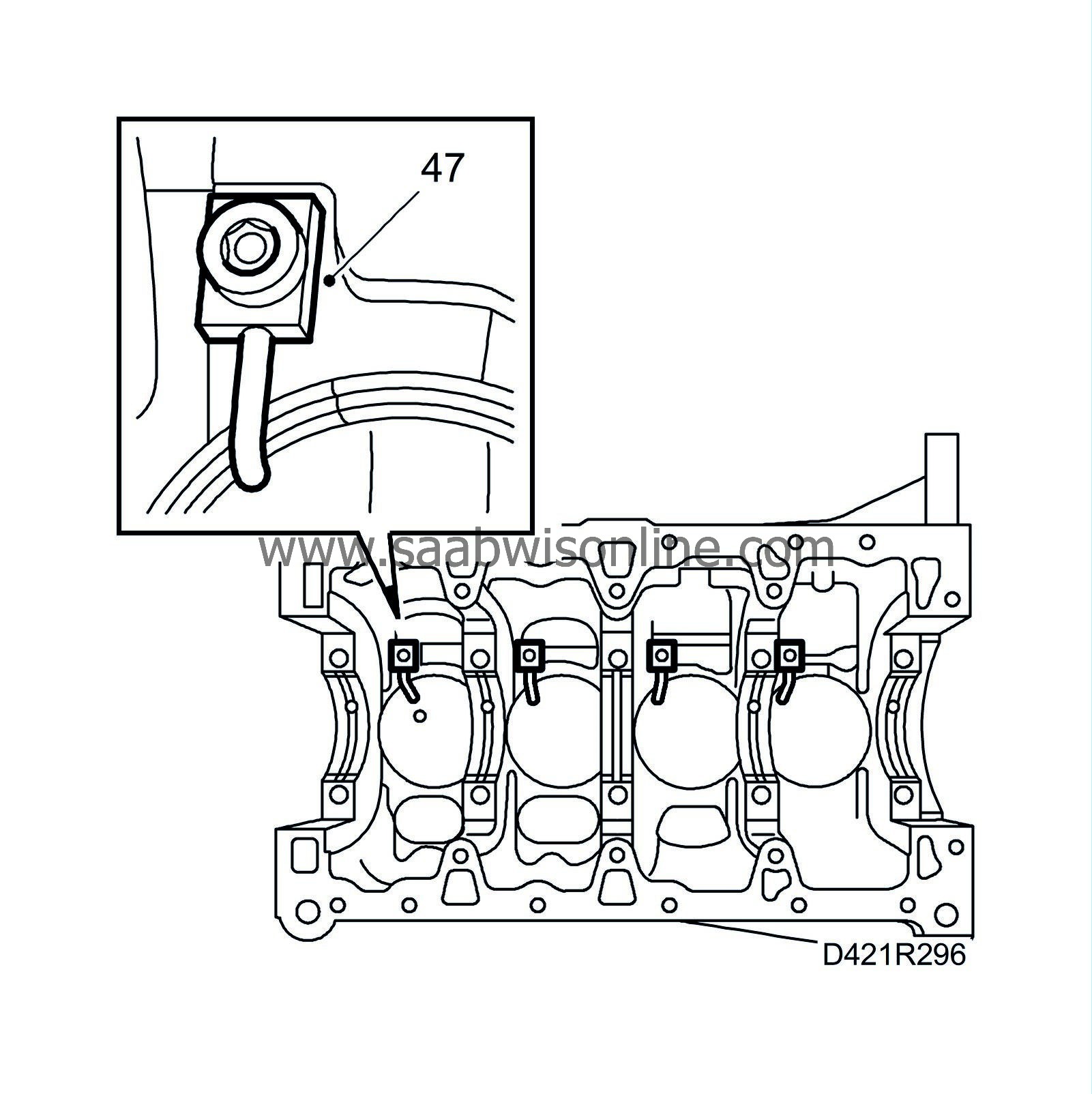
|
|
| To assemble |
| 1. |
Wash all sealing surfaces with benzine, making sure that they are perfectly clean.
|
|
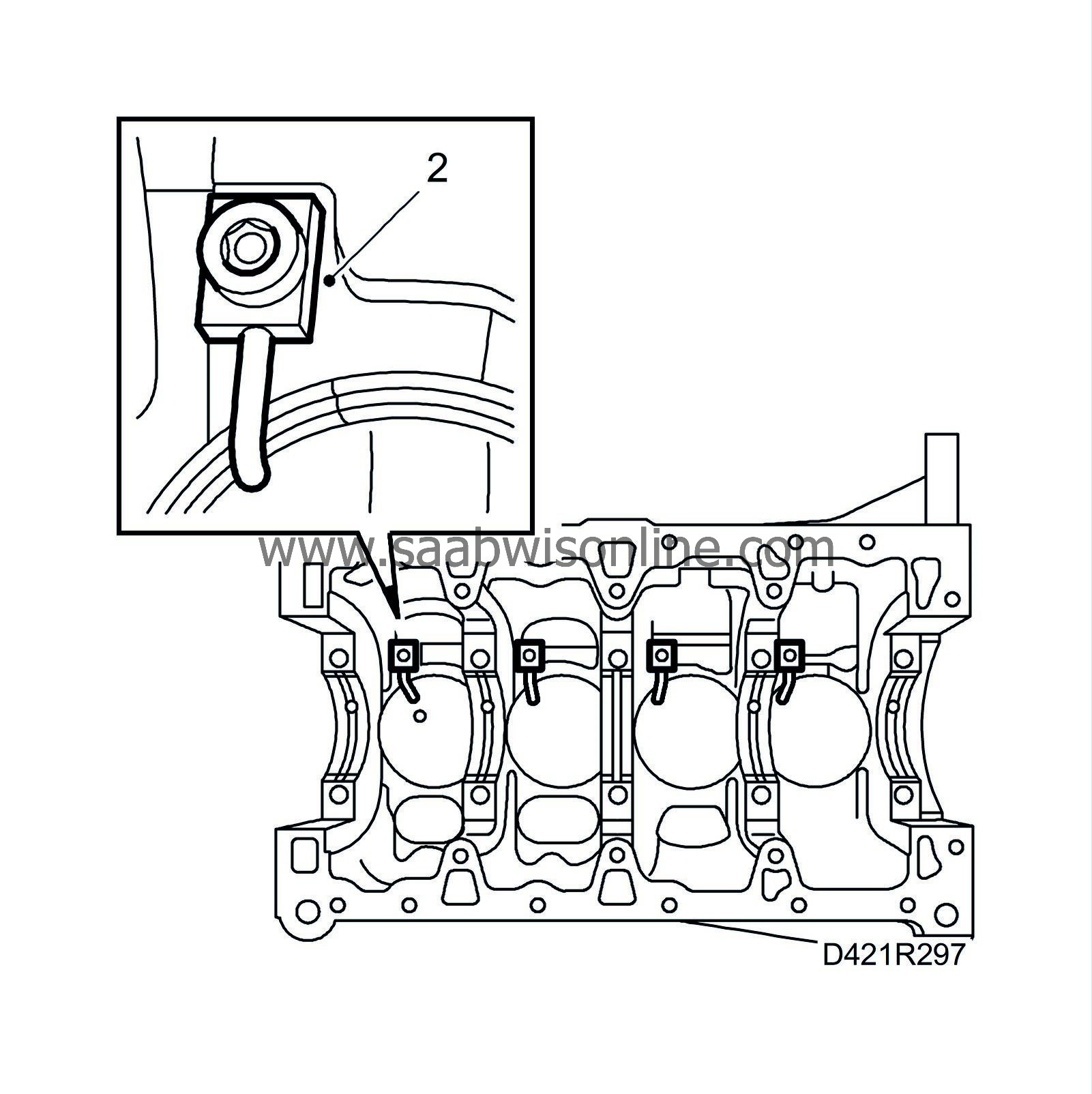
| 2. |
Fit the piston cooling nozzles.
Tightening torque: 22 Nm (16 lbf ft). |
|
| 3. |
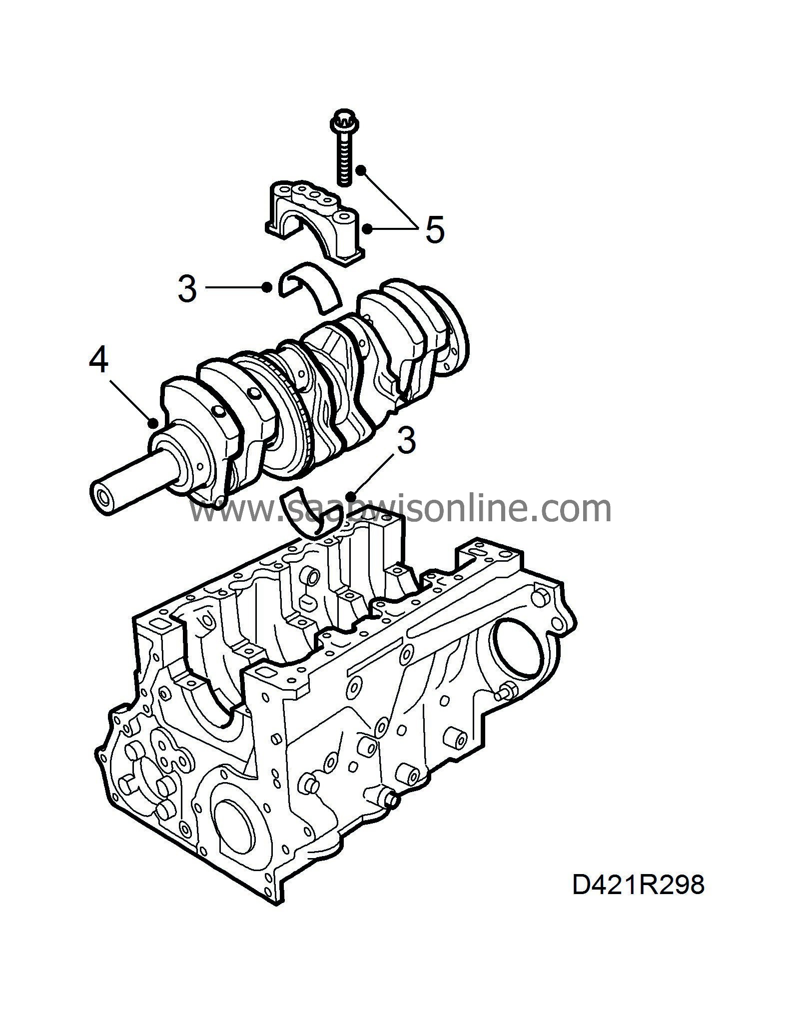
Oil all the main bearings and place them in their relevant positions.
|
|
| 4. |
Put in place the crankshaft.
|
||||||||||
| 5. |
Lubricate and fit all main bearing caps in their correct places, making sure that they are the right way round.
Tightening torque: 90 Nm +60° (66 lbf ft +60°) |
|
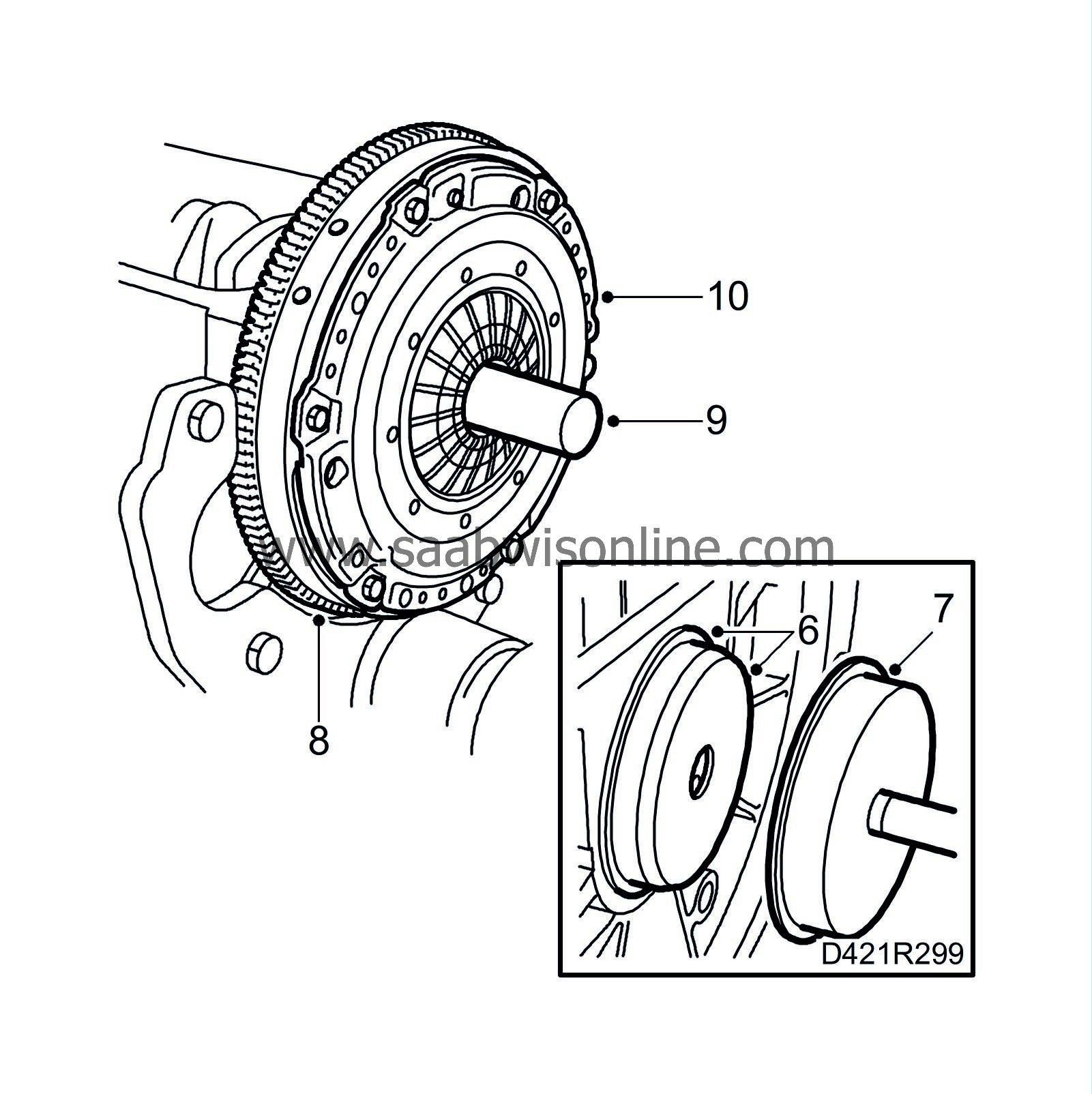
| 6. |
Lubricate the new rear crankshaft seal with non-acidic Vaseline and place it on
83 95 402 Assembly tool, rear crankshaft seal
(KM-934-1).
|
|
| 7. |
Position the seal on the crankshaft with the protective collar and
83 95 402 Assembly tool, rear crankshaft seal
(KM-934-2). Use
83 95 402 Assembly tool, rear crankshaft
(KM-454-4) to press in the seal until it is flush with the cylinder block.
|
|
| 8. |
Fit the flywheel loosely. Use
Thread locking adhesive, Loctite 270
on the bolts. Use
83 94 868 Flywheel locking attachment
and tighten the bolts.
Tightening torque: 45 Nm+30° (33 lbf ft +30°) |
|
| 9. |
Position the
87 92 327 Centre drift, clutch plate
and the clutch plate.
|
|
| 10. |
Fit the pressure plate.
Tightening torque: 22 Nm (16 lbf ft). |
|
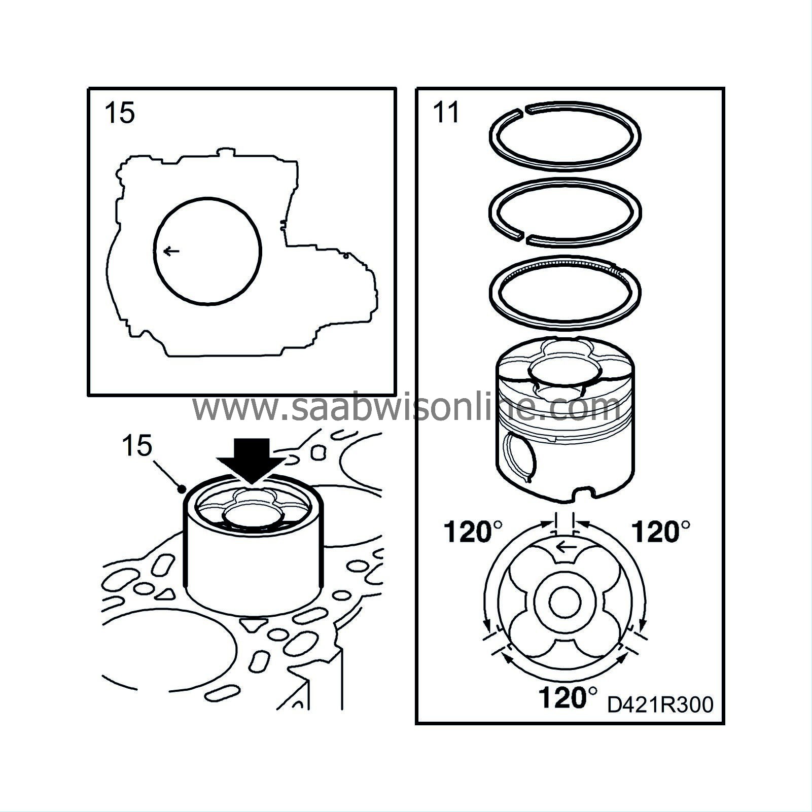
| 11. |
Make sure the piston ring gap is positioned as illustrated.
|
|
| 12. |
Lubricate the piston rings and cylinder with engine oil.
|
|
| 13. |
Screw in the bolts in the connecting rod and press
75 19 531 Protective collar (type 10)
onto the bolt heads to facilitate assembly.
|
|
| 14. |
Turn the crankshaft so that it reaches the top of the stroke in the current cylinder.
|
|
| 15. |
Fit the piston. The arrow on top of the piston must point towards the timing side.
|
|
| 16. |
Lubricate the bearing halves with engine oil and put them in their respective places in the connecting rod and cap.
|
|
| 17. |
Note the position in which the big-end bearing caps are fitted (boss in cap pointing towards flywheel) and fit them with new bolts.
Tightening torque: 35 Nm + 45° (26 lbf ft + 45°) |
||||||||||
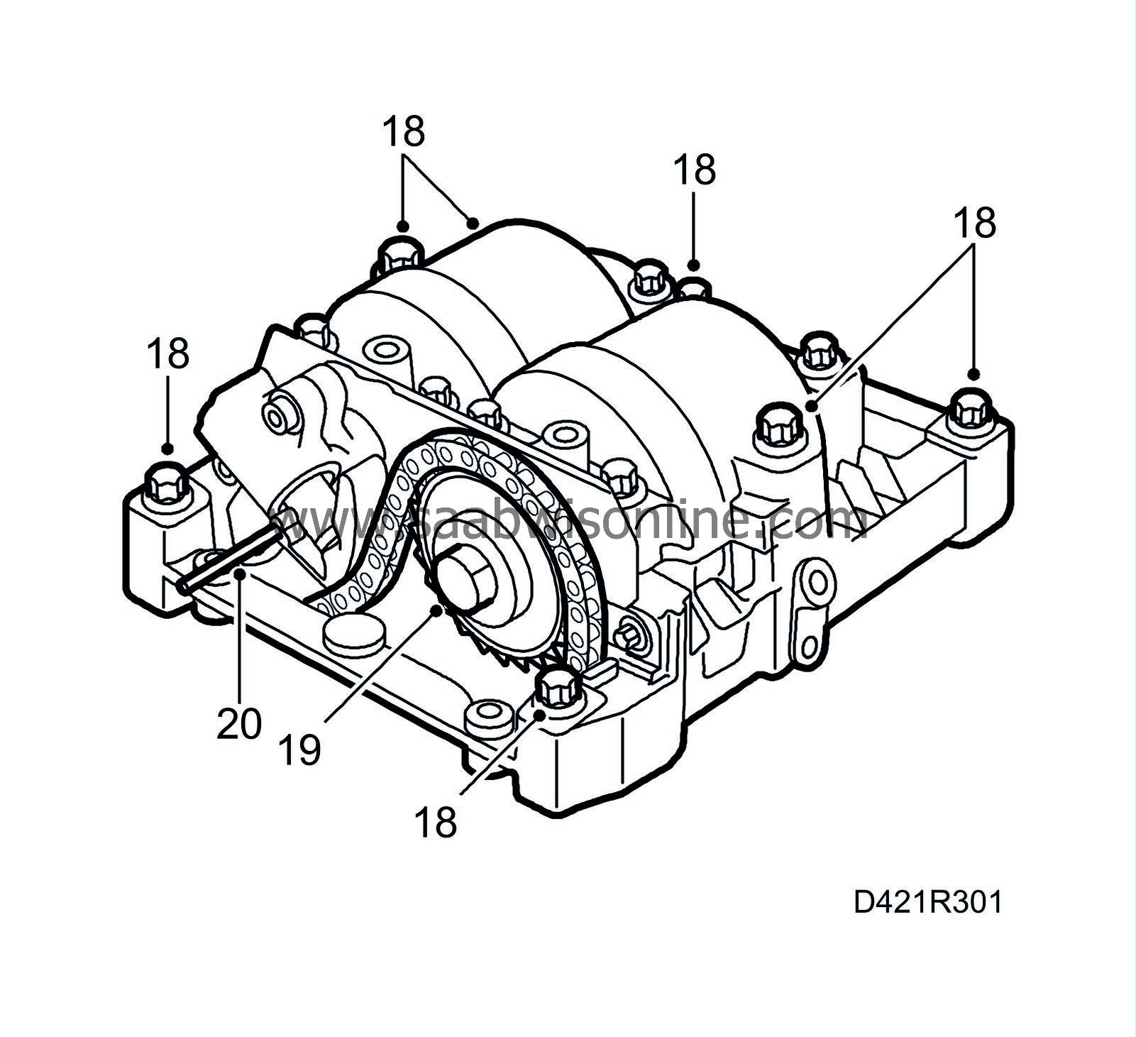
| 18. |
Fit the balancer shaft unit.
Tightening torque: 20 Nm (15 lbf ft). |
|
| 19. |
Position the pulley on the balancer shaft and tighten the bolt.
Tightening torque: 90 Nm + 30°(66 lbf ft + 30°) |
|
| 20. |
Release the chain tensioner.
|
|
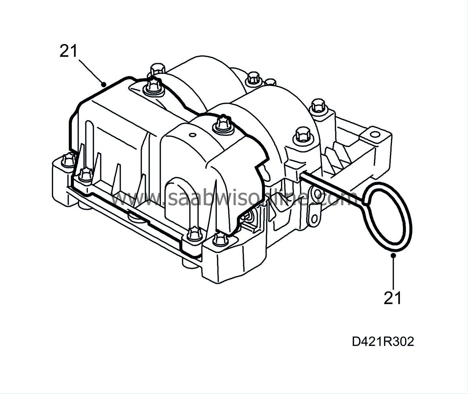
| 21. |
Fit the cover and remove the locking tool from the balancer shafts.
|
|
| 22. |
Fit a new O-ring onto the fuel distribution pump, lubricate the O-ring with non-acidic Vaseline and position the pump to the cylinder block. Fit the bracket to the pump.
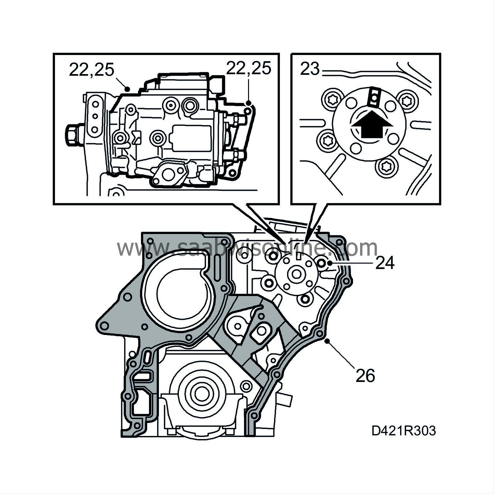
Tightening torque: 20 Nm (15 lbf ft). Position the bolts, fitting them through the hole in the timing cover but not tightening them. |
|
| 23. |
Position
83 95 337 Setting tool, fuel pump
in the fuel distribution pump recess.
|
|
| 24. |
Tighten the bolts for the fuel distribution pump in the timing end of the engine.
Tightening torque: 25 Nm (18 lbf ft). |
|
| 25. |
Tighten the bolts securing the bracket to the cylinder block.
Tightening torque: 20 Nm (15 lbf ft). |
|
| 26. |
Place a new gasket on the cylinder block.
|
|
| 27. |
Remove the inspection gauge from the fuel distribution pump.
|
|
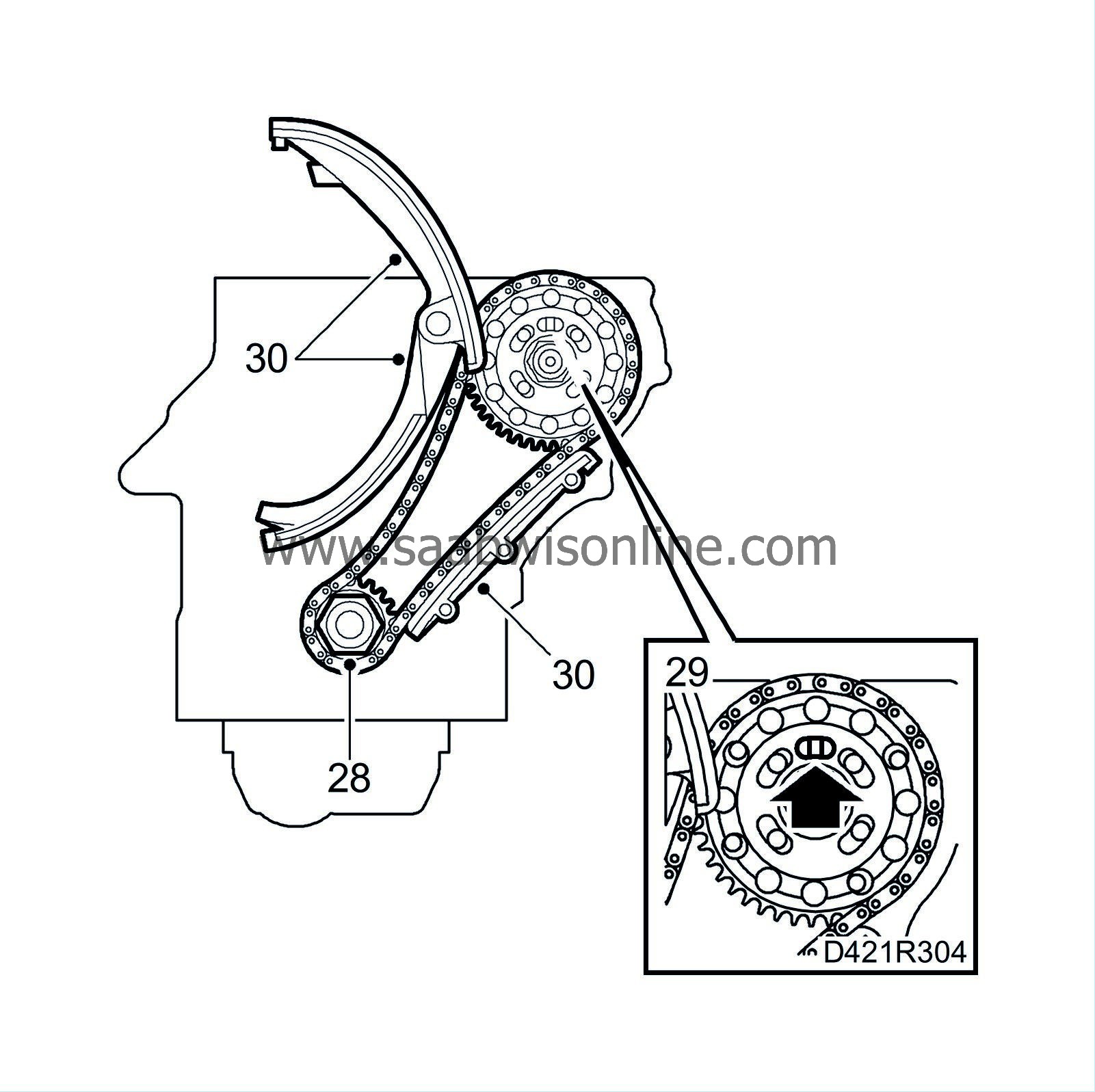
| 28. |
Refit the pulley on the crankshaft and the fuel distribution pump together with the lower timing chain. The lower part of the timing chain must be kept taut.
|
|
| 29. |
Use
83 95 337 Setting tool, fuel pump
to make sure the fuel distribution pump flange is in line with the hole in the pump. Leave the gauge in place.
|
|
| 30. |
Refit all the chain guides.
|
|
| 31. |
Fit the timing cover with bolts in their original positions.
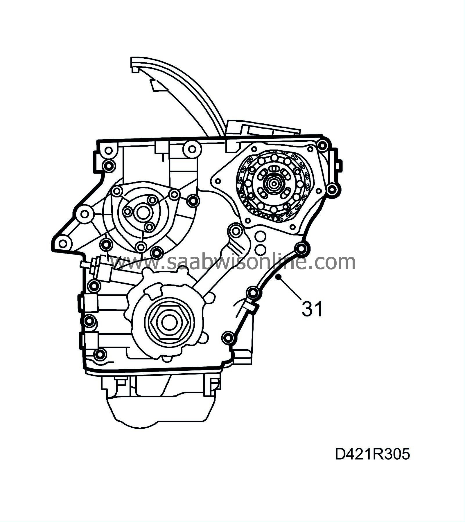
Tightening torque: 20 Nm (15 lbf ft). |
|
| 32. |
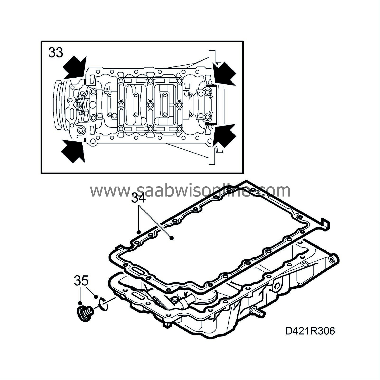
Check that there are no impurities or other foreign matter in the sump and clean the sealing surfaces with benzine.
|
|
| 33. |
Turn the engine and apply
87 81 841 Silicon flange sealant
on the partition joints, see illustration.
|
|
| 34. |
Place a steel rule on the engine sealing surface to the gearbox in order to guide the position of the oil sump and fit it with new gaskets.
Tightening sequence: 1 Tighten all bolts by hand. 2 Torque tighten the bolts to 20 Nm (15 lbf ft). |
|
| 35. |
Refit the oil plug with a new seal.
Tightening torque: 18 Nm (13 lbf ft). |
|
| 36. |
Replace the chain tensioner for the lower timing chain using a new gasket.
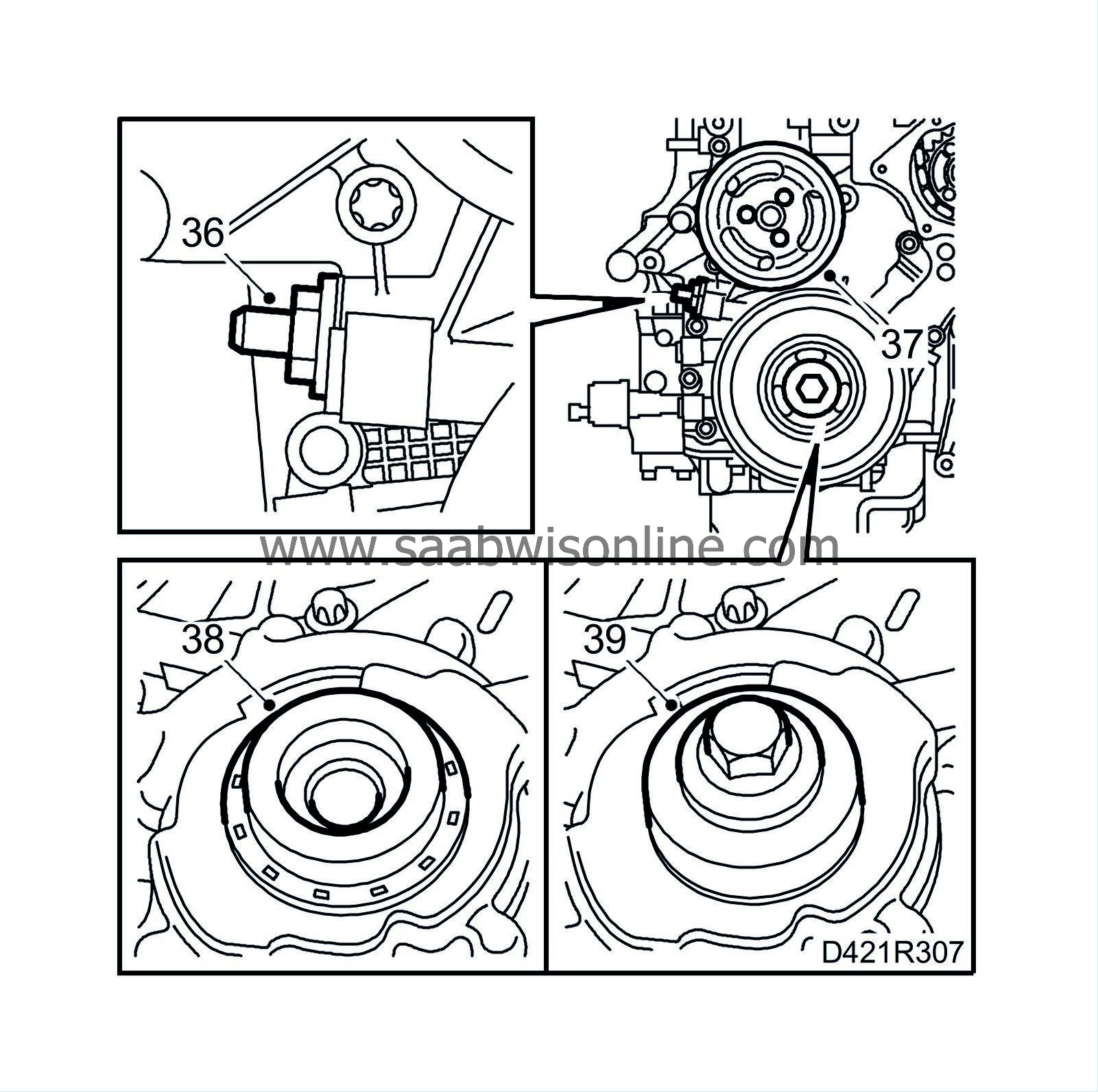
Tightening torque: 60 Nm (44 lbf ft). |
|
| 37. |
Fit the coolant pump pulley.
Tightening torque: 20 Nm (15 lbf ft). |
|
| 38. |
Lubricate the new front crankshaft seal with non-acidic Vaseline and position it on
83 95 410 Assembly tool, front crankshaft seal
(KM-935-1).
|
|
| 39. |
Position the seal with the protective collar and
83 95 410 Assembly tool, front crankshaft seal
(KM-935-2) onto the crankshaft. With the crankshaft pulley bolt, screw in the seal until it is flush with the timing cover.
|
|
| 40. |
Fit the crankshaft pulley with a new bolt. Use
83 95 360 Support, crankshaft pulley
for support.
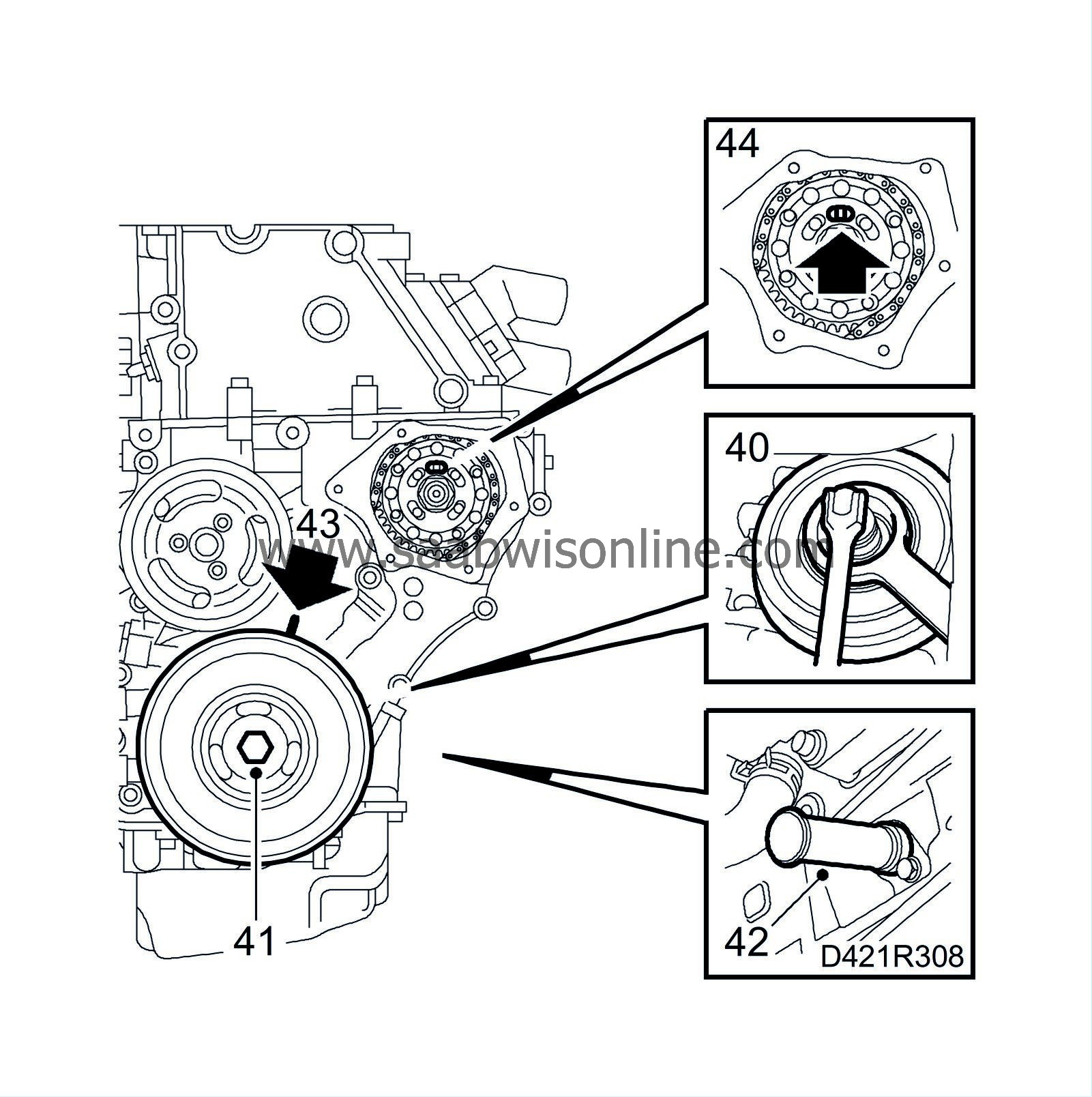
Tightening torque: 150 Nm + 45° (111 lbf ft + 45°) |
|
| 41. |
Turn the crankshaft with the help of the belt pulley's central screw to just before the mark for top dead centre in cylinder 1.
|
|
| 42. |
Insert
83 95 352 Setting tool, crankshaft
into the hole for the crankshaft position sensor. Push the tool somewhat inward at the same time as the crankshaft is turned to the zero point. The tool will then go into a recess in the crankshaft and lock it.
|
|
| 43. |
Make sure the markings on the crankshaft pulley and the timing cover are in line.
|
|
| 44. |
Insert
83 95 337 Installation tool, fuel pump
in the fuel distribution pump recess.
|
|
| 45. |
Use a steel rule to check that the cylinder head and cylinder block are flat and the sealing surfaces are not damaged.
|
|
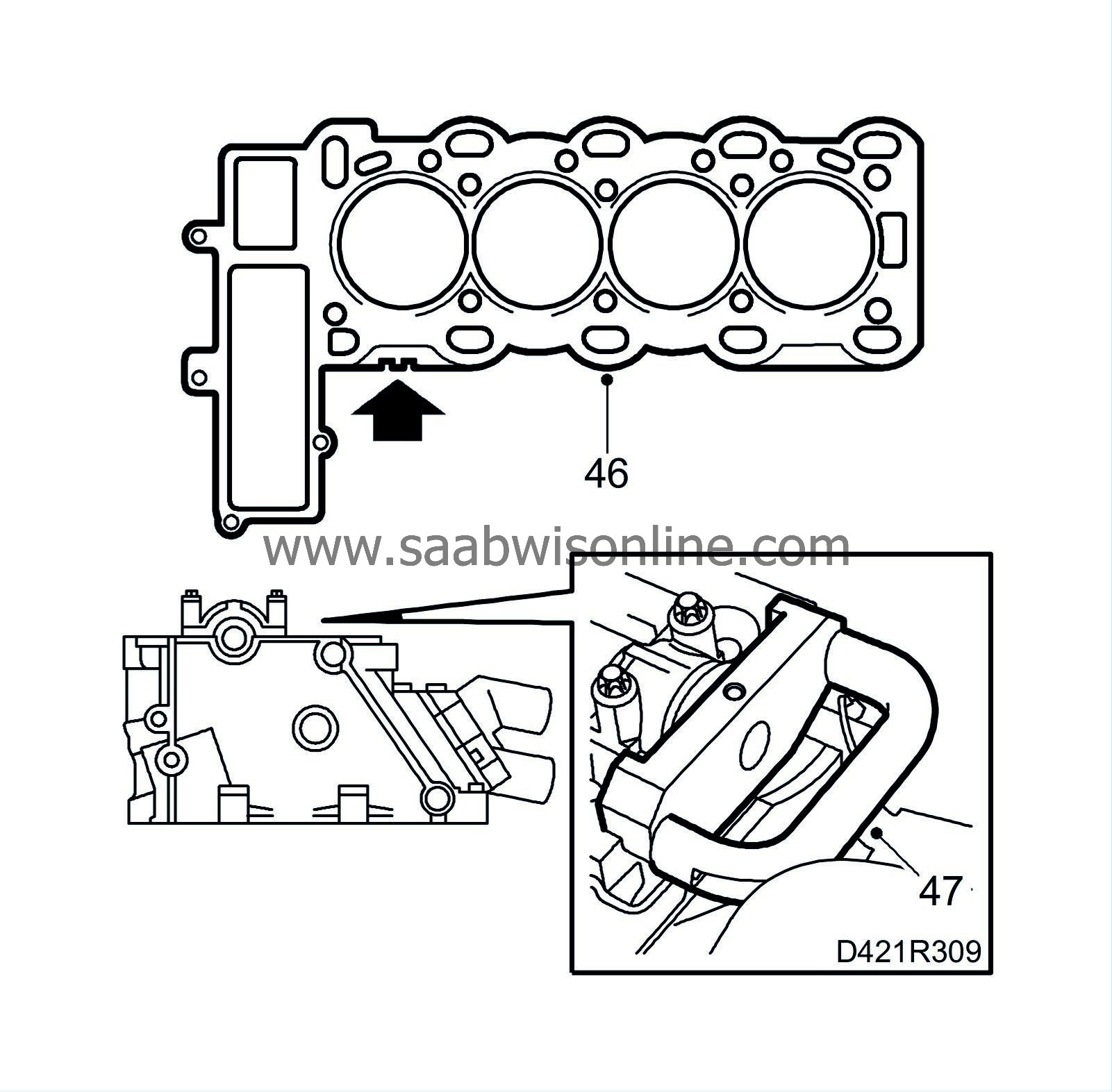
| 46. |
Fit a new gasket on the cylinder head with the same thickness marking as the old one. A gasket with 1 groove (see arrow in illustration) is 1.3mm and a gasket with 2 grooves is 1.4mm.
|
|
| 47. |
Position
83 95 386 Setting tool, camshaft
on the camshaft and cylinder head. The camshaft can be turned somewhat using an open spanner on the hexagonal recess while the gauge is being positioned correctly.
|
|
| 48. |
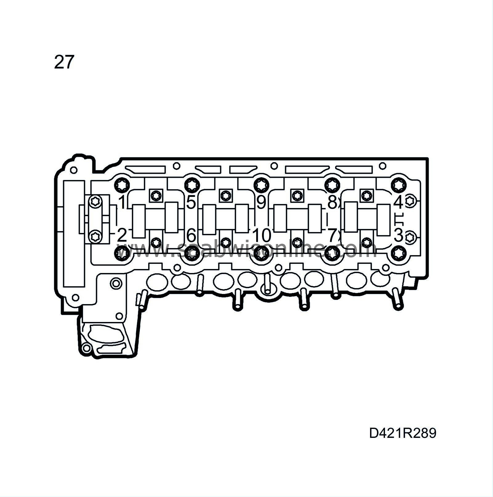
Position the cylinder head on the cylinder block and screw on the cylinder head with new bolts in the illustrated order.
Tightening torques Step I: 25 Nm (18 lbf ft) Step II: 65° Step III: 65° Step IV: 65° Step V: 65° |
||||||||||
| 49. |
Screw in and tighten the bolts in the timing cover as fitted previously.
Tightening torque: 20 Nm (15 lbf ft). |
|
| 50. |
Remove
83 95 337 Setting tool, fuel pump
.
|
|
| 51. |
Position the camshaft sprocket so that it runs easily on the camshaft and fit it with a new bolt. Tighten by hand.
|
||||||||||
| 52. |
Place the upper timing chain with pulley on the fuel pump shaft and secure the pulley on the shaft without tightening the bolts.
|
|
| 53. |
Insert
83 95 337 Installation tool, fuel pump
in the fuel distribution pump recess.
|
|
| 54. |
Remove
83 95 337 Setting tool, fuel pump
and tighten the bolts securing the timing chain pulleys to the fuel distribution pump.
Tightening torque: 20 Nm (15 lbf ft). |
|
| 55. |
Reposition
83 95 337 Setting tool, fuel pump
in the fuel distribution pump recess.
|
|
| 56. |
Fit the adapter for
83 95 394 Setting tool, timing chain
onto the camshaft sprocket and fit the adjusting tool onto the cylinder head.
|
|
| 57. |
Fix the position for the adapter on the camshaft sprocket by lightly twisting it counter-clockwise with a ratchet handle. Tighten the adjustment screw on the tool.
|
||||||||||
| 58. |
Tighten the bolt for the camshaft sprocket using an open spanner for support in the hexagonal recess on the camshaft.
Tightening torque: 90 Nm + 60° (66 lbf ft + 60°) |
|
| 59. |
Replace the chain tensioner for the upper timing chain using a new gasket.
Tightening torque: 60 Nm (44 lbf ft). |
|
| 60. |
Remove all tools and gauges.
|
|
| 61. |
Cover the opening in the timing cover with a lint-free rag clean the sealing surface from any remnants of gasket. Clean the sealing surface on the cover plate as well.
|
|
| 62. |
Apply a bead of
87 81 841 Silicon flange sealant
about 2mm thick on the cover plate, remove the rag from the timing cover and fit the cover plate.
Tightening torque: 6 Nm (5 lbf ft). |
|
| 63. |
Place a new gasket on the camshaft cover. The bolts have sleeves where the gasket is fitted.
|
|
| 64. |
Apply
87 81 841 Silicon flange sealant
on the sealing surface, see illustration.
|
|
| 65. |
Place the camshaft cover on the cylinder head and tighten the screws.
Tightening torque: 8 Nm (6 lbf ft). |
|
| 66. |
Clean the sealing surfaces on the vacuum pump.
|
|
| 67. |
Place a new gasket on the vacuum pump and fit the pump together with the adapter.
Tightening torque: 8 Nm (6 lbf ft). |
||||||||||
| 68. |
Place a new gasket on the cylinder head and fit the lower part of the intake manifold using new nuts.
Tightening torque: 20 Nm (15 lbf ft). |
|
| 69. |
Place a new gasket on the lower part of the intake manifold and fit the upper part.
Tightening torque: 10 Nm (7 lbf ft). |
|
| 70. |
Inspect the tapered fuel rail connections and replace as necessary.
|
|
| 71. |
Connect the fuel rail with clips in their original positions.
Tightening torque: 25 Nm (18 lbf ft). |
|
| 72. |
Check the condition of the fuel return hoses and joints and change as necessary.
|
|
| 73. |
Connect the fuel return hoses to the fuel bridges. Pull off the connection from the fuel pump and connect
30 14 883 Pressure/vacuum pump
. Pump up a vacuum of 750 mbar and wait for 1 minute. Check that the indicator on the tool has not moved.
If a leak is indicated, the fuel bridges must be checked individually. Dismantle the leaking fuel bridge, change the seal and refit the fuel bridge. Check again for any leaks. See |
|
| 74. |
Fit the crankshaft position sensor with a new O-ring.
Tightening torque: 8 Nm (6 lbf ft) |
|
| 75. |
Fit the oil filter housing with a new gasket.
Tightening torque: 20 Nm (15 lbf ft) |
|
| 76. |
Fit a new oil filter and tighten the oil filter housing cover.
Tightening torque: 25 Nm (19 lbf ft). |
|||||||
| 77. |
Fit the thermostat housing.
Tightening torque: 8 Nm (6 lbf ft). |
|
| 78. |
Connect the hose to the thermostat housing.
|
|
| 79. |
Fit the generator bracket.
Tightening torque: 20 Nm (15 lbf ft) |
|
| 80. |
Fit the engine oil pressure sensor.
Tightening torque: 30 Nm (22 lbf ft). |
|
| 81. |
Fit the exhaust manifold with turbocharger.
Tightening torque: 22 Nm (16 lbf ft) |
|
| 82. |
Fit the connections for both turbocharger oil pipes to the cylinder block.
|
|
| 83. |
Connect the turbocharger oil return pipe to the cylinder block.
Tightening torque: 30 Nm (22 lbf ft). |
|
| 84. |
Connect the turbocharger oil delivery pipe to the cylinder block.
Tightening torque: 20 Nm (15 lbf ft) |
|
| 85. |
Move back the exhaust manifold stay and tighten the bolts.
Tightening torque: 25 Nm (18 lbf ft) |
|
| 86. |
Fit the power steering pump with bracket.
|
|
| 87. |
Fit the dipstick.
|
|
| 88. |
Fit the engine mounting bracket to the timing cover.
Tightening torque: 47 Nm (35 lbf ft) |
|
| 89. |
Fit the generator.
Tightening torque: 35 Nm (26 lbf ft) |
|
| 90. |
Fit the belt tensioner and tighten the upper bolt first.
Tightening torque: 42 Nm (31 lbf ft). Tighten the lower bolt. Tightening torque: 23 Nm (17 lbf ft). |
|
| 91. |
Connect the fuel lines to the fuel distribution pump with new seals.
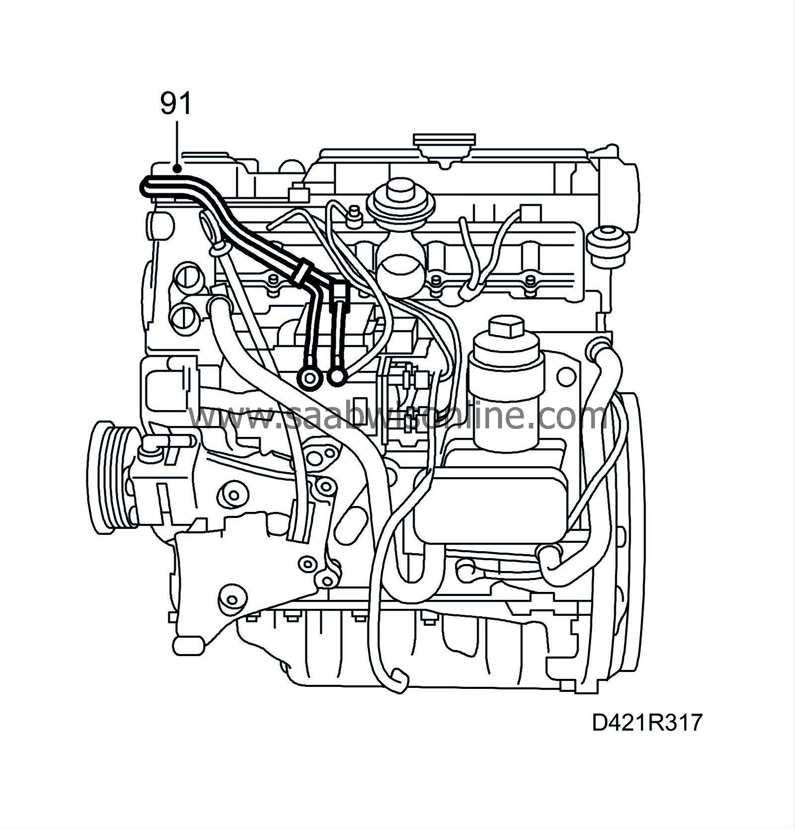
Tightening torque: 25 Nm (18 lbf ft) |
|
| 92. |
Hook on
83 92 409 Lifting sling
and lift the engine from the work stand. Remove the holder.
|
|

