Valve gear
| Valve gear |
| To remove |
| Important | ||
|
The cylindrical surfaces surrounding the valve springs are sealing surfaces for the tappets. These surfaces must not be scored or scratched. Protect the tappet guides with protective collar 83 93 746. |
||
| 1. |
Place the removed
Cylinder head
in such a way that the fuel injector nozzles, glow plugs or valves are not damaged.
|
|
| 2. |
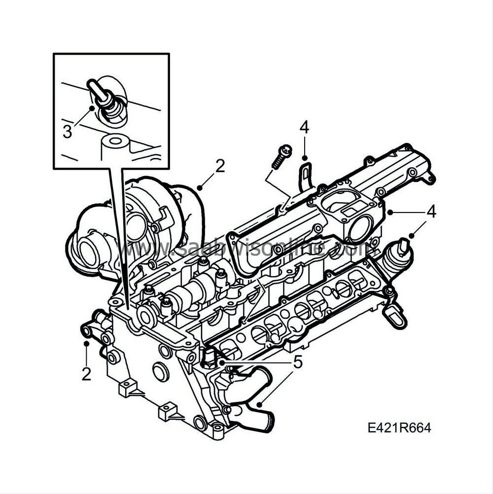
Remove the exhaust manifold with turbocharger and the generator bracket.
|
|
| 3. |
Remove the glow plugs.
|
|
| 4. |
Remove the upper part of the intake manifold, lifting eye bolt and the lower part of the intake manifold.
|
|
| 5. |
Remove the thermostat housing and the coolant temperature sensor.
|
|
| 6. |
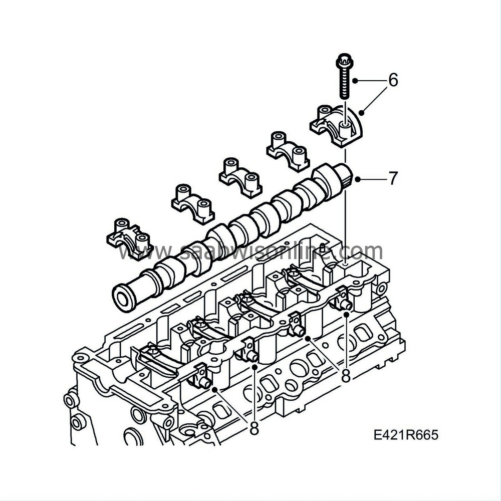
Undo the camshaft bearing caps in steps of 0.5-1 revolution as illustrated starting at cap number 1.
|
||||||||||
| 7. |
Lift off the camshaft bearing caps and remove the camshaft.
|
||||||||||
| 8. |
Remove the fuel bridge retaining bolts and pull the fuel bridges from the cylinder head.
|
|
| 9. |
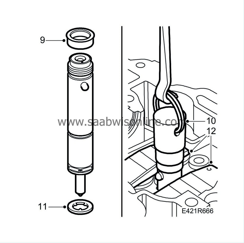
Remove the seals from the injector connections in the fuel bridges.
|
|
| 10. |
Fit
83 95 378 Dismantling tool, injectors
onto the injectors. Fit
87 91 360 Puller
onto the adapter and pull out the injectors.
|
|
| 11. |
Remove the seals from the injectors.
|
|
| 12. |
Remove the valve bridges.
|
||||||||||
| 13. |
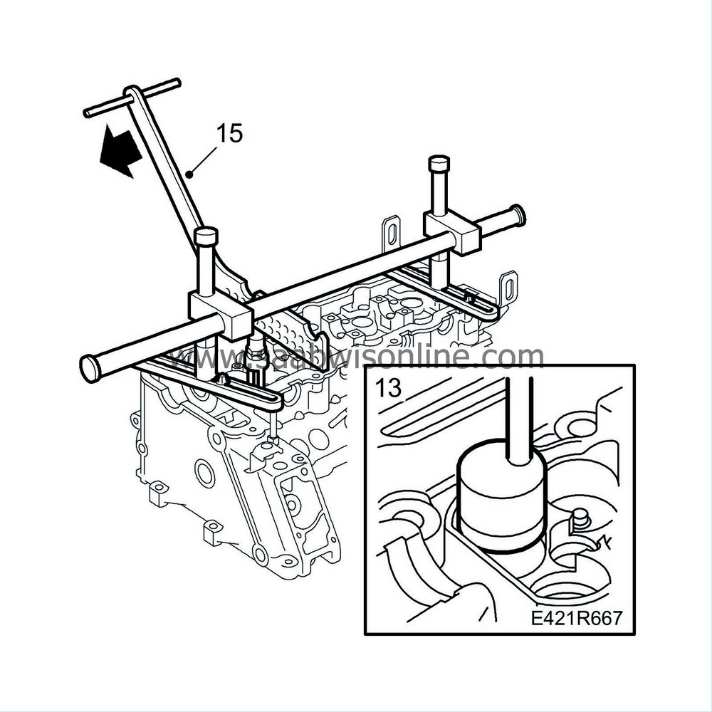
Lift up the tappets with
83 91 401 Magnetic tool
and fit
83 95 022 Protective collar.
|
|
| 14. |
Mark the valves so they can be refitted in the same place.
|
|
| 15. |
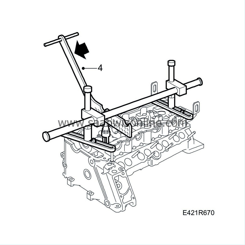
Fit
83 95 246 Valve spring compressor
onto the cylinder head. Press down the lever and remove the valve cones.
|
|
| 16. |
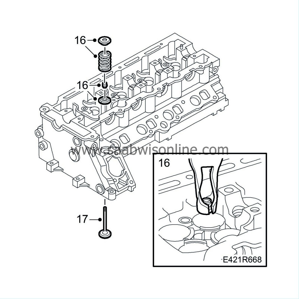
Lift out the spring disc and the valve spring. Remove the valve guide seal with
83 94 157 Pliers, valve guide seal
and lift up the lower spring disc.
|
|
| 17. |
Remove the valves and place them in
83 93 787 Valve stand
.
|
|
| To fit |
| Important | ||
|
Defective valve-stem seals must be changed and the sealing surfaces and bearings oiled before mounting the valves. Make sure the cylinder head is supported so that the valves are not bent when the camshaft is tightened. |
||
| 1. |
Clean all parts and inspect sealing surfaces, sliding surfaces and bearing surfaces for wear.
|
|
| 2. |
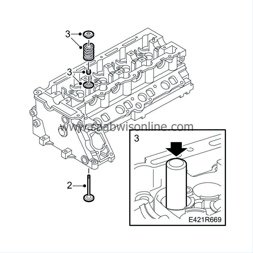
Lubricate the valves with engine oil and fit them in their respective positions according to the marks made earlier.
|
|
| 3. |
Put in place the lower spring disc, lubricate the valve-stem seals with engine oil and fit them using
83 95 071 Assembly tool, valve-stem seal
. Fit the spring and spring disc and place the valve cones in the groove in the valve disc.
|
|
| 4. |
Press down the lever on the valve spring compressor and position the valve cones.
|
|
| 5. |
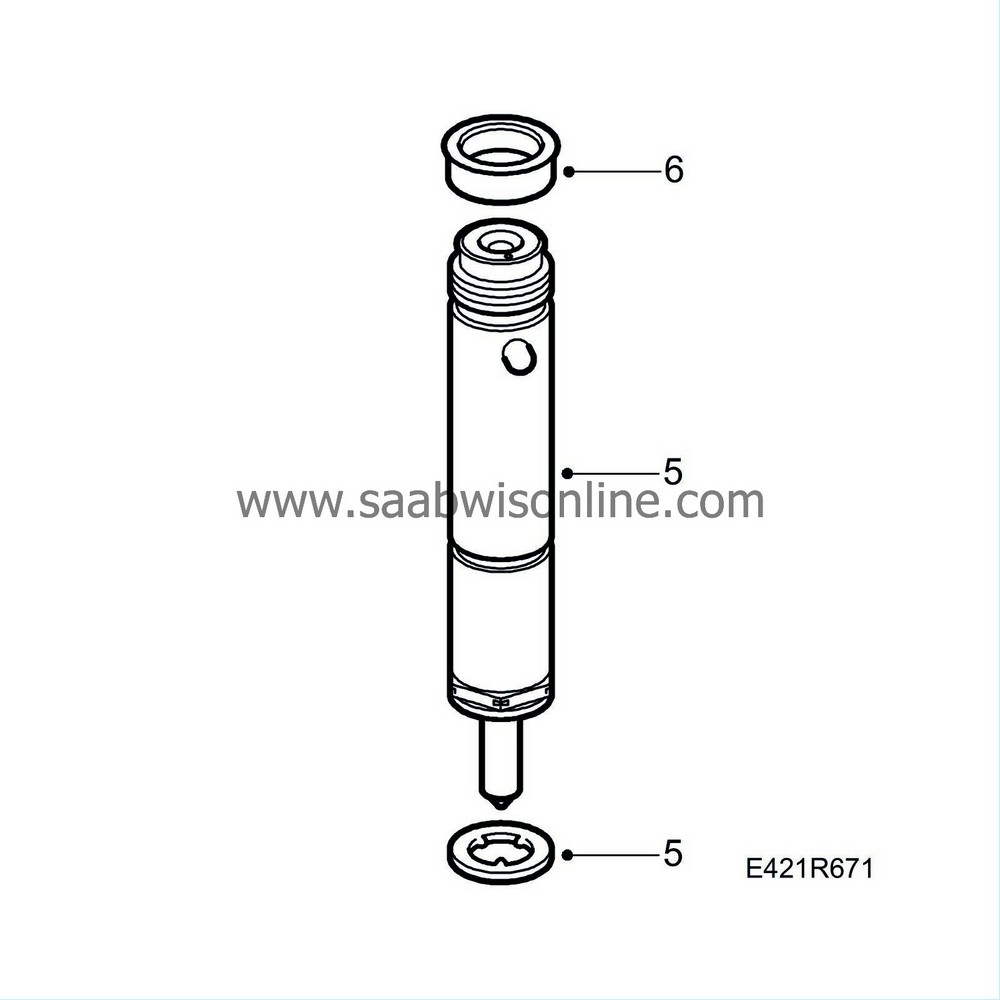
Fit the new seals onto the injectors and fit them.
|
|
| 6. |
Fit the new seals onto the injector connections to the fuel bridges. Remove and remnants from old seals.
|
|
| 7. |
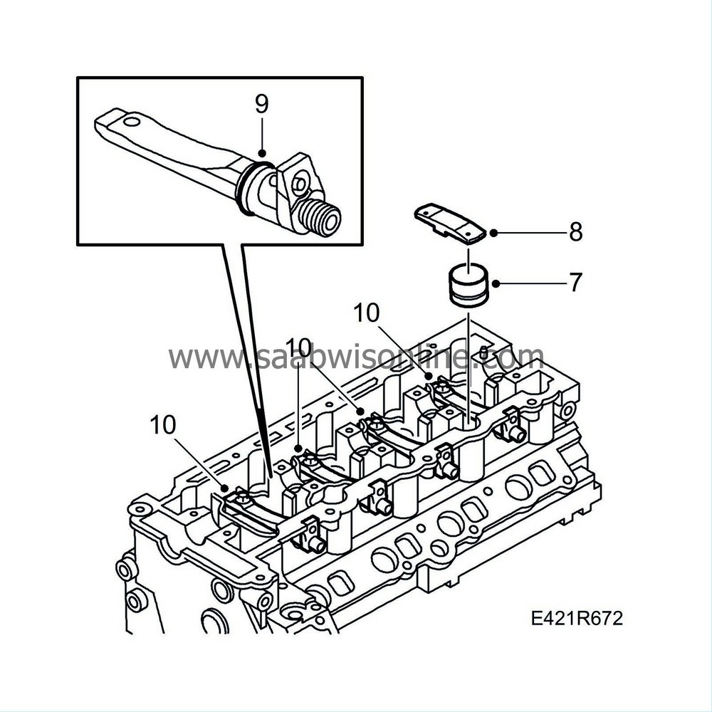
Remove the protective collars, lubricate the tappets with engine oil and position them in the cylinder head.
|
|
| 8. |
Fit the valve bridges.
|
||||||||||
| 9. |
Fit the new O-rings onto the fuel bridges and carefully push them into the cylinder head.
|
|
| 10. |
Tighten the fuel bridge bolts.
Tightening torque: 5 Nm + 360° (4 lbf ft + 360°) |
|
| 11. |
Lubricate the camshaft and valve bridge sliding surfaces.
|
|
| 12. |
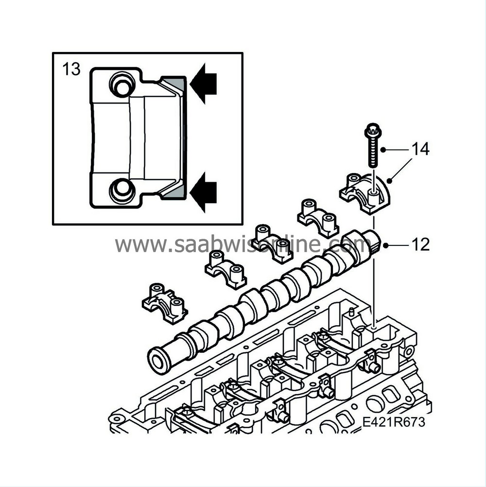
Position the camshaft and place the camshaft bearing caps in their respective positions.
|
|
| 13. |
Apply
87 81 841 Silicon flange seal
to the camshaft bearing cap sealing surfaces, see illustration.
|
|
| 14. |
Tighten the camshaft bearing caps in steps of 0.5-1 revolution as illustrated starting at cap number 3.
Tightening torque: 20 Nm (15 lbf ft) |
|
| 15. |
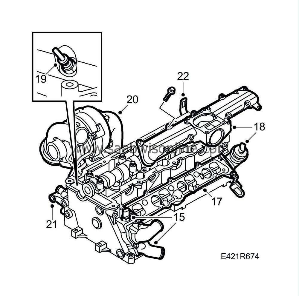
Fit the coolant temperature sensor and replace the thermostat housing with a new gasket.
|
|
| 16. |
Clean away gasket remnants from the sealing surfaces on the cylinder head and intake manifold.
|
|
| 17. |
Place a new gasket on the cylinder head and fit the lower part of the intake manifold using new bolts.
Tightening torque: 20 Nm (15 lbf ft) |
|
| 18. |
Clean the sealing surfaces, place a new gasket on the lower part of the intake manifold and fit the upper part of the intake manifold.
Tightening torque: 10 Nm (7 lbf ft) |
|
| 19. |
Fit the glow plugs.
Tightening torque: 10 Nm (7 lbf ft) |
|
| 20. |
Clean the sealing surfaces and fit the exhaust manifold to the cylinder head with a new gasket and new nuts.
Tightening torque: 22 Nm (16 lbf ft) |
|
| 21. |
Refit the generator bracket with a new gasket.
Tightening torque: 20 Nm (15 lbf ft) |
|
| 22. |
Fit the lifting eye bolts.
|
|
| 23. |
Fit the
Cylinder head.
|
|


