Cylinder head
| Cylinder head |
| Removal of cylinder head (in situ) |
| 2. |
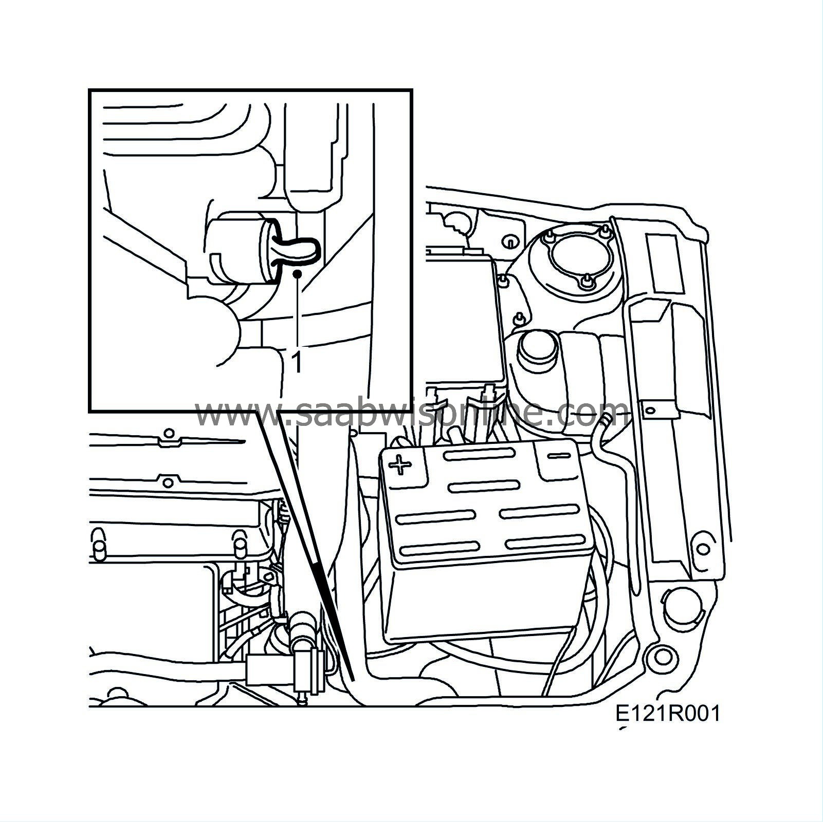
Lower the car slightly and remove the front right wheel and disconnect the steering servo pipe from the subframe.

|
|
| 3. |
Drive in a
83 95 238 Wedge
between the oil sump and subframe on the right-hand side.
|
|
| 4. |
Remove the right-hand engine mounting with yoke and the bracket for the servo pump pipe.
|
|
| 5. |
Remove the mass air flow sensor with rubber gaiter. Unplug the connectors for the mass air flow sensor and turbo wastegate.
|
|
| 6. |
Remove the crankcase breather pipe.
|
|
| 7. |
Remove the front lifting eye from the engine and pull it out of the rubber.
|
|
| 8. |
Remove the charge air pipe, bypass valve and pressure/temperature sensor connector. Disconnect the bypass valve vacuum hose. Plug the throttle body and the hose by the charge air cooler.

|
|
| 9. |
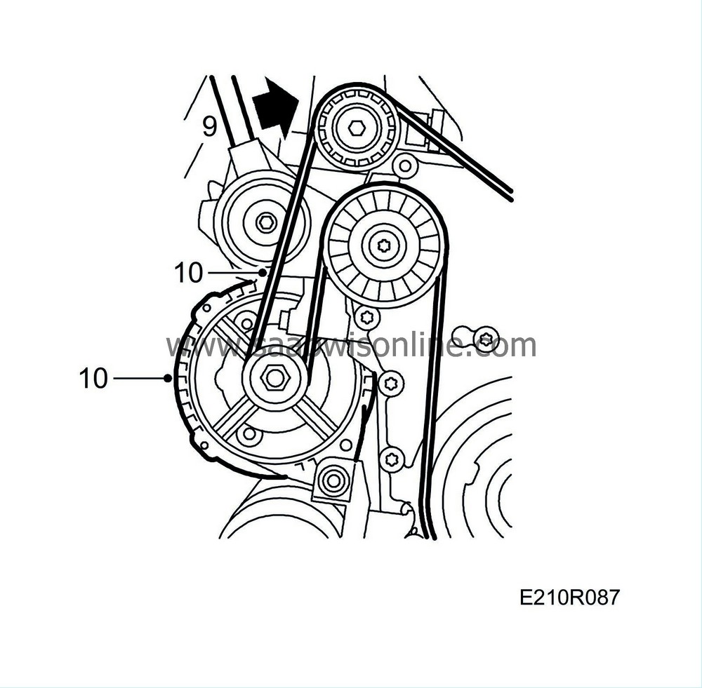
Release the tension of the belt tensioner using
83 95 254 Drawbar handle, hydraulic belt tensioner
and insert a 3.5 mm allen key into the hole. Remove the poly-V-belt.
|
||||||||||
| 10. |
Remove the belt tensioner, detach and move aside the generator. Remove the generator bracket.
|
|
| 11. |
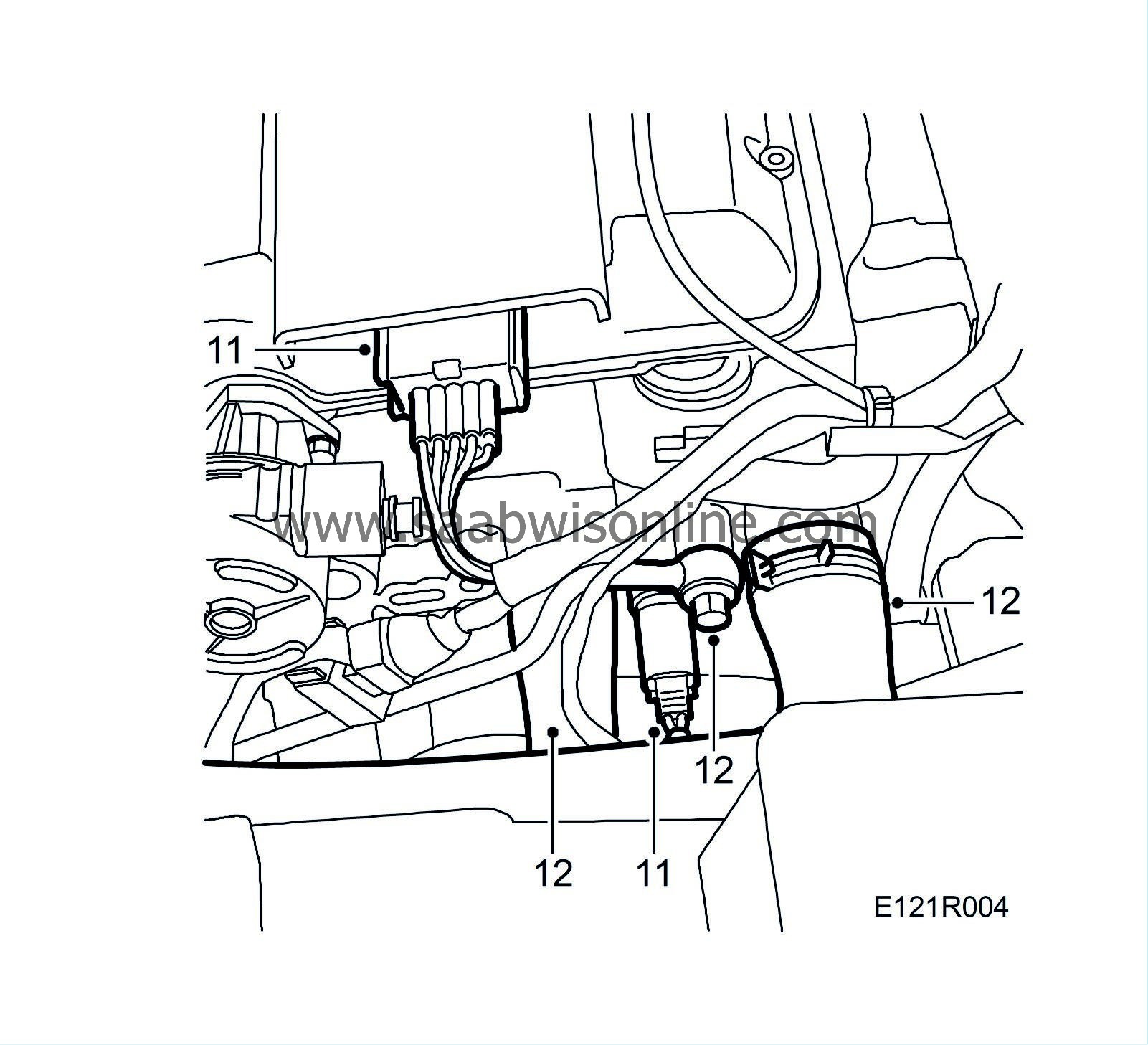
Unplug the temperature sensor and ignition discharge module connectors.
|
|
| 12. |
Remove the coolant hoses from the cylinder head.
|
|
| 13. |
Remove the cover from the throttle body lever. Detach the accelerator cable, remove the dipstick with pipe and detach the fuel hoses using
83 95 261 Tool, fuel hose
.

|
|
| 14. |
Remove the crankcase breather nipple from the timing cover.
|
|
| 15. |
Raise the car and remove the intake manifold steady bar.

|
|
| 16. |
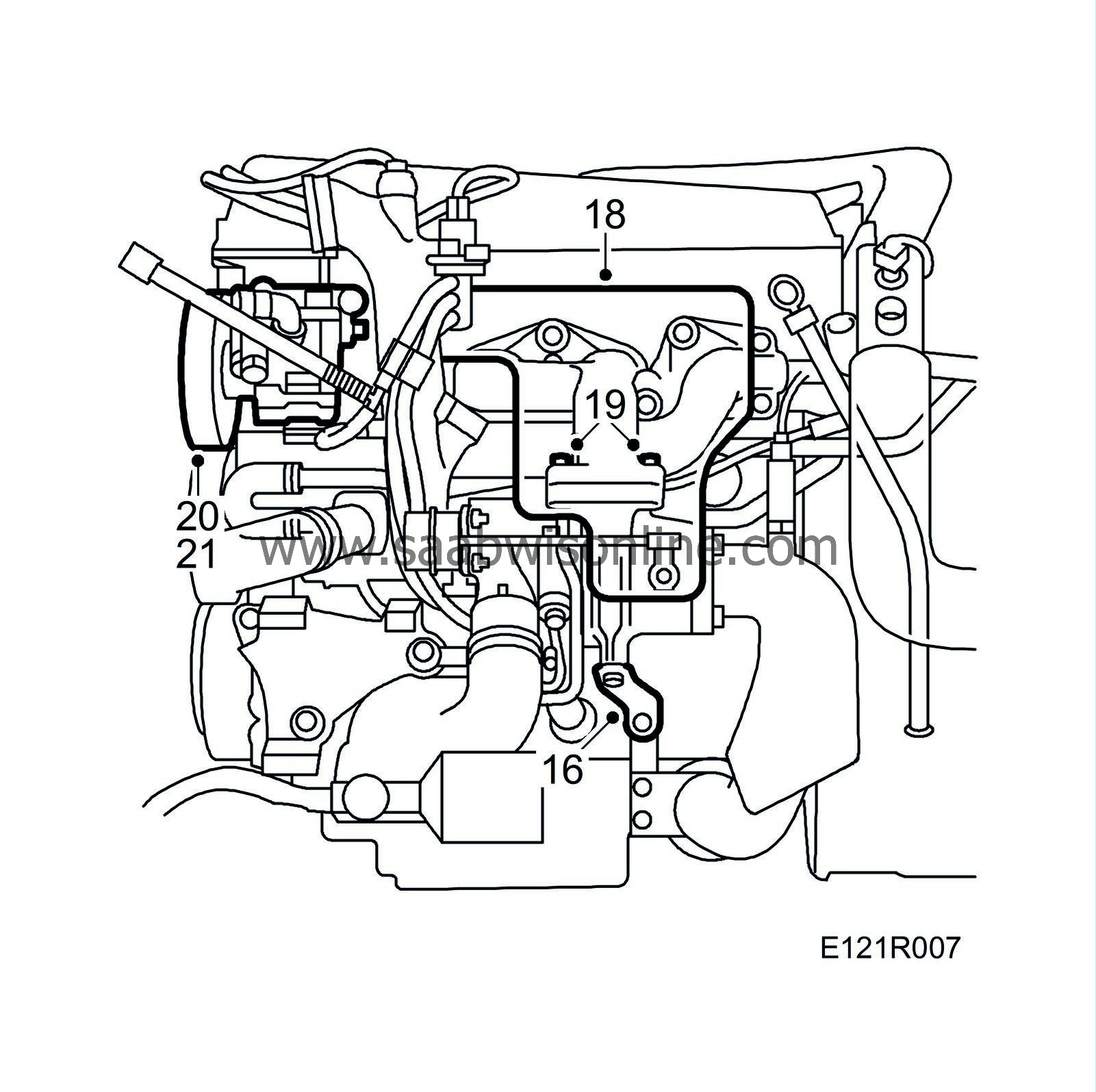
Remove the turbocharger steady bar.
|
|
| 17. |
Lower the car to the floor.
|
|
| 18. |
Remove the heat shield from the turbocharger and exhaust manifold.
|
|
| 19. |
Remove the four retaining nuts between the exhaust manifold and the turbocharger. Heat the nuts carefully if they are stuck.
|
|
| 20. |
Remove the servo pump and suspend it from the radiator crossmember.
|
|
| 21. |
Remove the lower screw from the steering servo pump bracket.
|
|
| 22. |
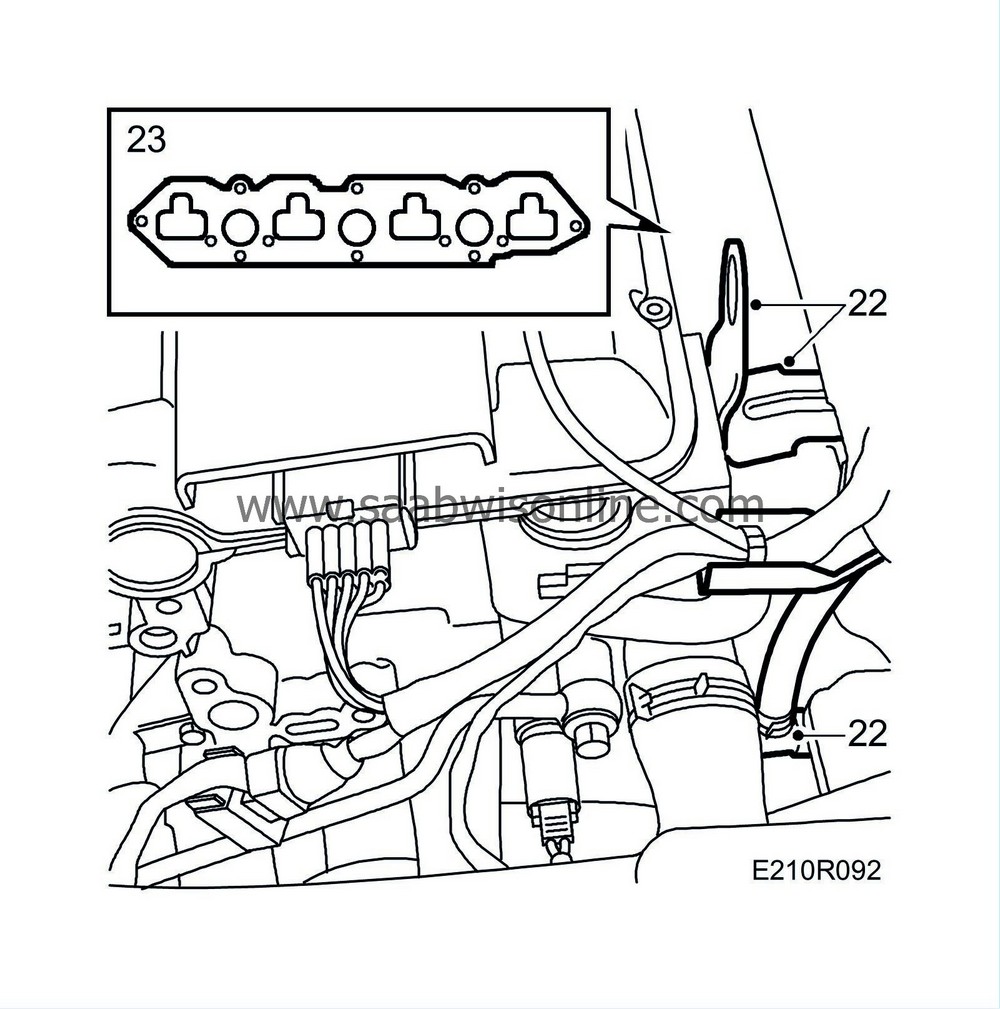
Remove the bracket for the ignition discharge module connectors from the rear lifting eye and the bracket for the heat exchanger pipe.
|
|
| 23. |
Remove the intake manifold with partition. Move the manifold rearwards towards the bulkhead. The centre retaining bolts may be more easily accessible from underneath. Leave the intake manifold in the car.
|
|
| 24. |
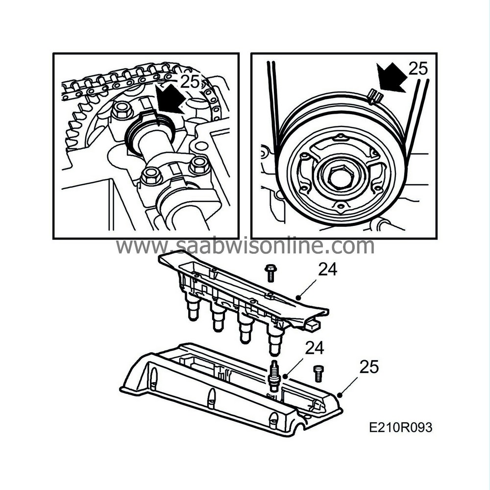
Remove the ignition discharge module and spark plugs.
|
|
| 25. |
Remove the camshaft cover, line up the crankshaft pulley mark with the timing cover and check that the camshafts are in line with their timing marks.
|
|
| 26. |
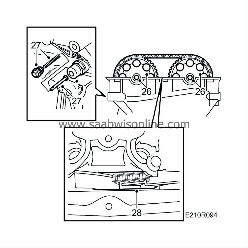
Undo the camshaft sprocket bolts. Hold the end of the camshaft with an open-ended spanner to prevent it from turning.
|
|
| 27. |
Undo the bolt on the idler sprocket and remove the chain tensioner. Use a 27 mm socket after removing the plug with spring and pushrod.
|
|
| 28. |
Remove the camshaft sprockets and fit a rubber band between the chain guides.
|
|
| 29. |
Remove the cylinder head. Start with the bolts in the timing cover. Proceed in reverse order to fitting. Use a pair of pliers or a magnet to retrieve the bolts.

|
|
| 30. |
Wipe up any oil that has run out. Make sure that the timing chain does not obstruct its removal and then lift off the cylinder head.
|
|
| Fitting of cylinder head (in car) |
| 1. |
Fit the inner gasket for the camshaft cover partition with
46 20 084 Ultra fast adhesive
.

|
|
| 2. |
Position the gasket between the intake manifold and intermediate partition by means of two straps.
|
|
| 3. |
Carefully clean all sealing surfaces. Apply a 2 mm thick and 10-20 mm long bead of
93 21 795 Flange sealant
to the inner part of the upper contact surface of the timing cover (against the cylinder head). Turn the engine in the stand, turning the crankshaft 45° to lower the pistons.
Fit a rubber band round the chain guides and mount the cylinder head with a new gasket. Check that it is correctly seated on the locating sockets and that the chain is not trapped. |
|
| 4. |
Fit the cylinder head Torx bolts and tighten to torque
Tightening torque in three stages - Step I: 40 Nm (30 lbf ft) - Step II: 60 Nm (44 lbf ft) - Step III: Tighten a further 90° Tightening sequence for the cylinder head bolts as shown. |
|
| 5. |
Fit the two bolts between the timing cover and cylinder head.
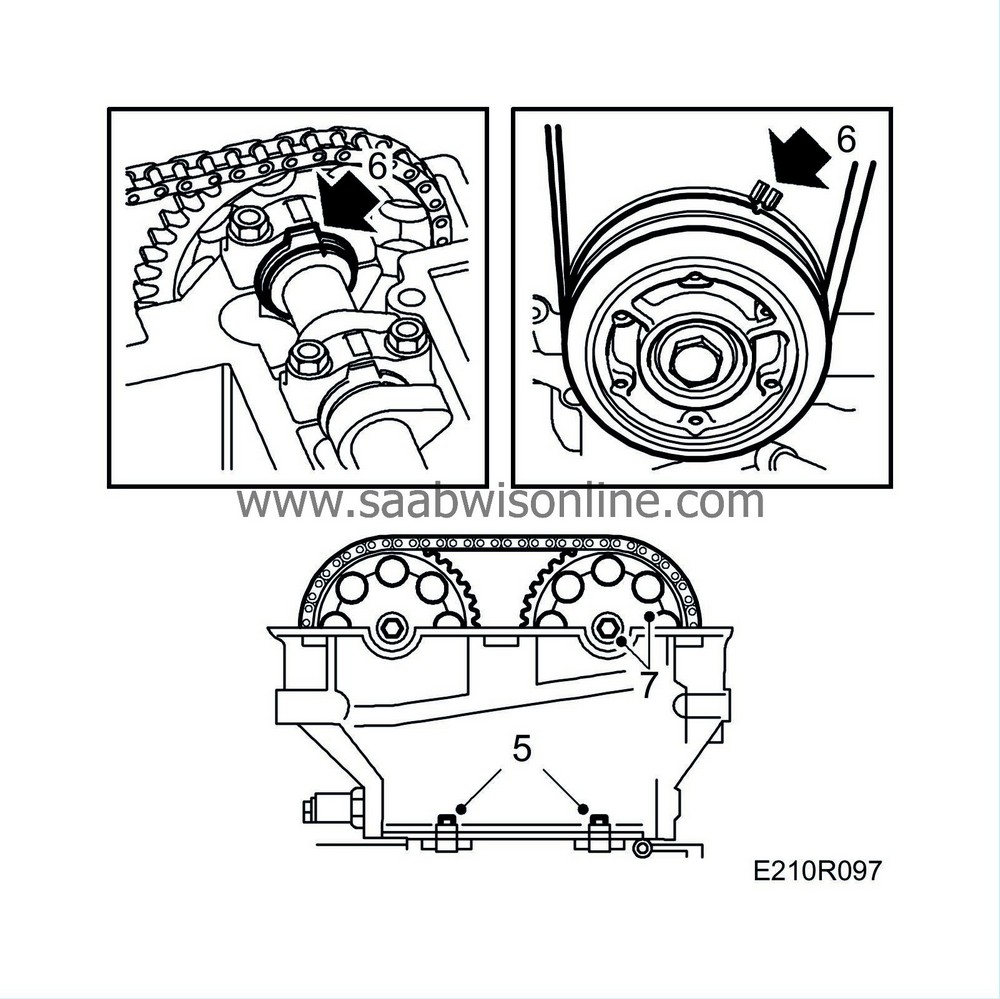
Tightening torque: 22 Nm (16 lbf ft) |
|
| 6. |
Check that the camshafts are in line with their timing marks and reset the crankshaft in line with the 0 mark.
|
|
| 7. |
Fit the camshaft sprockets and chain. Start with the camshaft on the exhaust side.
Do not tighten the bolts yet!
|
|
| 8. |
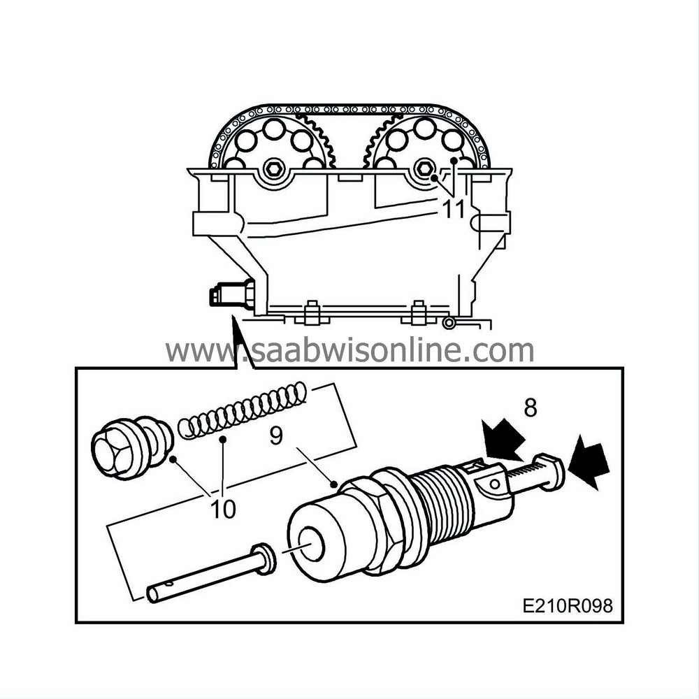
Prepare the chain tensioner for fitting by pressing down the catch and pushing in the chain tensioner.
|
|
| 9. |
Fit the chain tensioner, using a 27 mm socket.
Tightening torque 63 Nm (47 lbf ft) |
|
| 10. |
Fit the chain tensioner plug with push rod and spring.
Tightening torque: 22 Nm (16 lbf ft) |
|
| 11. |
Tighten the bolt on the idler pulley. Tighten the camshaft sprocket bolts. Hold the end of the camshaft with a spanner.
Tightening torque 63 Nm (47 lbf ft) |
|
| 12. |
Check that the chain is correctly seated in the guides. Rotate the crankshaft two complete turns and check the settings of the crankshaft pulley and camshafts.
|
|
| 13. |
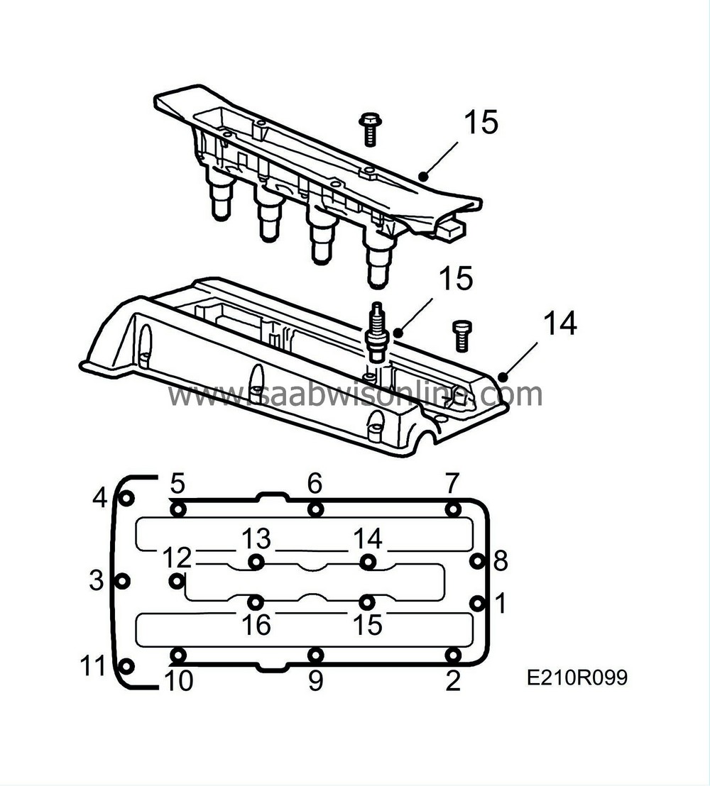
Clean the sealing surface of the camshaft cover with benzene.
|
|
| 14. |
Coat the opening in the camshaft cover thinly with oil and fit the cover, starting at the opening. Make sure that the cables at the edge of the cover against the intake manifold do not get trapped. Then tighten the bolt located furthest to the front at the timing chain end. After that, continue all the way round on both the inside and outside.
Tightening torque 15 Nm (11 lbf ft) |
|
| 15. |
Fit the spark plugs.
Tightening torque: 28 Nm (21 lbf ft) Fit the ignition discharge module. Tightening torque: 11 Nm (8 lbf ft) |
|
| 16. |
Fit the intake manifold with intermediate partition but do not tighten until the straps are cut off and pulled away.

|
|
| 17. |
Tighten the intake manifold, using a torque wrench.
Tightening torque: 22 Nm (16 lbf ft) |
|
| 18. |
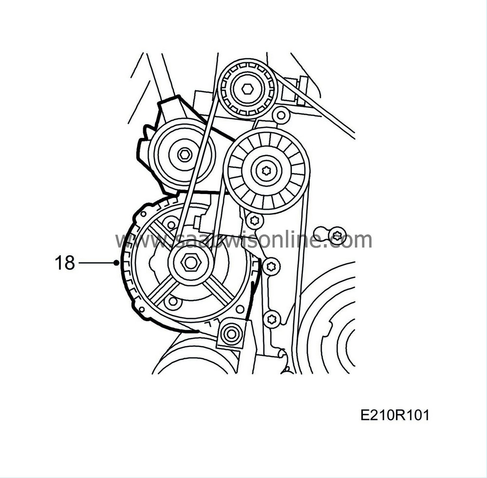
Fit the generator bracket. Make sure that the adjuster sleeves in the generator bracket are tapped out approx. 1 mm to facilitate fitting. Fit the belt tensioner.
|
|
| 19. |
Tighten the bracket for the ignition discharge module connector in the rear lifting eye and the coolant pipe fitting.

|
|
| 20. |
Fit the bolt securing the coolant pipe to the thermostat housing cover.
|
|
| 21. |
Connect the coolant hoses to the cylinder head.
|
|
| 22. |
Plug in the ignition discharge module and temperature sensor connectors.
|
|
| 23. |
Fit the turbocharger retaining nuts between the exhaust manifold and the turbocharger and tighten to torque.
Tightening torque: 25 Nm (19 lbf ft) 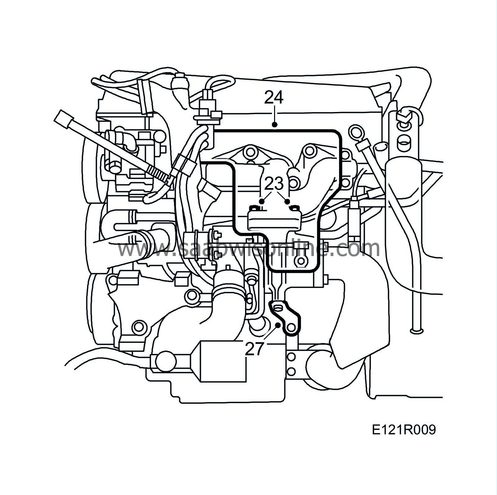
|
|
| 24. |
Fit the heat shield over the turbocharger.
|
|
| 25. |
Insert the dipstick tube.
|
|
| 26. |
Raise the car.
|
|
| 27. |
Tighten the turbocharger steady bar retaining bolts.
|
|
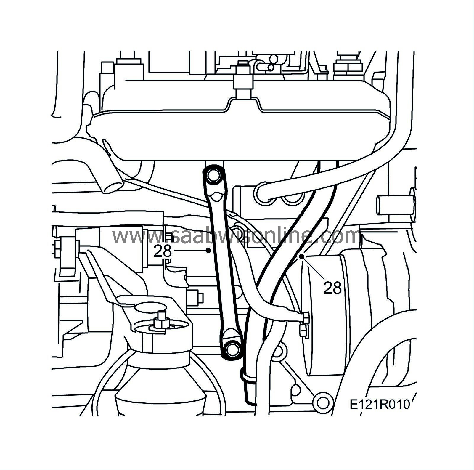
| 28. |
Tighten the intake manifold steady bar retaining bolts. Fit the dipstick tube correctly in position.
|
|
| 29. |
Lower the car to the floor.
|
|
| 30. |
Fit the fuel hoses and refit the rubber protectors.

|
|
| 31. |
Fit the crankcase ventilation nipple on the valve cover.
|
|
| 32. |
Tighten the dipstick tube, attach the throttle cable and adjust as necessary. Fit the ground connections to the cylinder head. Fit the cover over the throttle body spindle.
|
|
| 33. |
Fit the servo pump. Fit the multigroove belt and check the position of all pulleys.

Tightening torque 20 Nm (15 lbf ft) |
|
| 34. |
Release the tension of the belt tensioner using
83 95 254 Drawbar handle, hydraulic belt tensioner
and remove the allen key.
|
|
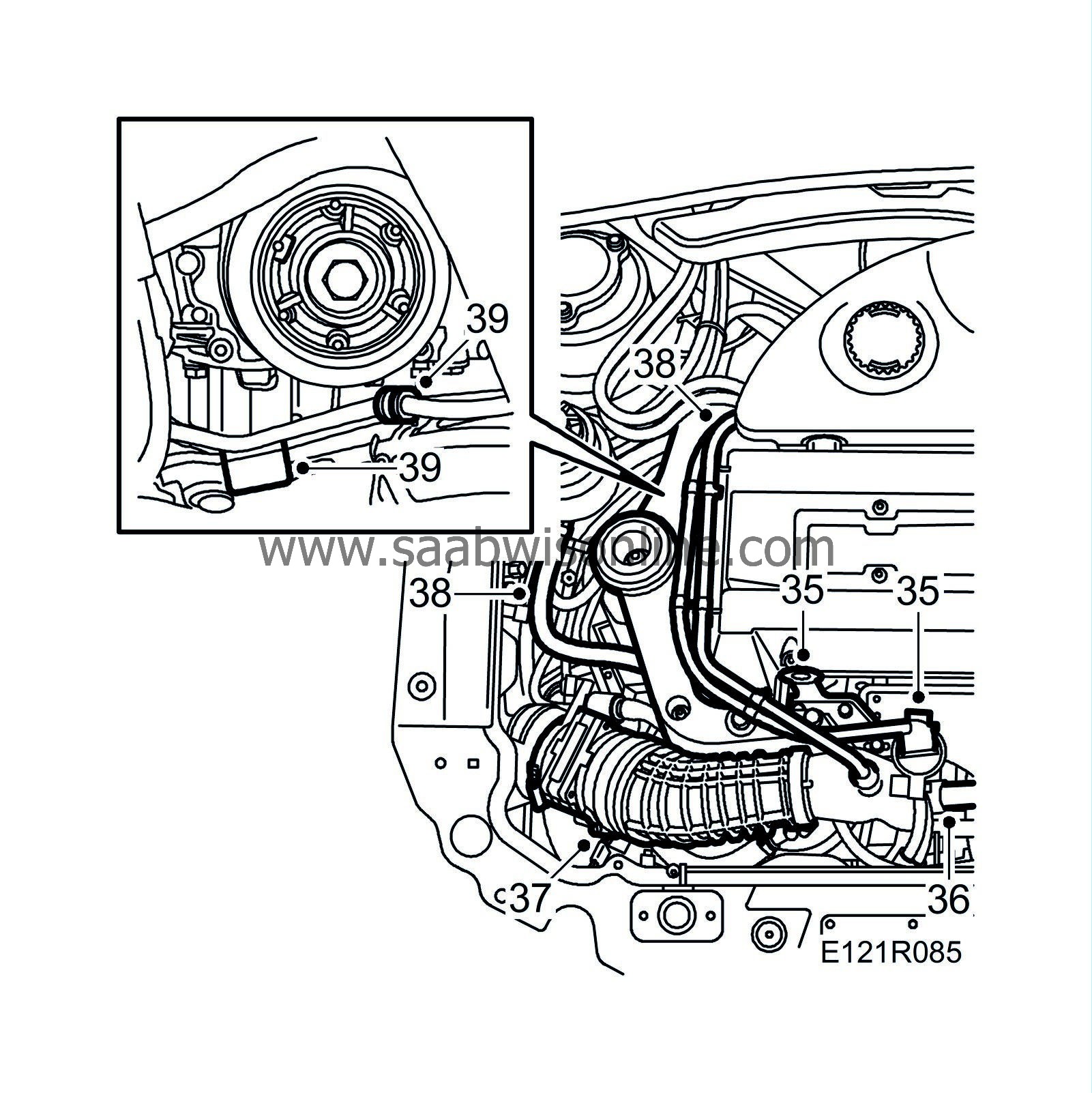
| 35. |
Fit the lifting eye, press the rubber in position and plug in the solenoid valve connector.
|
|
| 36. |
Fit the charge air pipe and bypass valve. Connect the bypass valve vacuum hose and the pressure/temperature sensor connector.
|
|
| 37. |
Fit and connect the mass air flow sensor's rubber gaiter.
|
|
| 38. |
Fit the engine mounting with yoke and the servo pump pipe bracket and tighten them, using a torque wrench.
Tightening torque bolts 47 Nm (39 lbf ft) Tightening torque nut 105 Nm (78 lbf ft) |
|
| 39. |
Remove the wedge and secure the servo pump pipe to the subframe.
|
|
| 40. |
Fit the right-hand front wheel.
Tightening torque 110 Nm (80 lbf ft)
|
||||||||||
| 41. |
Fit the crankcase breather pipe.
Tightening torque banjo connection 24 Nm (18 lbf ft) Tightening torque, mounting against camshaft cover 11 Nm (8 lbf ft) |
|
| 42. |
Connect the negative battery cable. Check that the radiator's drain plug is properly tightened. Top up with coolant and check the system for leaks.
|
|
| 43. |
Check the coolant and oil levels. Top up if necessary.
|
|
| 44. |
Remove the protective covers from the wings and check that the engine bay is clean.
|
|
| 45. |
Lower the car to the floor.
|
|
| 46. |
Bleed the cooling system as follows.
|
|
| 47. |
Fill with coolant. Do not forget to shut the drain cock on the radiator first. Refer to
Coolant
for mixtures. Close the cap.
|
|
| 48. |
Start the engine and run it warm with the heater control on max.
|
|
| 49. |
Check the coolant level. Top up if necessary.
|
|
| 50. |
Check all functions. Test drive the car.
Reset the clock and radio code. Calibrate the ACC. |
|

