Mass air flow sensor
| Mass air flow sensor |
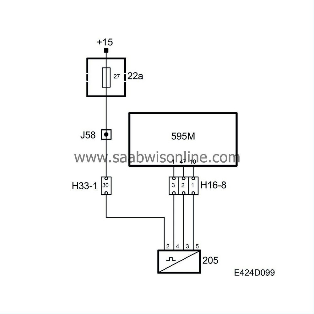
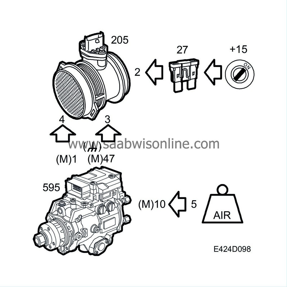
The pins are connected as follows:
| 1. |
Power supply
|
|
| 2. |
Sensor ground
|
|
| 3. |
Power supply
|
|
| 4. |
Air mass voltage
|
|
The measurement is carried out as follows. Some of the sensor's air flow is channelled past a gauge plate. The surface of this gauge plate consists of a thin, semi-conductor membrane. A heating element and a number of temperature sensors sit on the membrane. The heating element consists of a resistor that, when supplied with power, gives off heat. Together with the resistor, there is a temperature sensor that allows for exact control of heat development in the heating element. The temperature of the heating element is regulated based on the temperature of the incoming air.
Two additional temperature sensors also sit on the membrane, one upstream and one downstream from the heating element (as seen from the direction of the air flow). If no air flows past the membrane, the temperature over the entire surface of the membrane will be the same. The temperature sensors up and downstream from the heating element will register the same temperature.
When air begins to flow through the mass air flow sensor, the membrane will cool upstream from the heating element, which will be registered by the temperature sensor on the membrane. Downstream from the heating element, the membrane and the temperature sensor will remain as warm as before the air started to flow.
By measuring the differences between the two temperature sensors (up and downstream) in the air flow, air mass can be calculated.
By seeing which of the two temperature sensors is warmer and colder respectively, the direction of flow can also be determined. All necessary calculations are done in the mass air flow sensor.
The signal, which is available to the engine control module, is the completely calculated air mass as well as the temperature of the incoming air.
The inner air duct has a protective mesh that separates any water that may enter and prevents function disruption by dust particles or oil mist from the crankcase ventilation.
| Diagnostics, mass air flow sensor |

System reaction to a fault
| • |
As soon as the control module detects the fault:
Limp-home with fuel doses, 30 mg fuel up to 1250 rpm. 20 mg fuel up to 2250 rpm. 0 mg fuel up to 2500 rpm. |
|
| • |
The control module engages the function "fuel limitation upon system fault"; see
Torque limitation upon DTC
|
|
| • |
The read value on the diagnostic instrument for P0100, P0102 and P0103 is 1500 mg/combustion.
|
|


