System overview
| System overview |
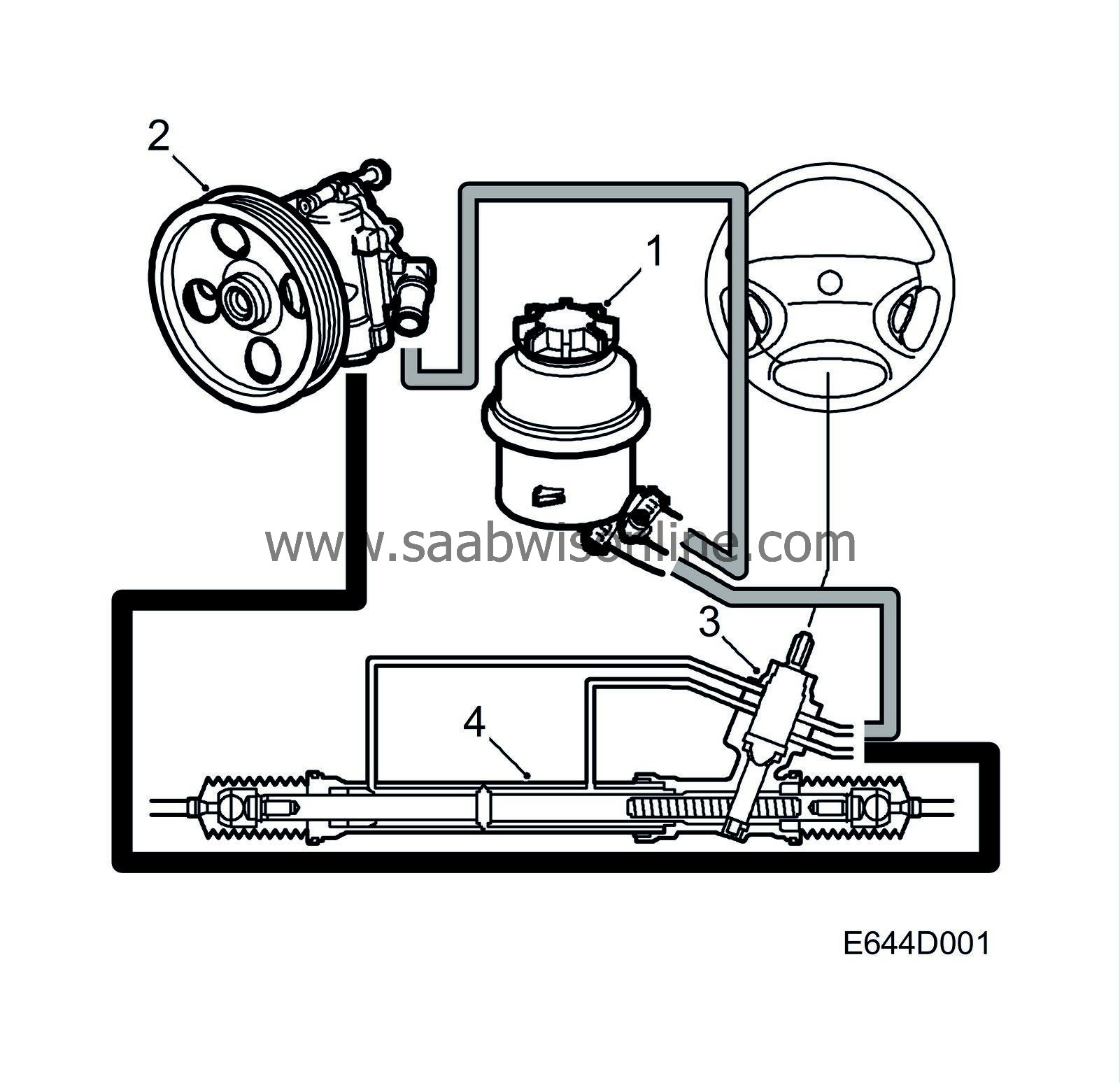
1 Power steering fluid reservoir
2 Power steering pump
3 Control valve
4 Servo cylinder
The power-assisted steering gear is of the rack-and-pinion type consisting of control valve and servo cylinder in a common housing. Together with the power steering pump and power steering fluid reservoir, these are the main components of the system.
Power steering fluid is pumped from the power steering pump to the control valve where, depending on which way the steering wheel is turned, it is directed to either the right or the left side of the servo cylinder. The steering servo fluid inside the cylinder acts on the rack's piston, thus providing power assistance to the rack-and-pinion steering gear.
The mechanical components of the steering gear are lubricated by high-viscosity grease and sealed from the hydraulic circuit and other parts of the system by seals and rubber gaiters.
| Control valve |
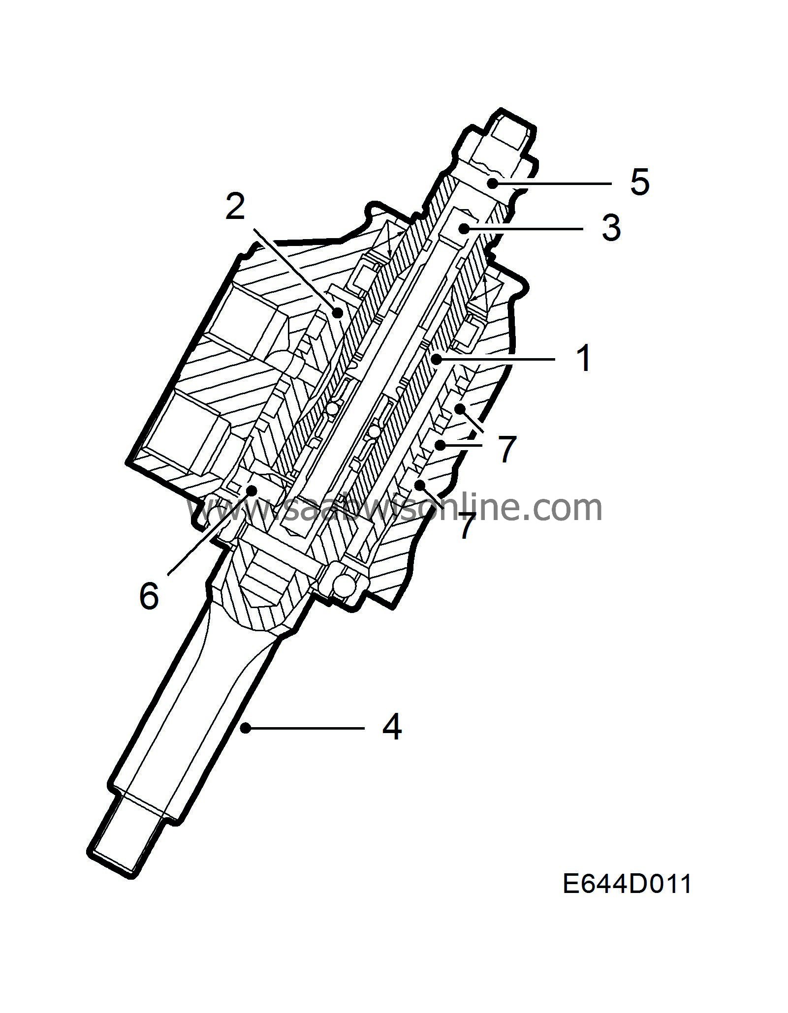
The control valve consists of a valve spool (1), a sleeve (2), a torsion bar (3) and a pinion (4). The steering column's intermediate shaft is connected to the valve by means of a universal joint. The torsion bar is connected to the upper end of the valve by means of a pin (5). The other end of the torsion bar is a press fit in the pinion. The sleeve is secured to the pinion by a pin (6) and follows the rotation of the pinion exactly. There is also a fail-safe connection between the valve spool and the pinion.
The sleeve has three radial grooves (7), the power steering fluid being pumped to the middle one. When the steering wheel is in the straight-ahead position, the control valve is open and the fluid flows up through the valve and back to the power steering pump via the chamber above the sleeve.
The upper end of the pinion is supported in a needle bearing and the lower end in a ball bearing. A plastic bush is fitted between the valve sleeve and pinion.
A spring loaded plunger presses the rack against the pinion.
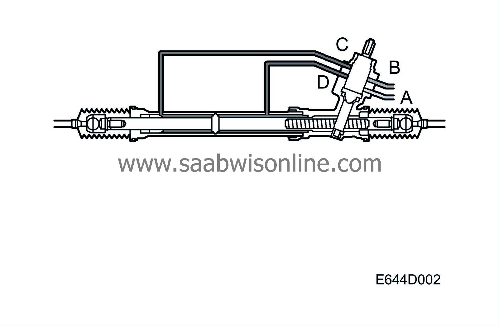
The valve housing, which is part of the rack housing, has four hydraulic connections for the flow of power steering fluid: Servo delivery from the power steering pump (A), return to the power steering fluid reservoir (B), to the servo cylinder when turning right or from the servo cylinder when turning left (C) and to the servo cylinder when turning left or from the servo cylinder when turning right (D).
When the steering wheel is turned, the movement is transferred via the torsion bar to the pinion. Since the torsion bar twists slightly, there will be a difference between the degree of rotation of the valve spool (which follows the rotation of the intermediate shaft) and the sleeve which is fixed to the pinion. As a result, the fluid can no longer flow through the control valve and back to the power steering fluid reservoir directly. Instead, delivery and return passages open for the servo cylinder.
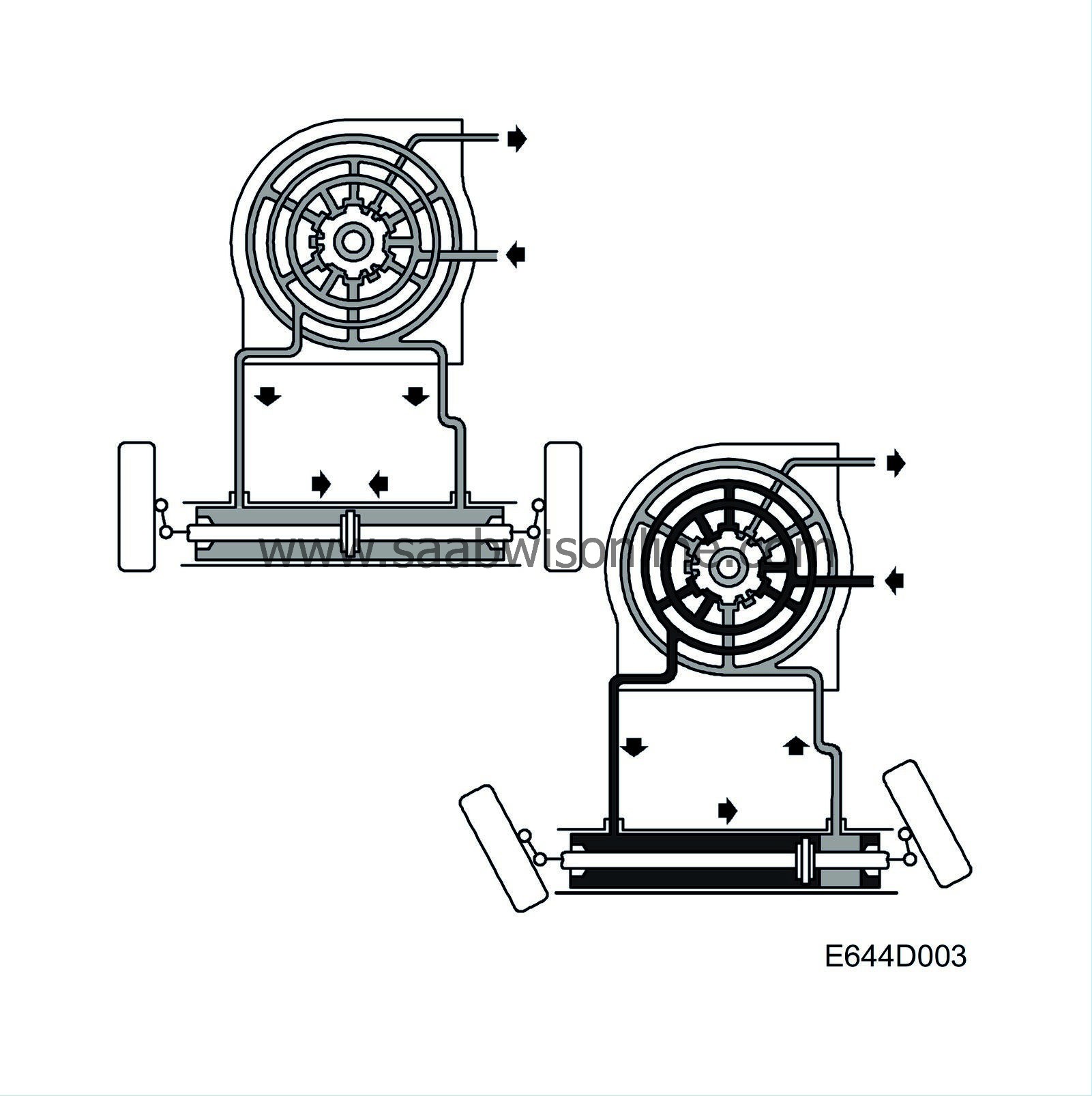
During a left turn, servo fluid is pumped to the left side of the servo cylinder via the radial groove in the upper sleeve. The servo fluid passes through the valve to the area above the spool and back to the power steering fluid reservoir. During a right turn, the procedure is the opposite.
As long as the torsion bar is twisted, power steering fluid will act on the rack to provide power assistance. The difference between the valve spool and the sleeve will be reduced when the power steering fluid acts on the rack in the same direction as the pinion. When this difference no longer exists, the return passage through the valve is opened again and the servo fluid can flow directly back to the power steering fluid reservoir.
A certain flow of power steering fluid through the valve is always present, except when the steering wheel is turned to full left or right lock. This is necessary for the control valve in the power steering pump to operate and it also helps to cool the fluid.
| Servo cylinder |
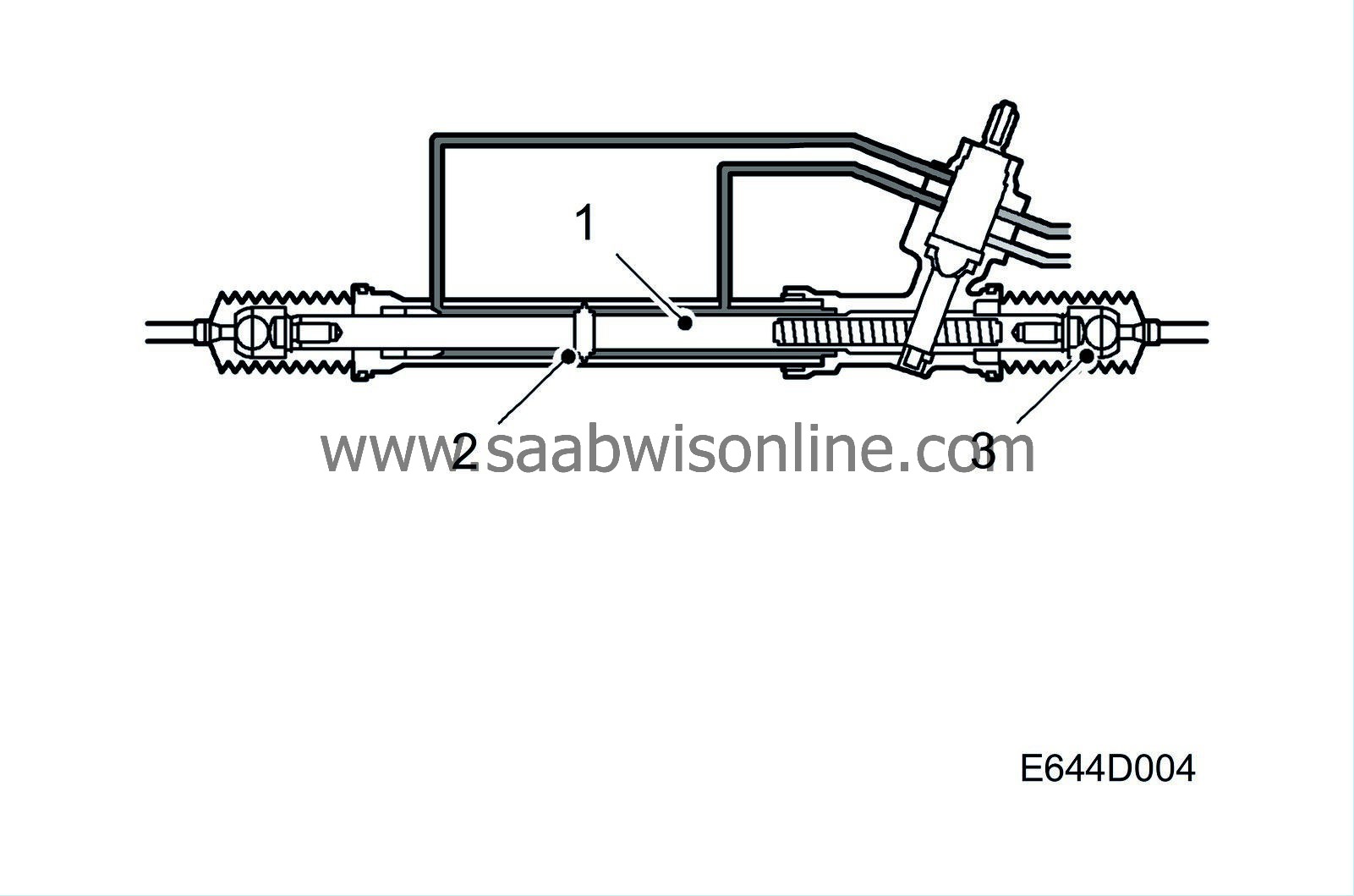
The cylinder is part of the rack housing. The rack (1) is equipped with a piston (2) complete with seals. For the flow of power steering fluid to and from the control valve there are two connections on the servo cylinder, one on each side of the piston. For turning right, power steering fluid is pumped to the right-hand section of the servo cylinder.
Piston and rack are forced to the left and power steering fluid is discharged from the left-hand section of the servo cylinder. The rubber gaiter on the left-hand side is distended at the same time as the one on the right-hand side is compressed.
Movement of the rack is transferred via the inner ball joints (3), track rod and outer track-rod ends to the steering arms of the steering swivel member. Both the inner ball joints and the outer track-rod ends are lubricated for life and self-adjusting, with no further lubrication or adjustment being necessary or possible.

