SRS control module
| SRS control module |
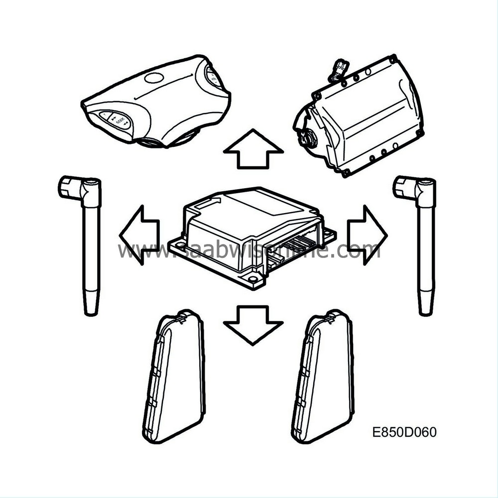
The primary role of the control module is to recognise a crash situation and then trigger the correct airbag with the right force and/or right seat-belt tensioner. The control module contains two acceleration sensors, a microprocessor, backup power, and a voltage converter.
The primary acceleration sensor measures acceleration and retardation forces in the car both longitudinally and laterally. The control module retrieves information from two front impact sensors located in the front of the car to detect impact intensity as early as possible. A side impact sensor in each of the front doors sends the control module information on impact intensity from the side. This data is used together with signals from the belt buckle switches to calculated if and how the airbags and seat-belt tensioners should be activated.
If retardation exceeds the values defined for collision, the processor will prepare to trigger the electric detonators. For ignition to occur, a secondary acceleration sensor, which only measures forces longitudinally along the car, must confirm that there is sufficient impact intensity.
When the control module has defined a sufficiently great impact intensity, the seat-belt tensioners are activated first. If the collision has great enough force, the front airbags are also activated. The seat-belt tensioners can also be triggered by a rear-end collision.
If the seat-belt buckle is not locked or the seat is far away, the airbag will be triggered earlier. The seat-belt tensioner will not be activated if the belt buckle is not locked.
In the event of a side-on collision, the side impact sensor registers a pressure change in the front doors. If the pressure build-up per time unit matches the limit values defined for collision, impact information is sent on to the control module. If the control module's internal acceleration sensor determines there is sufficient impact intensity, the control module triggers the seat-belt tensioners and the side airbag on the side of the collision.
The control module can be reused no more than two times after triggering of the belt tensioner and/or side airbag, i.e. the side airbags and belt tensioners can be activated a total of three times before the control module is considered used.

| • |
driver airbag, dual stage
|
|
| • |
passenger airbag, dual stage
|
|
| • |
seat-belt tensioner, driver
|
|
| • |
seat-belt tensioner, passenger
|
|
| • |
side airbag, driver
|
|
| • |
side airbag, passenger.
|
|
The activation times in a collision may be different for the different circuits.
| Conditions |
Front airbags: Stage 1 means that only 80 % of the maximum pressure is used. The airbags can be activated individually at stage 1 or stage 2, depending on the conditions. See below.
Conditions for stage 1:
| • |
Low impact intensity.
|
|
In situations in which the front airbags are only activated at stage 1, there is a safety-activation of stage 2 after 100 ms. This disarms the airbags so that no charge is activated after the impact.
Stage 2 includes activation of stage 1 (80% of max. pressure) and the drive charge for stage 2, which uses the final 20% of the maximum pressure.
The front airbags are activated in two stages with a 5 to 20 ms delay.
Conditions for stage 2:
| • |
High impact intensity.
|
|
The following applies for both stages:
| • |
The front airbag is triggered earlier if the belt buckle is not locked.
|
|
If the driver or passenger belt buckle is not locked, the belt tensioner is not activated.
In the event of impact to one side, the side airbag is only activated on the side of the impact, but all belt tensioners are activated.
Cars equipped with ONSTAR (certain markets) use a bus message "Airbag triggered" and are electrically linked to the SRS (Supplemental Restraint System) control module.
| Backup power |
The control module has built-in backup power. This backup power provides the control module with power 150 ms after the normal power supply is cut off.
Three capacitors provide the system with power 150 ms after +15 has been cut off. The side impact sensors are deactivated, but bus communication is functional during this time period.
| On-board diagnostics |


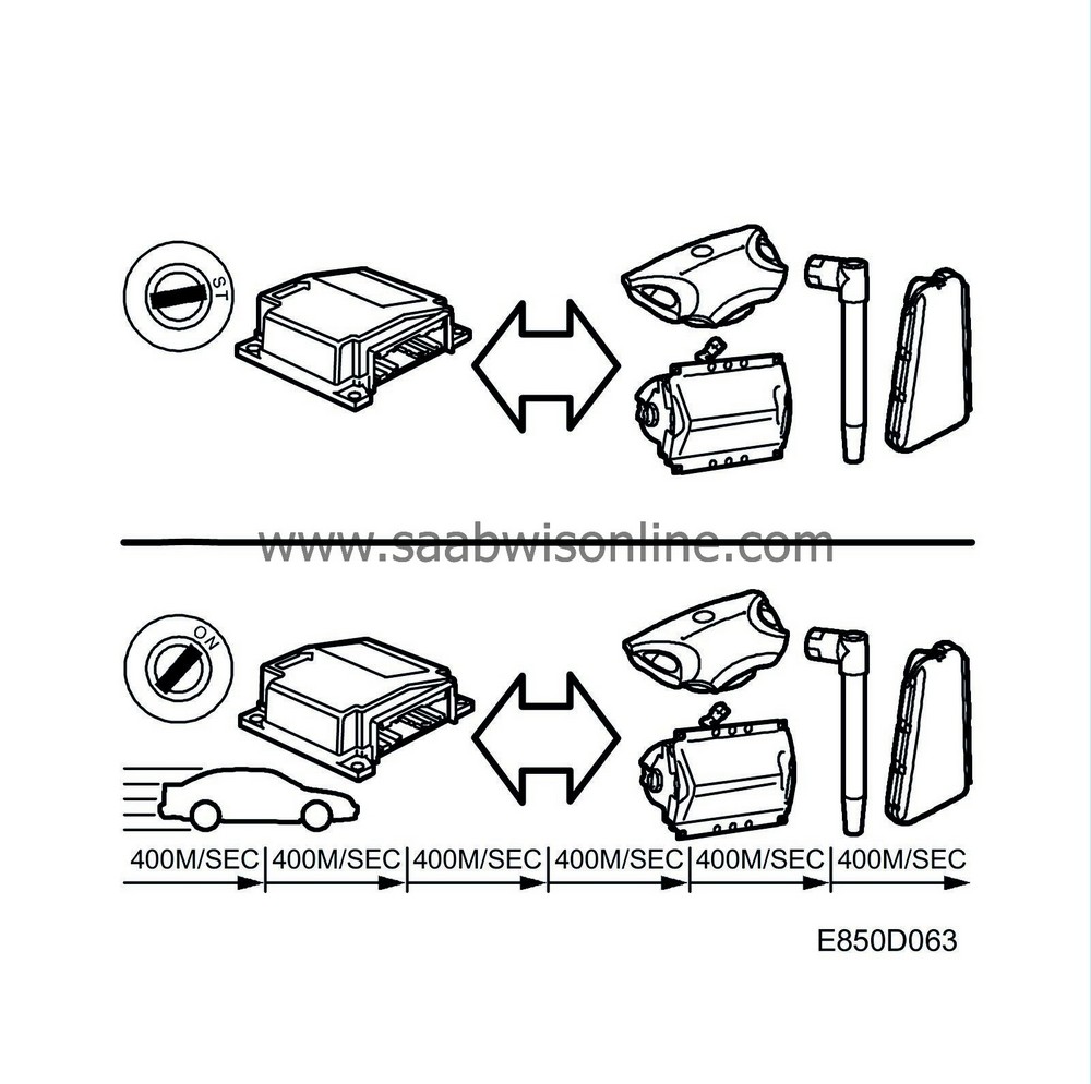
When the ignition is in the ON position and the system has power, the control module runs on-board diagnostics for 3.5 seconds. As a safety precaution, the airbags cannot be triggered during this time.
The following are checked during the self-test: electric detonators with wiring harness, power supply, airbag warning lamp, microprocessor, side impact sensors and front impact sensors.
Upon supply of power, the airbag warning lamp lights during the first test for 3-4 seconds to check the lamp. On-board diagnostics then continue as long as power is supplied. The airbag warning lamp has no diagnostics.
There are DTCs in the system to cover all sensors, wiring harnesses, airbags, seat-belt tensioners and internal control module faults.
The control module can measure shorting to ground and B+ as well as resistance too low and too high in all ignition circuits. In case of a system malfunction, the Airbag warning lamp is illuminated.
The control module monitors the diagnostic trouble code conditions at different intervals, depending on the diagnostic trouble code concerned.

These are the different types of monitoring:
|
On starting
|
For 10 s after ignition is switched to ON position.
|
|
Periodically
|
Every 400 milliseconds under normal operating conditions
|
|
Non-continuous monitoring
|
Event-determined, for example in the event of a DTC from a side impact sensor.
|
After activation of the driver and passenger airbags, the control module will no longer be serviceable. The SRS control module therefore cannot be reused after activation of one of the front airbags.
The control module can be reused no more than two times after activation of a seat-belt tensioner and/or side airbag, i.e. the side airbags and seat-belt tensioners can be triggered a total of three times before the control modules is considered unserviceable.
DTCs are generated for all activated airbags and seat-belt tensioners. The DTC for an activated front airbag cannot be cleared and the control module must be changed.

Storage of diagnostic trouble codes
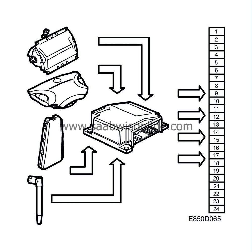
The SRS control module can store 24 DTCs in its memory.5 DTCs are reserved for:
| • |
driver airbag activated
|
|
| • |
passenger airbag activated
|
|
| • |
seat-belt tensioner activated
|
|
| • |
side airbag, driver's side, activated
|
|
| • |
side airbag, passenger side, activated
|
|

There are two types of DTCs, active and historic. An active DTC indicates a fault that is currently in the system, while a historic DTC indicates a fault that has occurred, but no longer remains in the system.
The DTCs are saved in chronologic order, with active DTCs receiving higher priority than historic. A historic DTC is saved for 250 ignition cycles (ignition off-on).
| Programming the SRS control module |

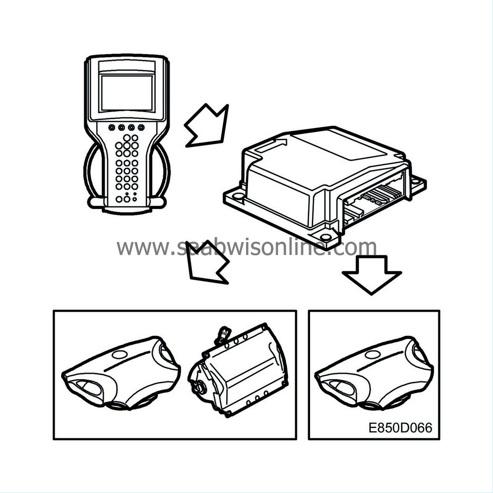
As supplied from the manufacturer, the SRS control module will not be functional until it has been programmed for the car in which it is installed. Programming entails comparing the control module functions with the hardware present in the car.
The control module checks whether the requested programming is compatible with the components that it detects electrically in the car, until the ignition is switched off. If the detected components are not compatible with the desired programming, a diagnostic trouble code will be generated. In this way it is possible to find out why the car's equipment and the desired control module programming are incompatible.
When the SRS control module has been changed, the spare parts control module must be programmed for the car in which it will be installed. This is done using a diagnostic tool.
After programming is successfully completed, the only value that can be altered is the one for OnStar/Telematic. Other values are locked in the control module.
| Power supply |

With the ignition key in the ON position, the control module receives +15 power via fuse 28 to pin 51. The control module is intended for use with a power supply between 9 and 16 V.
| Grounding |
The control module is connected to ground via pin 52 and the three retaining screws. No ground cables from other systems may be connected to the retaining screws as this could cause malfunctioning of the SRS system.
A poor ground connection will not cause a diagnostic trouble code to be generated. When connection to ground is restored after having been interrupted, it corresponds to power turn-on and the control module again runs through the on-board diagnostics program. The airbag warning lamp will then lights up for 3-4 seconds.
| Connector |

The control module connector is equipped with 5 short-circuit sheets, which in pairs short the leads to the front airbags' two electric detonators and the side airbags' two electric detonators upon removal of the connector. See Control module connections .


