Compressor
| Compressor |
A lot of power is required to achieve this pressure increase, and the compressor retrieves power from the crankshaft via a belt circuit that also drives the alternator and the steering servo pump, among others. The compressor is engaged and disengaged by an electromagnetic controlled magnetic clutch which is built into the compressor pulley. In the magnetic clutch coil, there is an overheating protection which activates if the clutch overheats (184°C). If the overheating protection has been activated, the solenoid coil must be replaced as the overheating protection cannot be reset.
The compressor has a variable swept volume, also called displacement. A compressor with variable swept volume adapts the volume displacement to the degree of cooling requ ired in the cabin at any given moment.
While the volume displacement is adapted to the cooling requirements, the evaporator temperature will also be practically constant. This means that the compressor will not engage/disengage as often as one with a fixed displacement.
When the electromagnetic clutch engages the compressor, it starts with 5% of its maximum swept volume. After engaging, the compressor increases the swept volume until it matches the required degree of cooling.
The torque required from the crankshaft increases gradually which means that there will be less of a jerk when it engages compared to a compressor with fixed displacement.
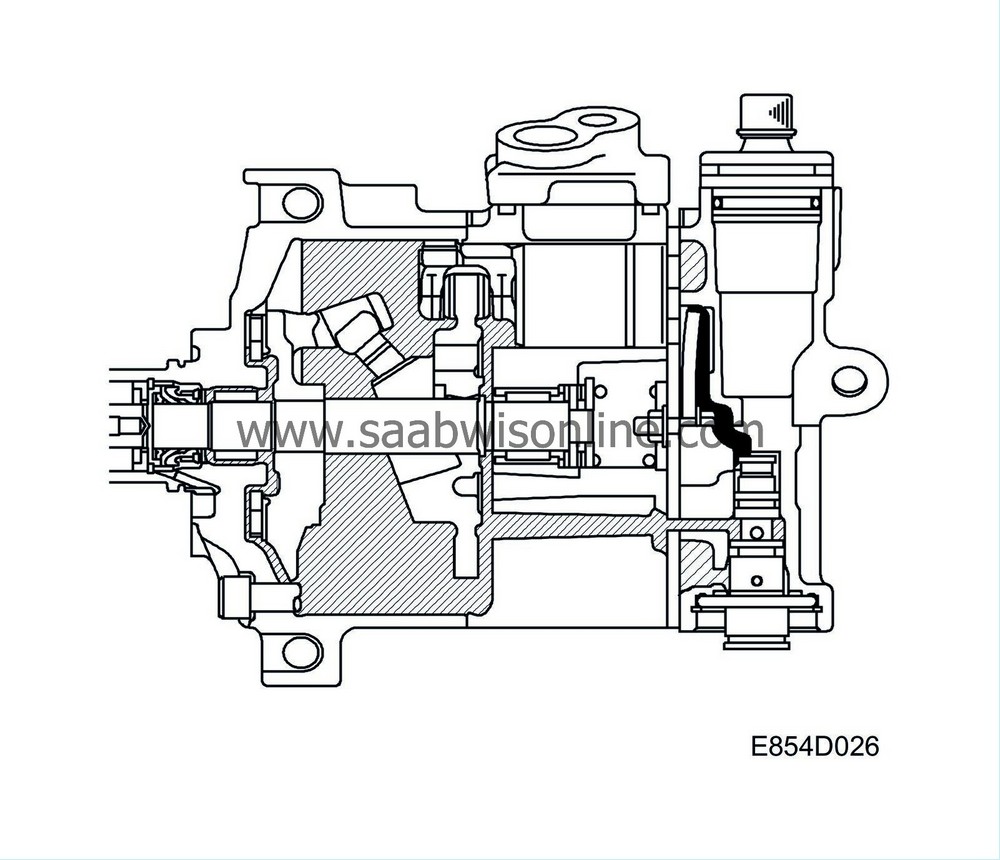
The compressor is of piston type with seven axial cylinders.
The pistons move backwards and forwards in their cylinders, creating a pumping effect on the refrigerant with the aid of intake and outlet valves. The power from the compressor rotating shaft is converted to the backwards/for wards movement of the pistons by a swashplate. The pistons are guided by skid shoes, which are in contact with both sides of the swashplate.

To change the compressor swept volume, the stroke of the pistons is adjusted. By changing the angle of the swashplate relative to the compressor shaft, the pistons travel a shorter or longer distance.
The difference in pressure between the compressor cylinders and crankcase is used to change the swashplate angle. If the pressure in the crankcase is lower than that above the pistons, the pistons and swashplate are moved axially towards the belt pulley. A link of two locating studs between the swashplate and the shaft increases the angle of the swashplate as the pistons and swashplate are moved. The increased angle increases the swept volume.
As a result, the compressor's swept volume can be adjusted by changing the pressure in the compressor crankcase.

| 1. |
Belt pulley
|
|
| 2. |
Electromagnetic clutch bearing
|
|
| 3. |
Electromagnet
|
|
| 4. |
Shaft seal
|
|
| 5. |
Radial needle bearing
|
|
| 6. |
Needle thrust bearing
|
|
| 7. |
Shaft
|
|
| 8. |
Radial needle bearing
|
|
| 9. |
Needle thrust bearing
|
|
| 10. |
Thrust spring
|
|
| 11. |
Locating stud with ball joint
|
|
| 12. |
Skid shoe with ball joint
|
|
| 13. |
Piston
|
|
| 14. |
Intake valve
|
|
| 15. |
Outlet valve
|
|
| 16. |
Control valve
|
|
| 17. |
Start spring
|
|
| Regulating swept volume |


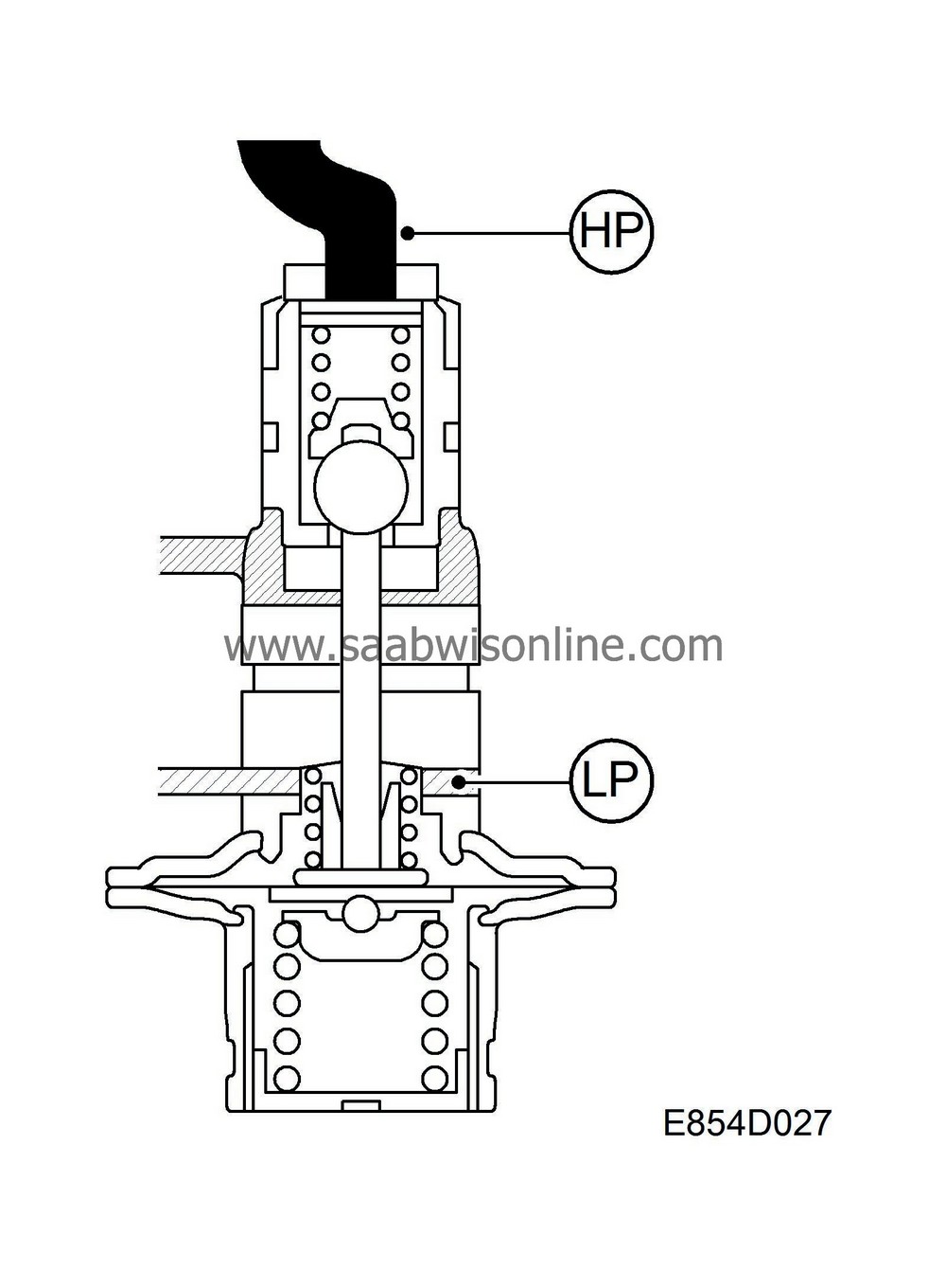
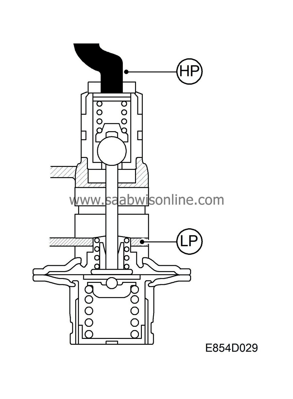
Regulation of the compressor swept volume is controlled by the regulating valve which is located on the back end of the compressor. The regulating valve strives to maintain the compressor low pressure side at a pressure of 2.6 bar.
To achieve this, the control valve changes the pressure in the compressor crankcase as follows:
| • |
At a pressure below 2.6 bar
If the pressure on the compressor low pressure side is below 2.6 bar, the regulating valve opens a passage for refrigerant from the high pressure side to the crankcase. Through a small passage in the valve disc, there is a constant small flow of refrigerant between the crankcase and the low pressure side, but the added refrigerant is greater than the amount that can pass and therefore the crankcase pressure increases. As the pressure in the compressor crankcase increases, the piston stroke decreases and therefore also the capacity of the compressor. |
|
A weak spring, called a start spring, is fitted on the compressor shaft and is used to return the pistons and the swashplate towards the valves as soon as the compressor stops operating and the pressure difference between the high and low-pressure sides evens out. In this position, the compressor delivers 5% of its maximum swept volume and the starting torque is low the next time the compressor starts.
|
|||||||


 Warning

