(210-2520) Changing bolts for chain tensioner/chain guides
Symptom: Engine noise.
|
TECHNICAL SERVICE BULLETIN
|
|
Bulletin Nbr:
|
210-2520
|
|
Date:
...........
|
December 2004
|
|
Market:
|
enligt separat lista
|
|
|
Changing bolts for chain tensioner/chain guides
|
|
Customer Satisfaction Campaign 154 36
|
Cars in stock must be rectified before delivery.
A personal communication must be sent to the owners of cars already delivered requesting them to get in touch with the nearest Saab garage as soon as possible to have the fault rectified.
Saab 9-5 M05 with engine alternative B205/B235 within VIN intervals 53501148 - 53501562 and 53511329 - 53515417
Not all cars in the interval are affected
Bolts that risk losing their clamping force have been fitted on the tensioner for the balancer shaft chain and the chain guides. If these bolts come loose they could cause engine damage.
Symptom description
Engine noise.
Fully synthetic oil SAE 0W-30, GM LL A 025, API SL and ACEA A1/A5 4 litres/car
Saab Longlife Coolant approx. 4 litres/car
79 78 141 Bolt x6/car
91 30 600 Oil pump O-ring
30 551 914 Water pump O-ring x2/car
46 85 244 Oil cooler O-ring, x2/car
90 297 970 Loctite flange sealant 518, sufficient for 2 cars
16-83 95 691 Loctite Silicon flange sealant 5970, sufficient for 100/cars
92 150 435 Coolant pipe gasket B205E/235E x2/car
11 066 422 Coolant pipe gasket, B235R/L x3/car, B205E/B235E x1/car
59 59 242 Coolant pipe gasket
51 25 000 Turbo exhaust pipe nut, x3/car
90 490 362 Intake O-ring
75 08 690 Chain tensioner O-ring
91 32 937 Oil plug gasket
For fitting the modification identity plate (not US/CA):
12 785 148 Modification identity plate
93 160 907 Cleaning agent Motip Dupli, aerosol 400 ml (sufficient for 50-100 cars)
Procedure
(Not US/CA) Before proceeding, check box B1 of the modification identity plate. From and including M04 the table "Table of Modifications" can be found in the car's Warranty and Service Book. A modification identity plate must be fitted in accordance with the section "Fitting the modification identity plate" where local directives require the marking of the car. If the box is not marked, continue as follows.
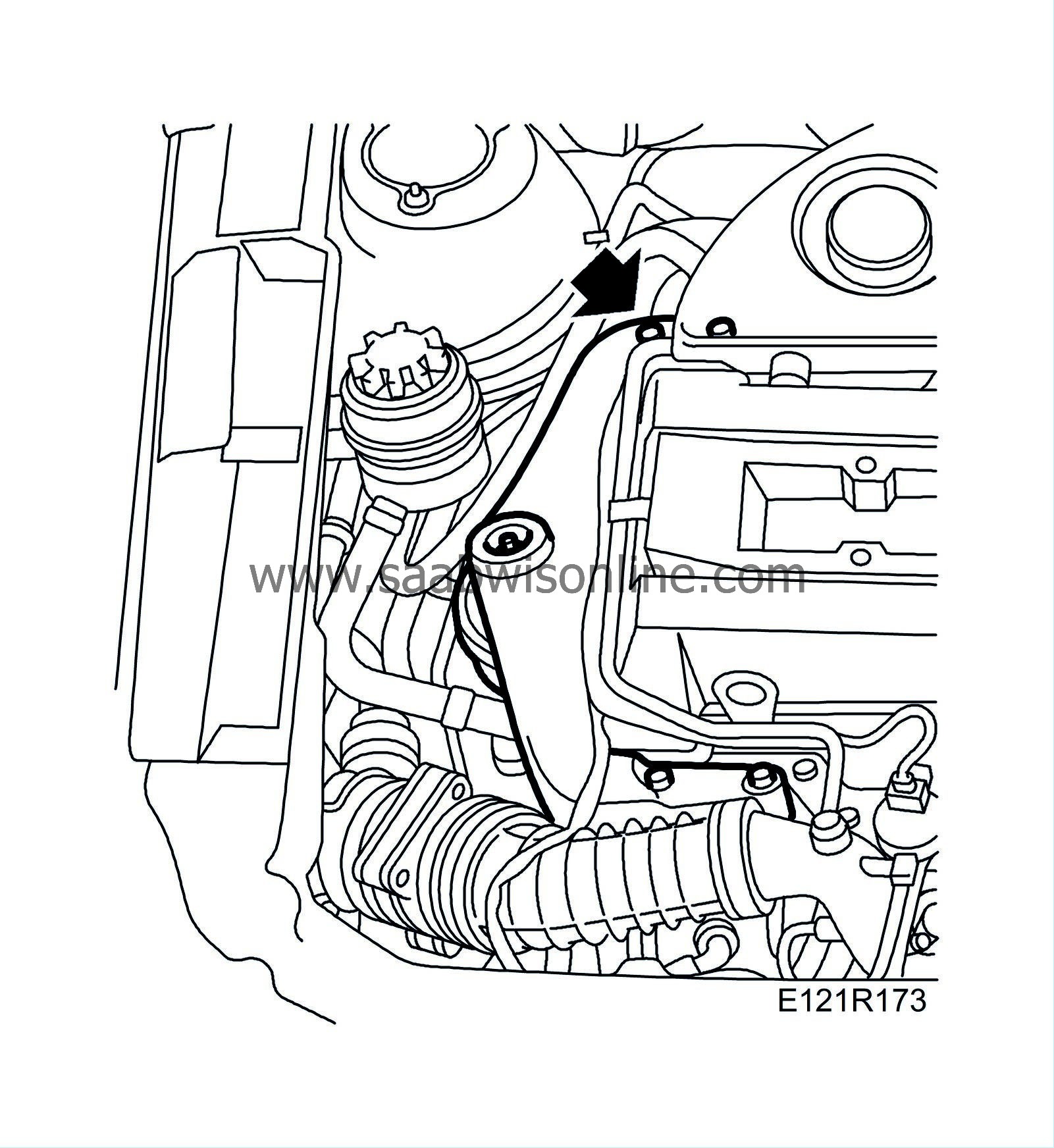
US: Before taking any measures, check whether there is a white mark on the bolt as illustrated. If not, proceed as follows.
|
1.
|
Place wing covers on the wings and front.
|
|
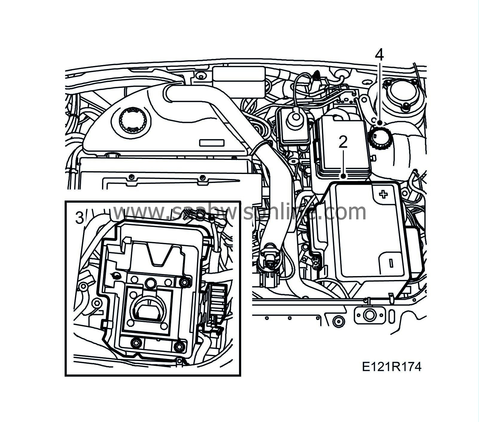
2.
|
Remove the battery cover and the battery.
|
|
3.
|
Remove the battery tray.
|
|
4.
|
Open the expansion tank cap.
|
|
5.
|
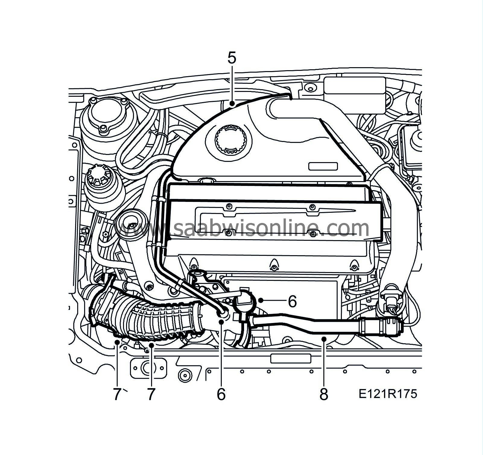
Remove the upper engine cover.
|
|
6.
|
Remove the crankcase ventilation pipe from the turbo intake pipe. Unplug the connector to the solenoid valve.
|
|
7.
|
Remove the mass air flow sensor and the intake hose
|
|
8.
|
Remove the by-pass valve with pipe.
|
|
9.
|
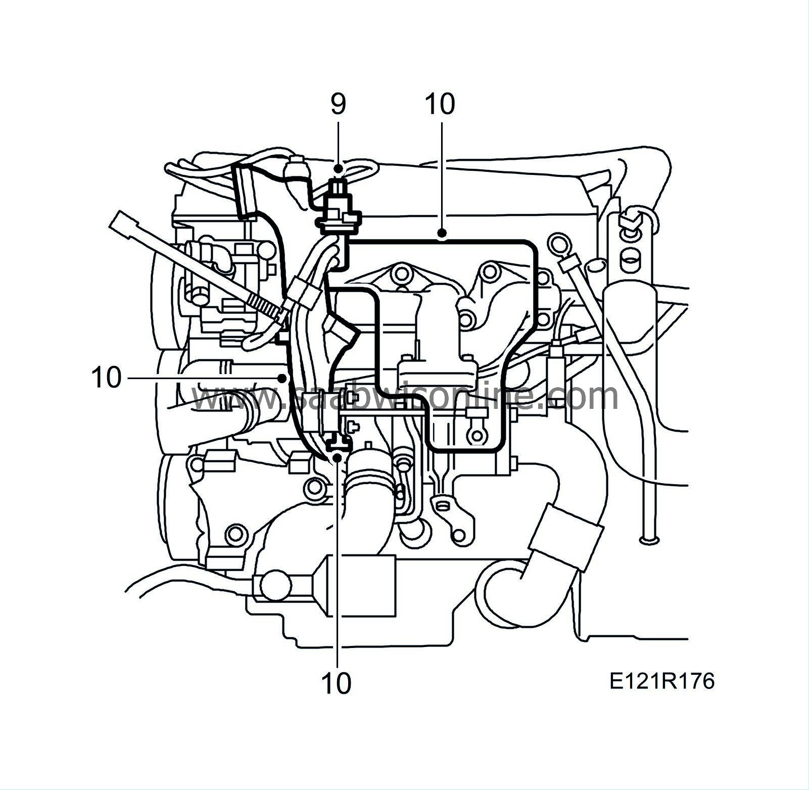
Remove and move aside the engine lifting eye and the solenoid valve.
|
|
10.
|
Remove the turbo heat shield. Remove the turbo intake pipe.
|
|
11.
|
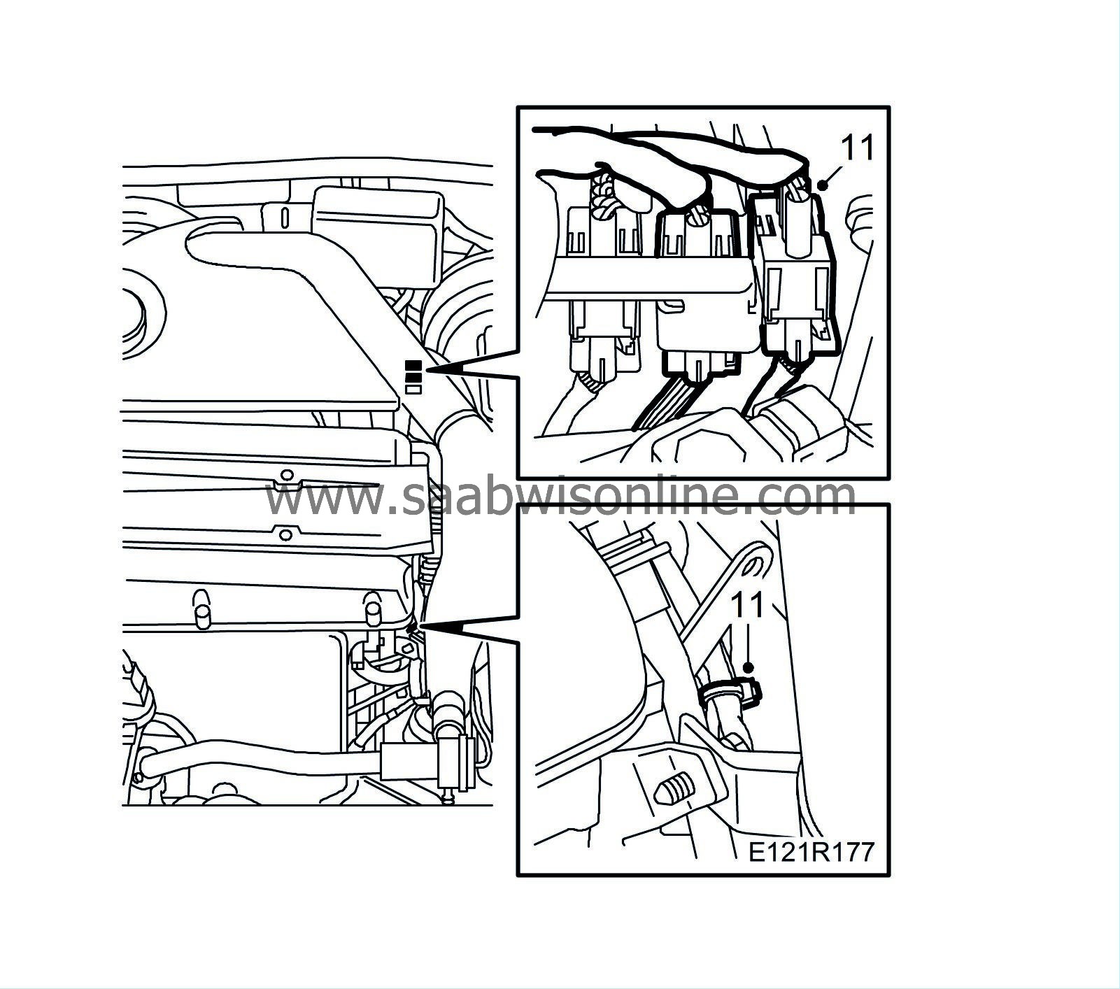
Remove the oxygen sensor connector and the cable tie.
|
|
12.
|
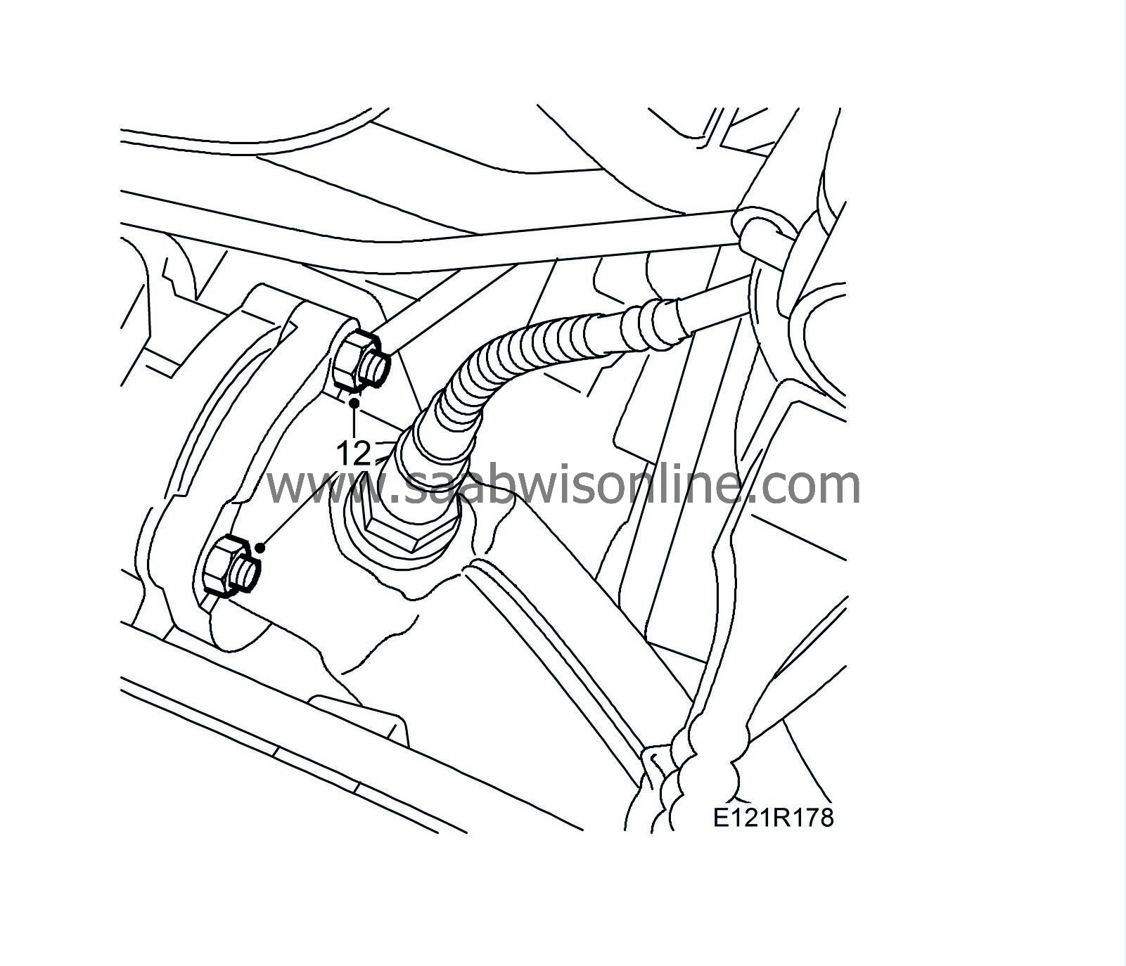
Remove the two upper nuts on the front exhaust pipe.
|
|
13.
|
Man:
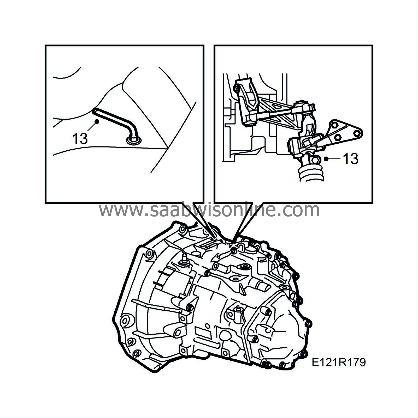
Lock 4th gear in the gearbox by fitting a 87 92 335 Lock pin. Detach the clamp slightly and pull the selector rod out from the linkage.
|
|
14.
|
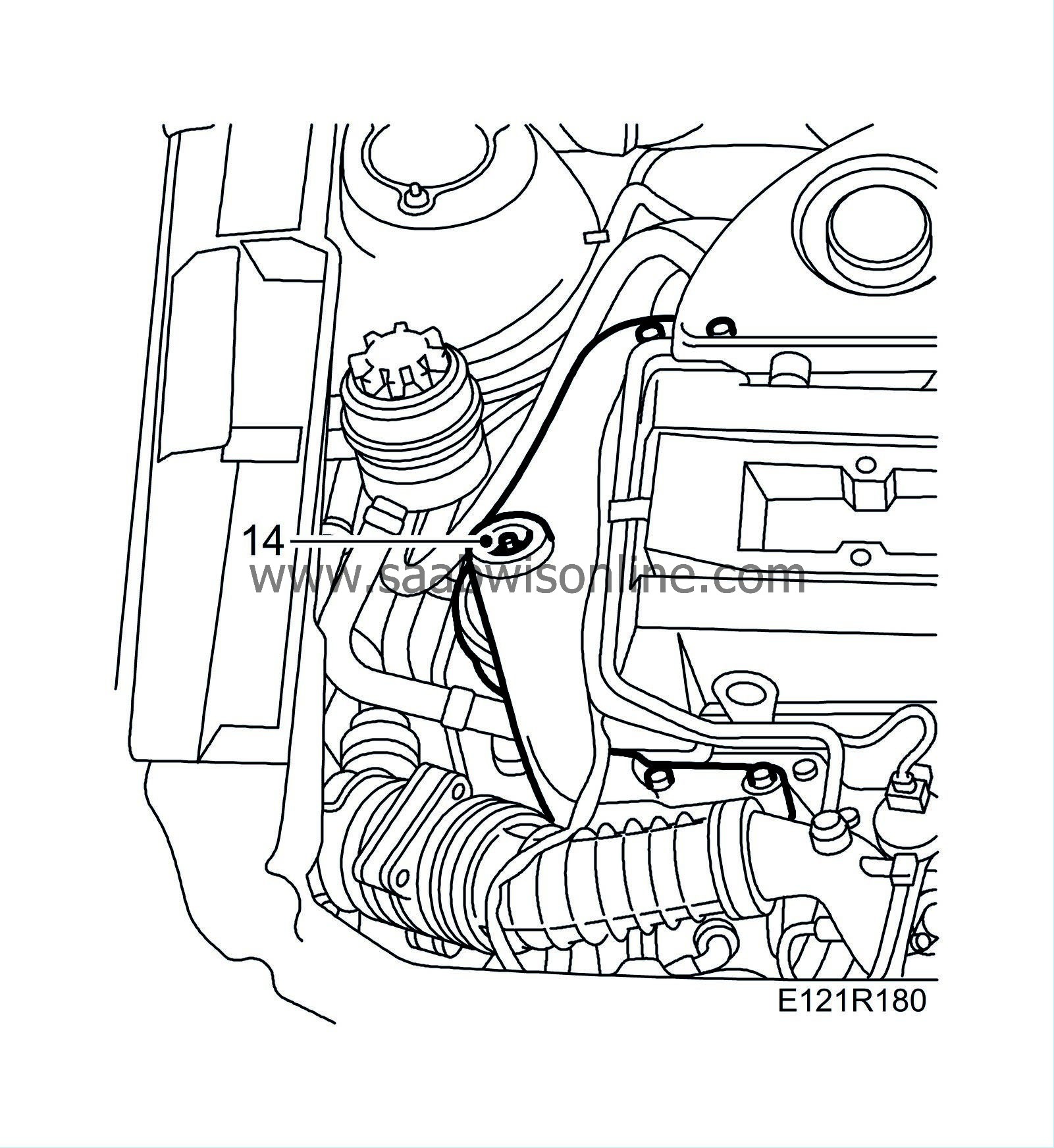
Remove the nut and washer on the right-hand engine pad.
|
|
15.
|
Raise the car and remove the right-hand front wheel.
|
|
16.
|
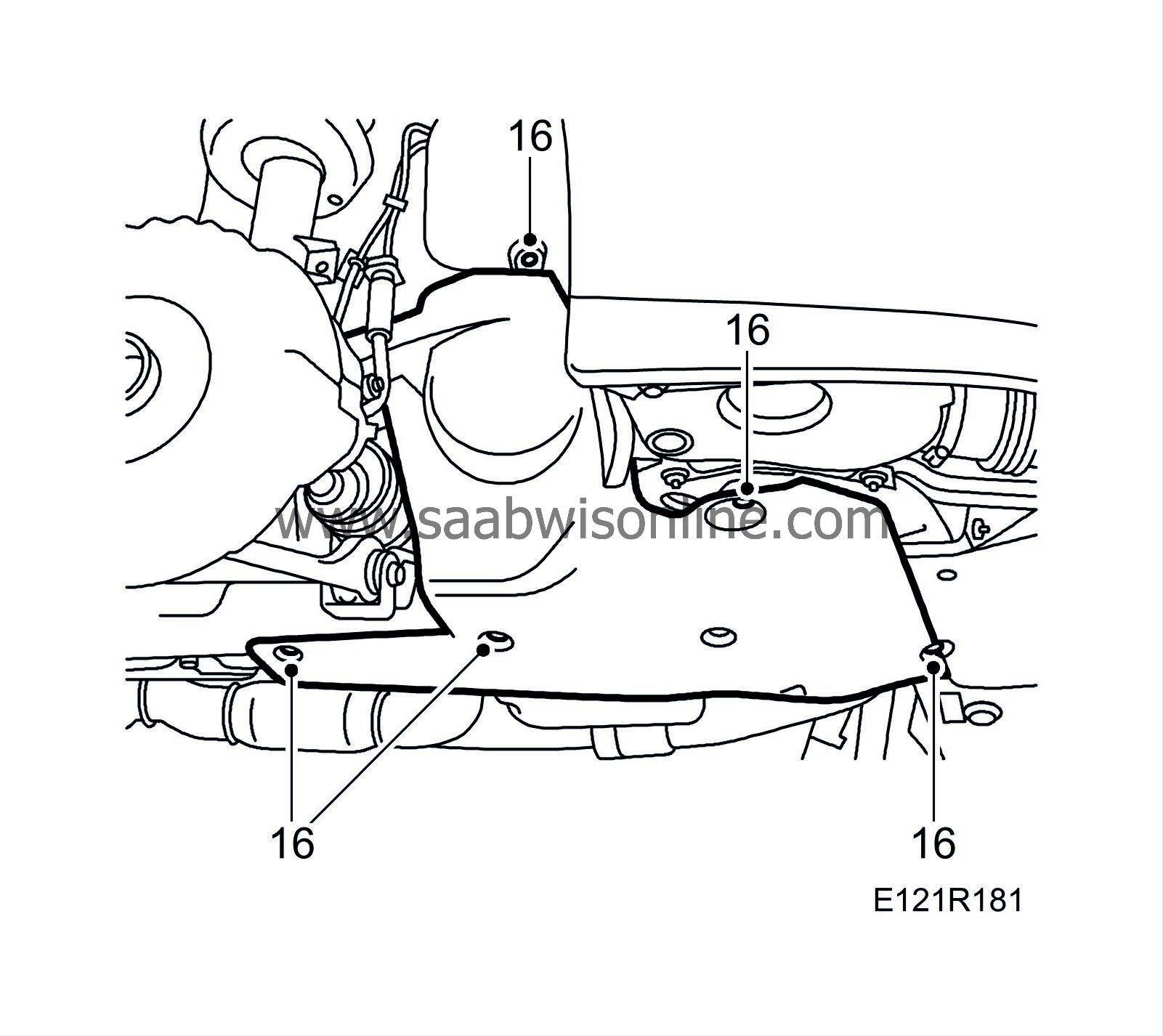
Remove the right-hand belt circuit cover. Remove the fixings for the headlamp position sensor (optional) and move the sensor aside.
|
|
17.
|
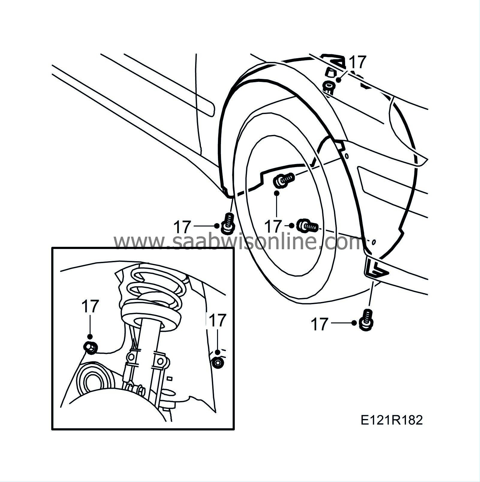
Remove the right-hand wing liner.
|
|
18.
|
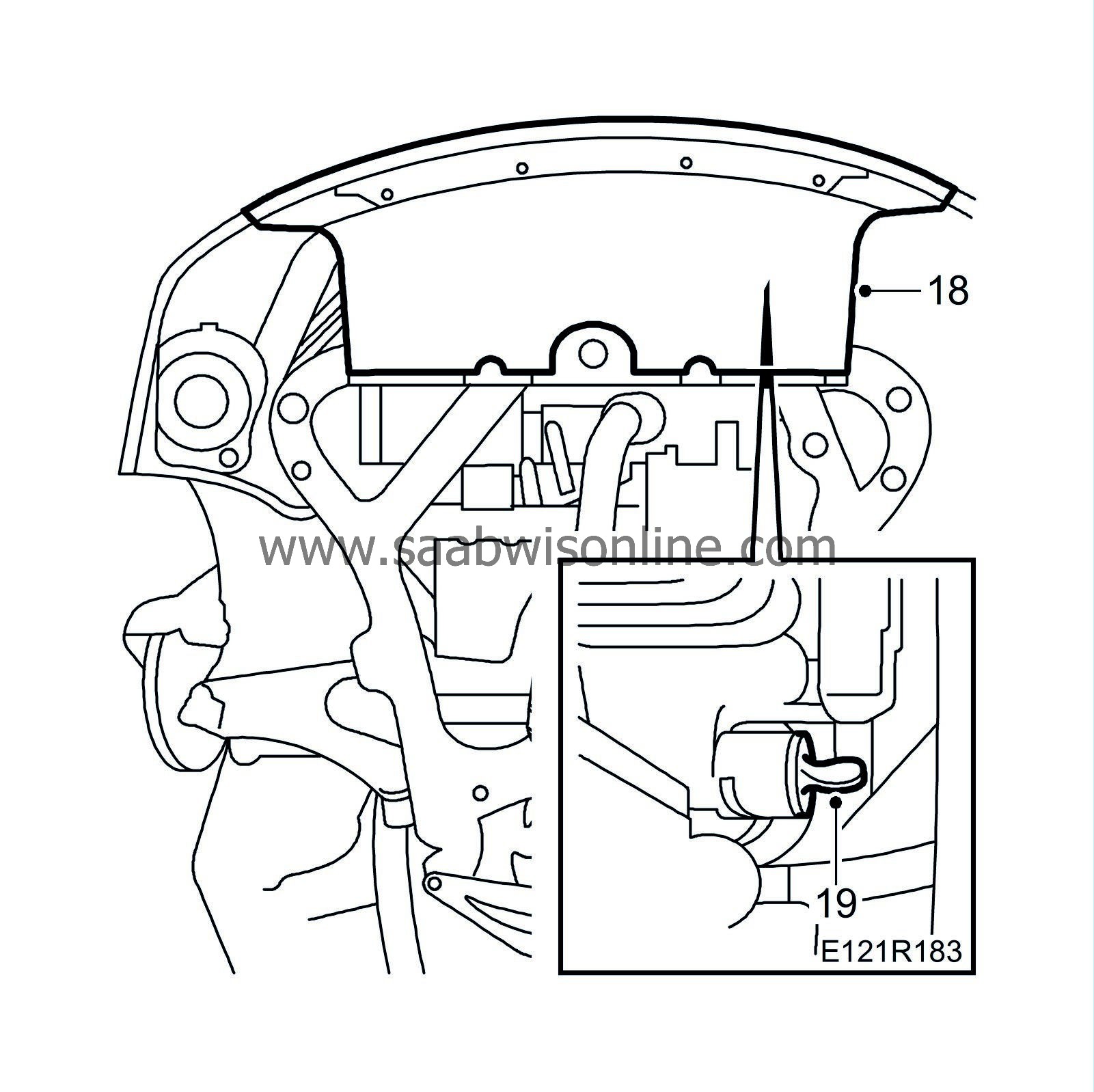
Remove the front spoiler shield.
|
|
20.
|
Place a receptacle under the car and drain the engine oil. Fit the oil plug with a new gasket.
Tightening torque 25 Nm (19 lbf ft)
|
|
21.
|
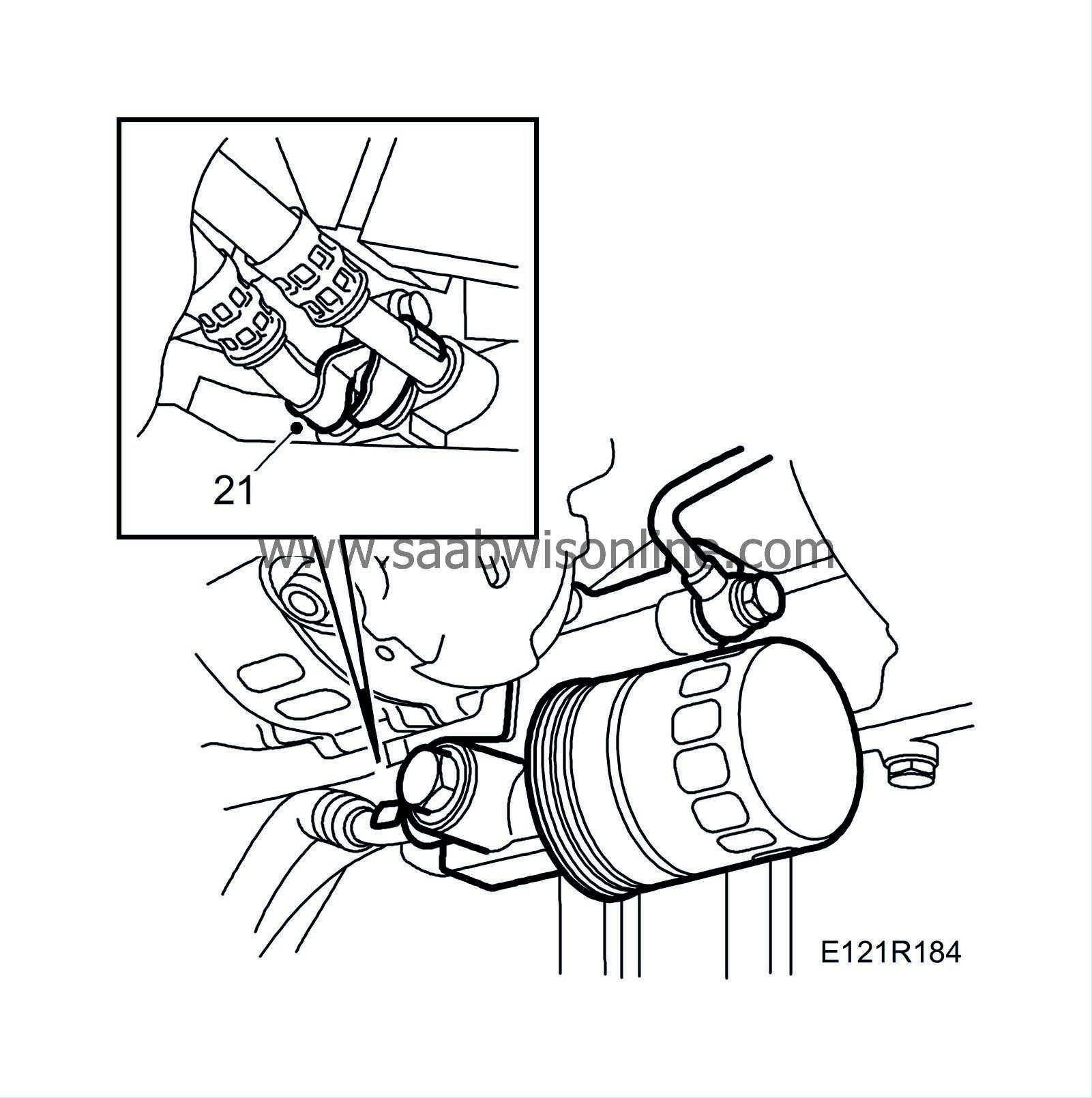
Remove the oil pipes at the oil filter adapter housing.
|
|
22.
|
Remove the front exhaust pipe.
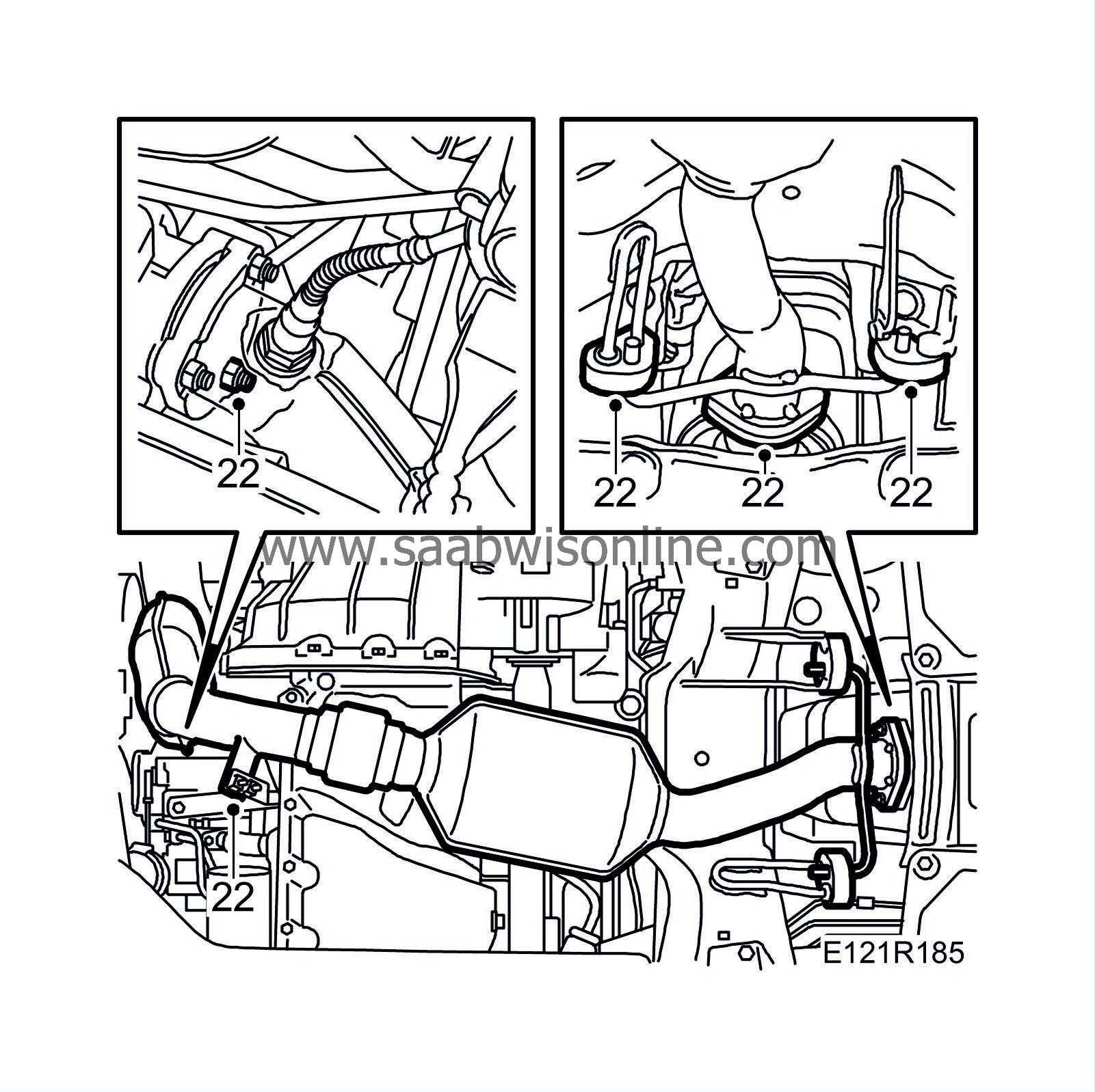
|
|
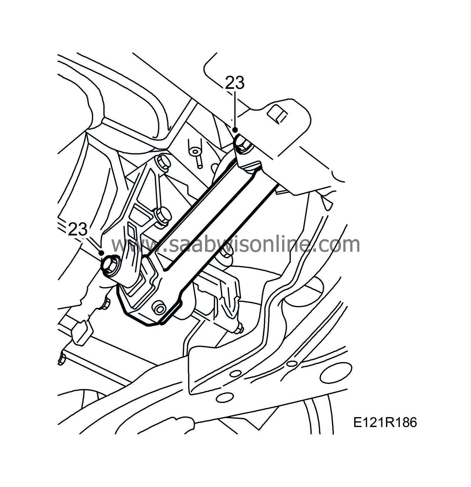
23.
|
Remove the front torque arm.
Man:
Undo the bolt on the gearbox and fold up the torque arm.
|
|
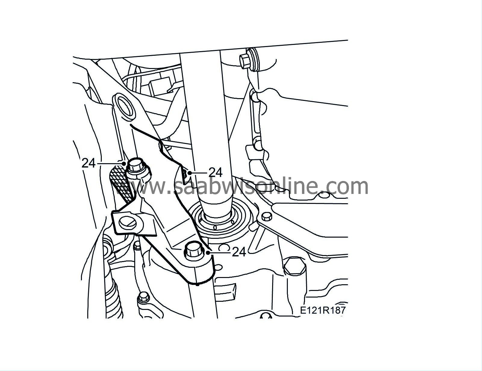
24.
|
Remove the bolts holding the rear engine mounting to the gearbox.
|
|
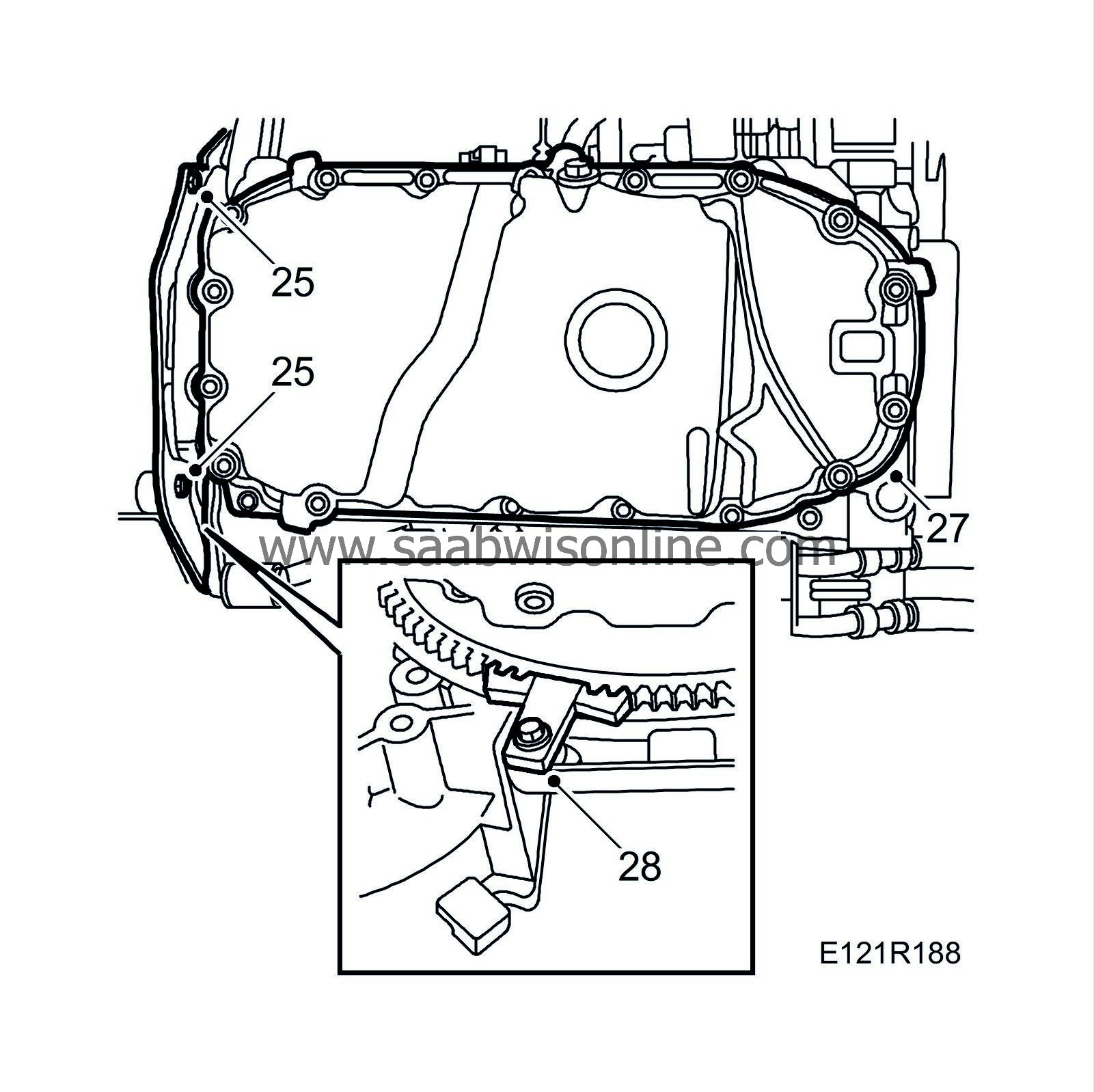
25.
|
Remove the protective cover between the engine and gearbox.
|
|
26.
|
Remove the generator's electrical connection.
|
|
27.
|
Undo the crankcase ventilation hose and remove the oil sump. Carefully prise open with a crowbar according to the illustration in order to remove the oil sump.

|
|
28.
|
Fit a 83 94 868 Flywheel locking attachment, on the starter ring gear.
|
|
29.
|
Place double 83 95 238 Wedge between the oil filter adapter and the subframe as well as between the inboard drive shaft universal joint and the subframe.
|
Note
|
|
Take care of the drive shaft universal joint gaiter.
|
|
|
31.
|
Remove the upper coolant hose from the radiator.
|
|
32.
|
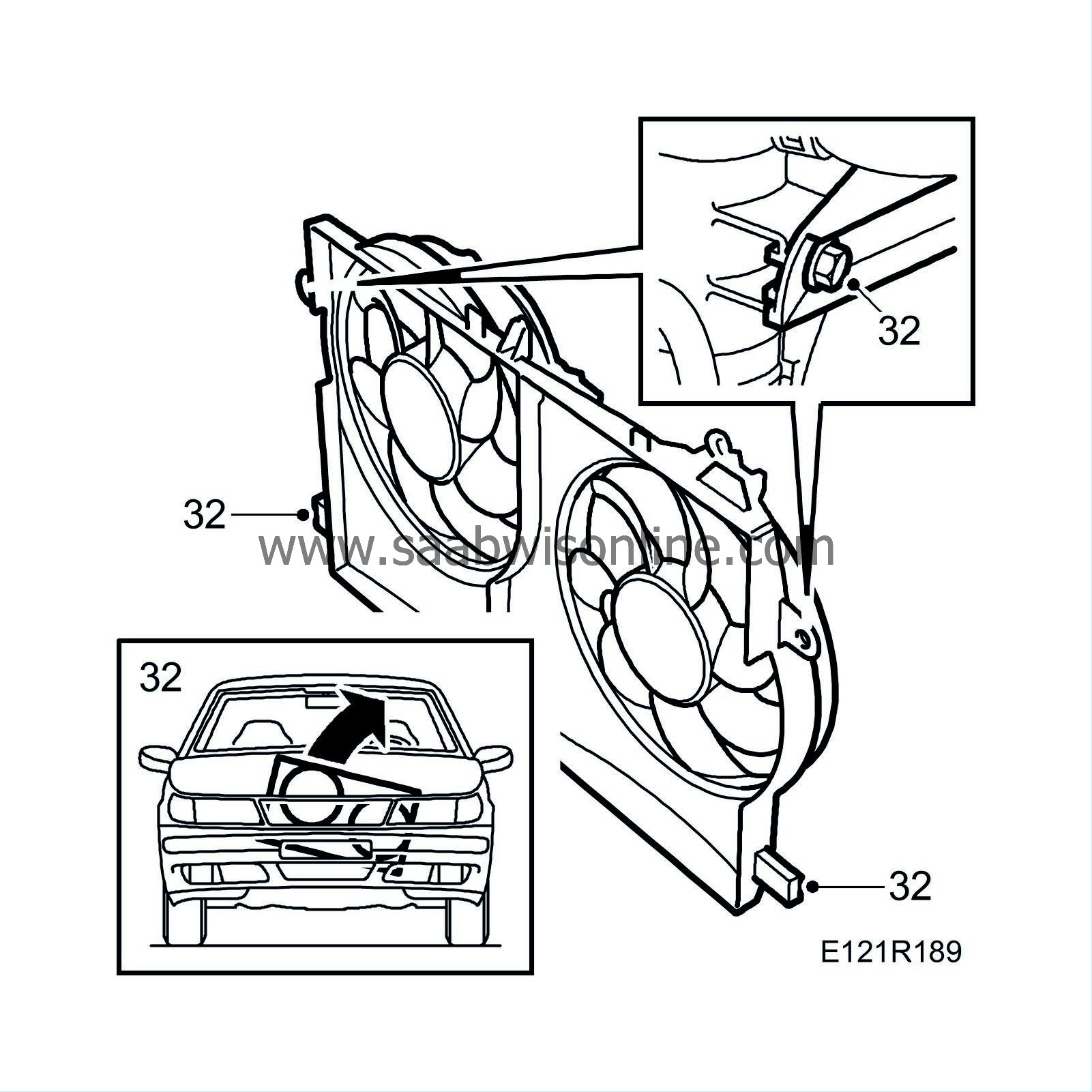
Remove the fan cowling connector and the hose clip for the expansion tank hose. Remove the fan cowling.
Aut:
Remove the bolt for the oil cooler pipe.
|
|
33.
|
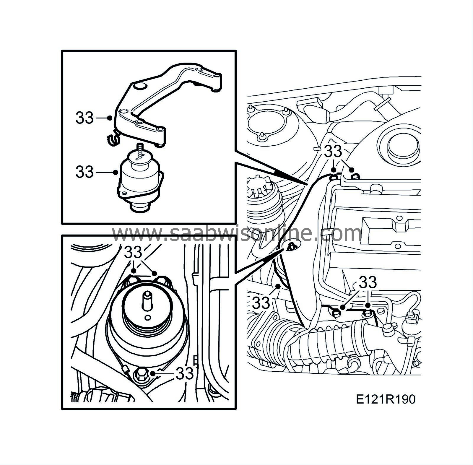
Remove the bracket to the right-hand engine mounting and the engine pad.
|
|
34.
|
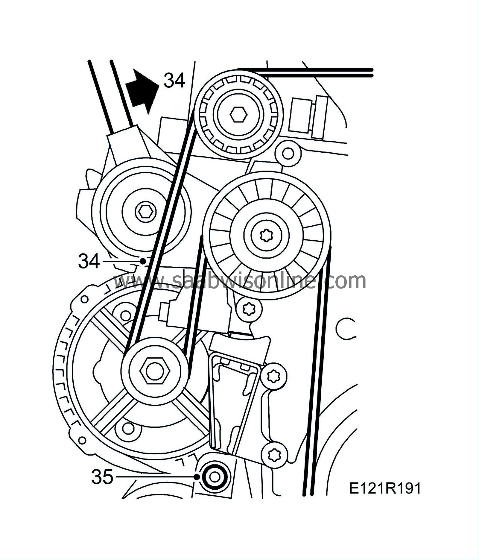
Relieve the belt tensioner and remove the multigroove belt. Mark the direction of rotation on the belt.
|
|
35.
|
Remove the generator's lower bolt and the outer lower bolt which screws into the timing cover on the intermediate shaft's bearing bracket.
|
|
36.
|
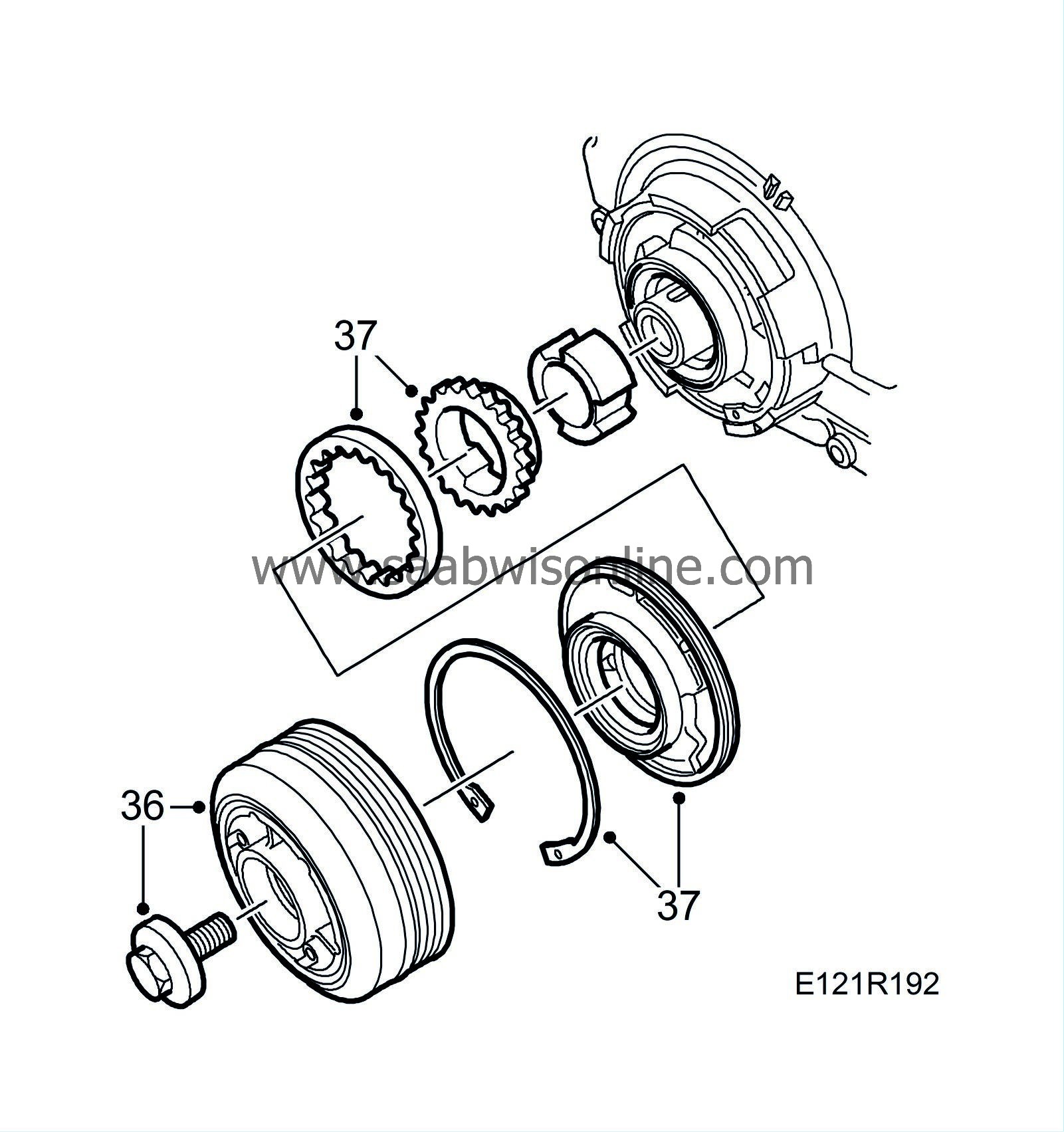
Remove the crankshaft pulley.
|
|
37.
|
Remove the oil pump. Use 82 93 086 Circlip pliers Ø120-200 mm. Retain the cover guide pins.
|
|
38.
|
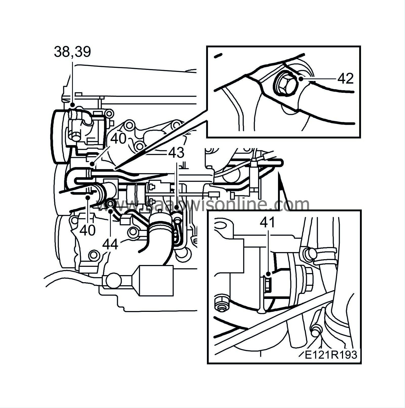
Remove the power steering pump from the mounting and move aside. Secure with a 83 95 212 Strap.
|
|
39.
|
Remove the power steering pump's mounting bracket.
|
|
40.
|
Detach the hose clips and the hoses on the coolant pump inlet.
|
|
41.
|
Remove both longitudinal coolant pipes from the cylinder block.
|
|
42.
|
Remove both coolant pipes from the coolant pump.
|
|
43.
|
Loosen the coolant pipe bolt (on the turbo) slightly from the coolant pump.
|
|
44.
|
Remove the coolant pipe from the coolant pump.
|
|
45.
|
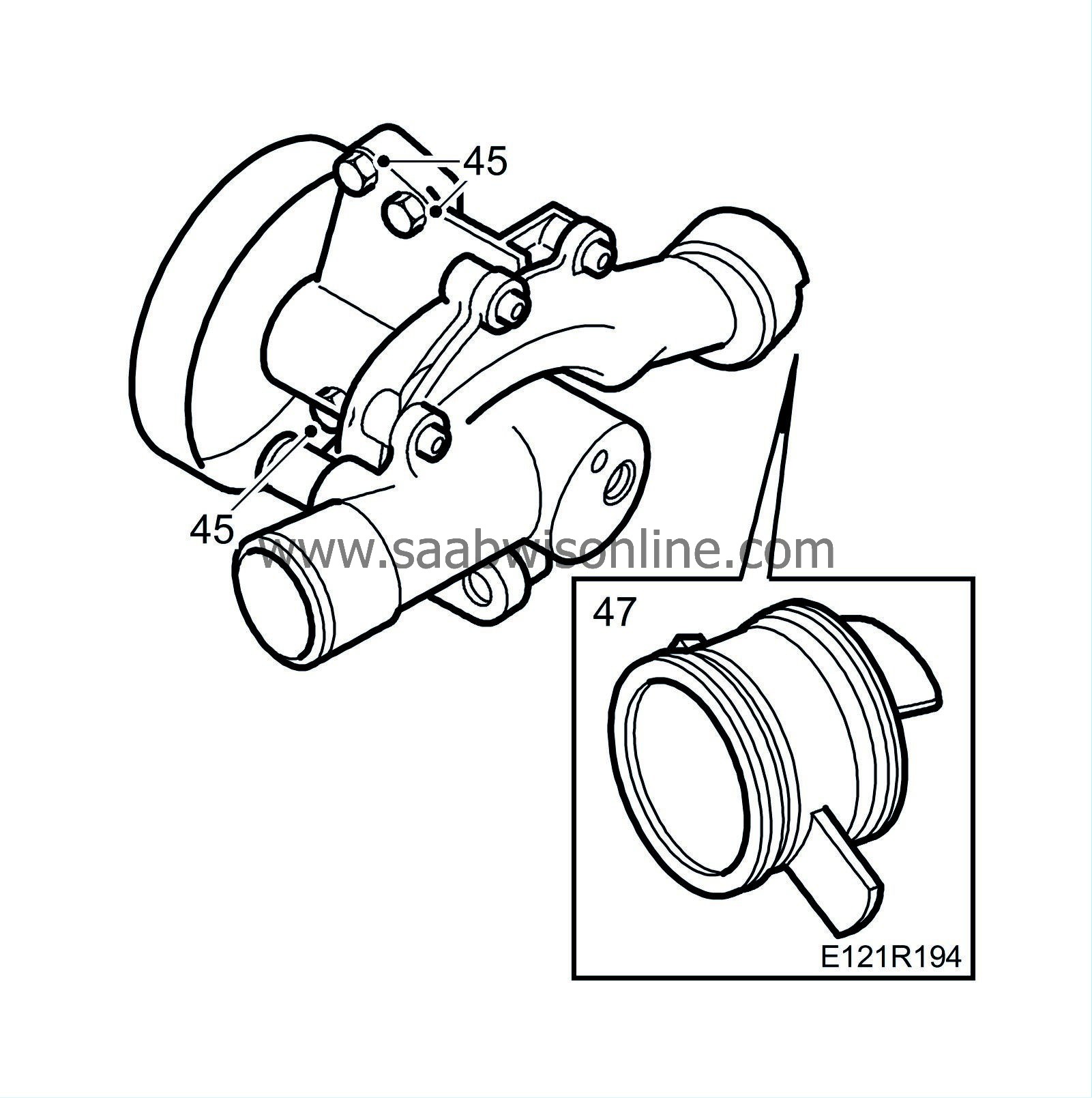
Remove the coolant pump retaining bolts.
|
|
46.
|
Carefully coax the pump away from the bracket and from the pump's connection sleeve in the cylinder block.
|
|
47.
|
Remove the connection sleeve from the cylinder block.
|
|
48.
|
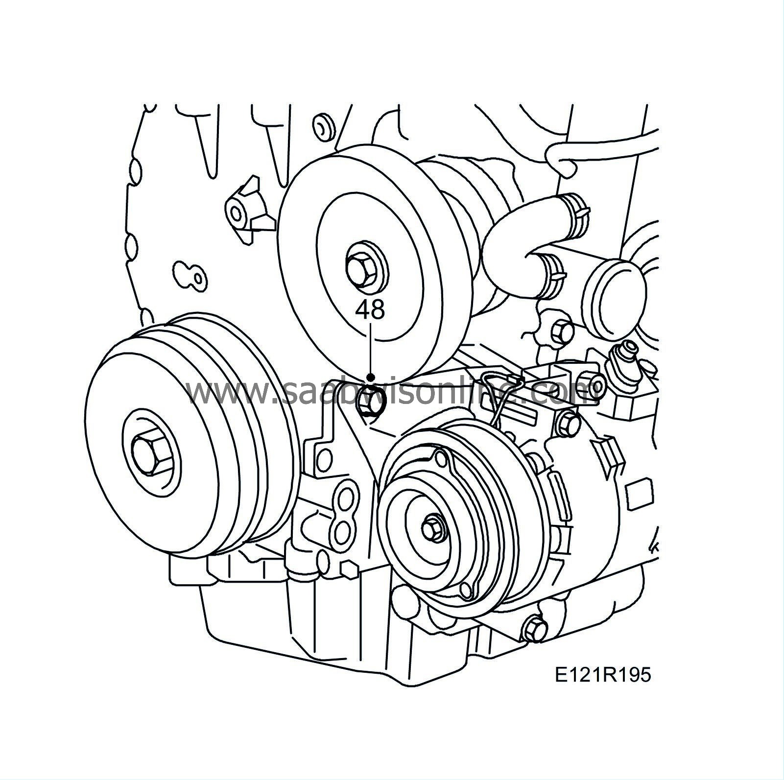
Remove the AC bracket right-hand upper bolt which screws into the timing cover.
|
|
49.
|
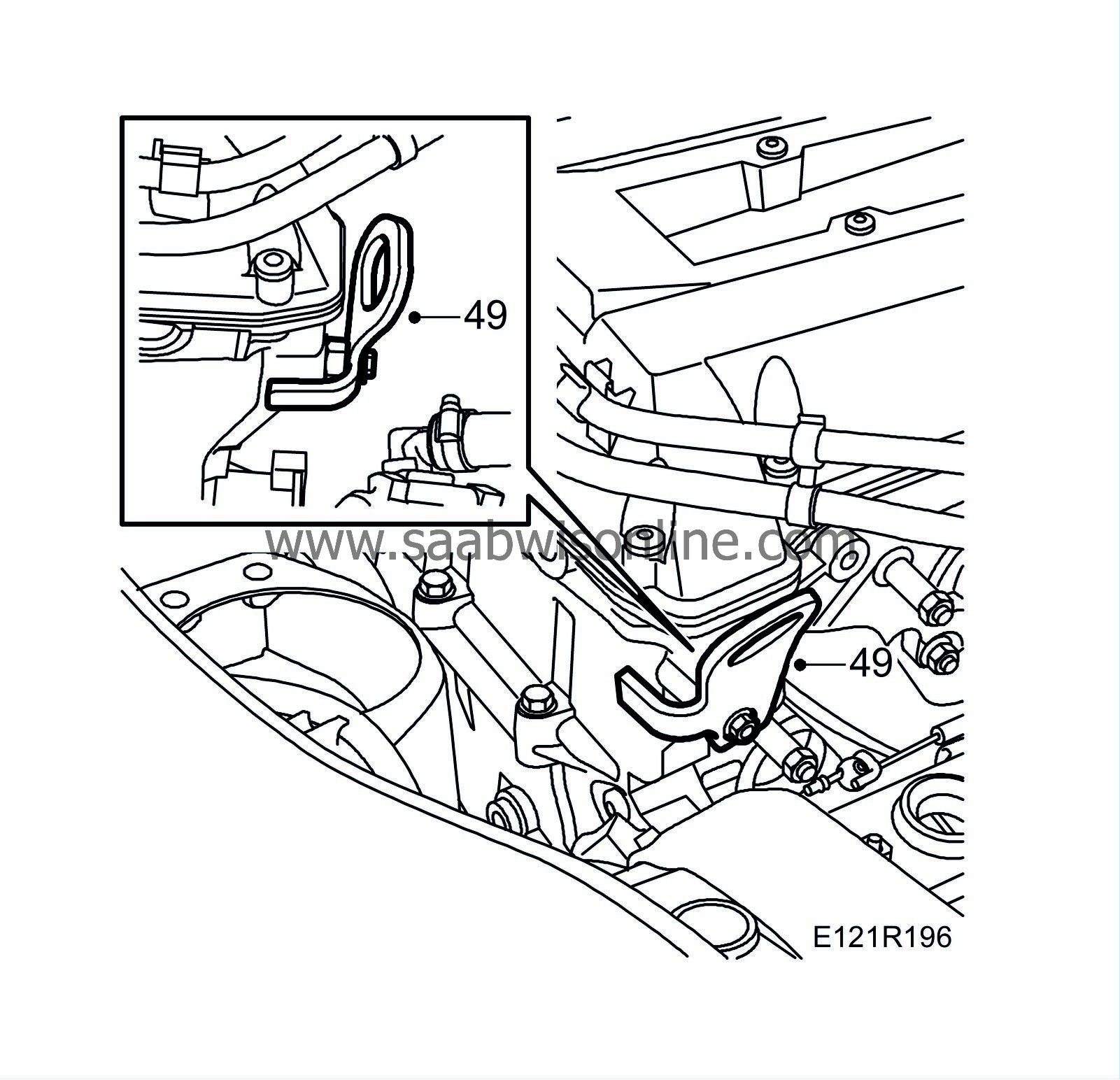
Fit 83 96 178 Lifting eyes with bolt and washers or an M12 nut between the cylinder head and bracket.
|
|
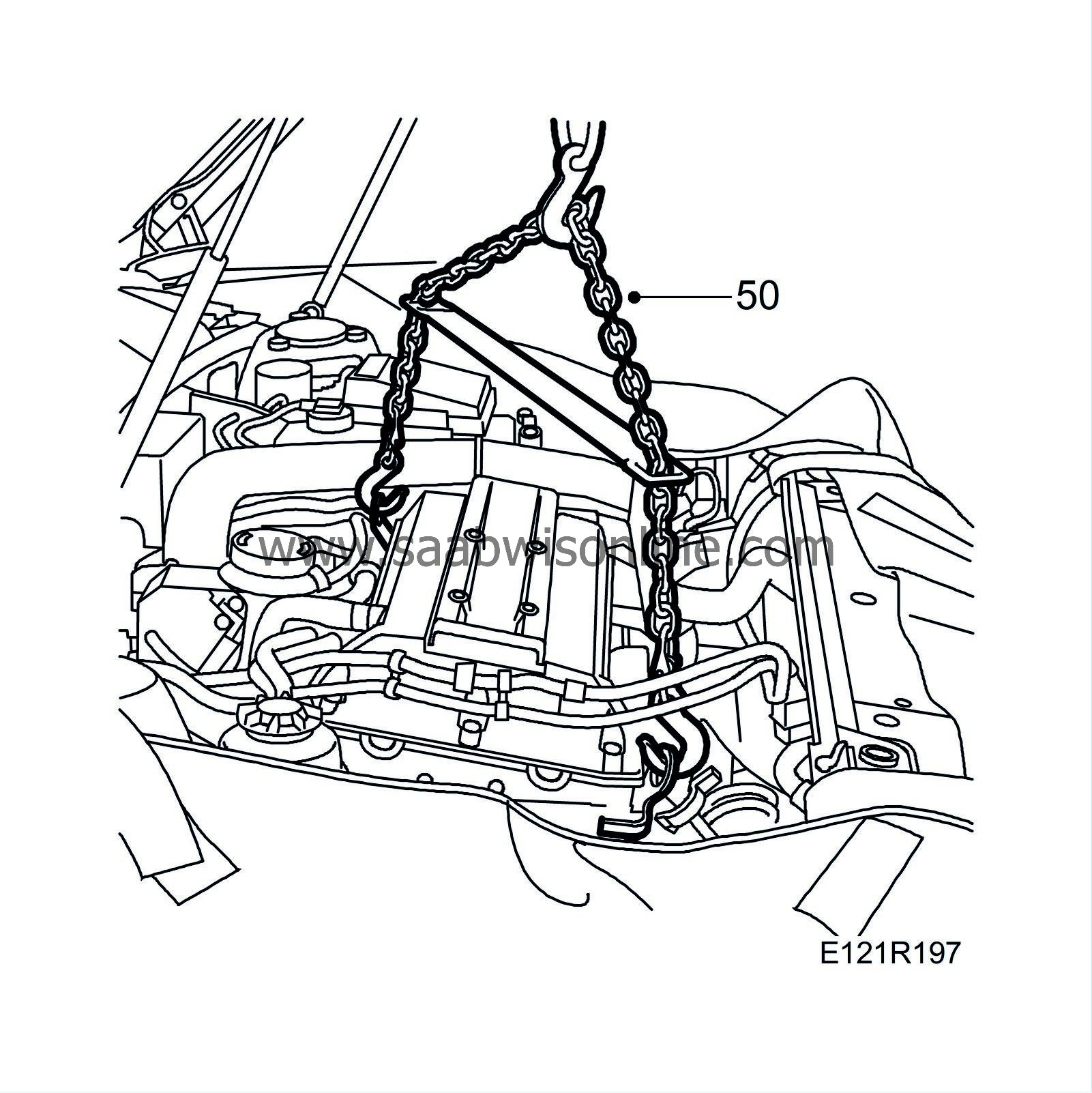
50.
|
Connect an engine lift and unload the engine from the wedges.
|
|
51.
|
Undo the electrical centre and move it aside. Secure with a 83 95 212 Strap. Take care not to scratch the paintwork.
|
|
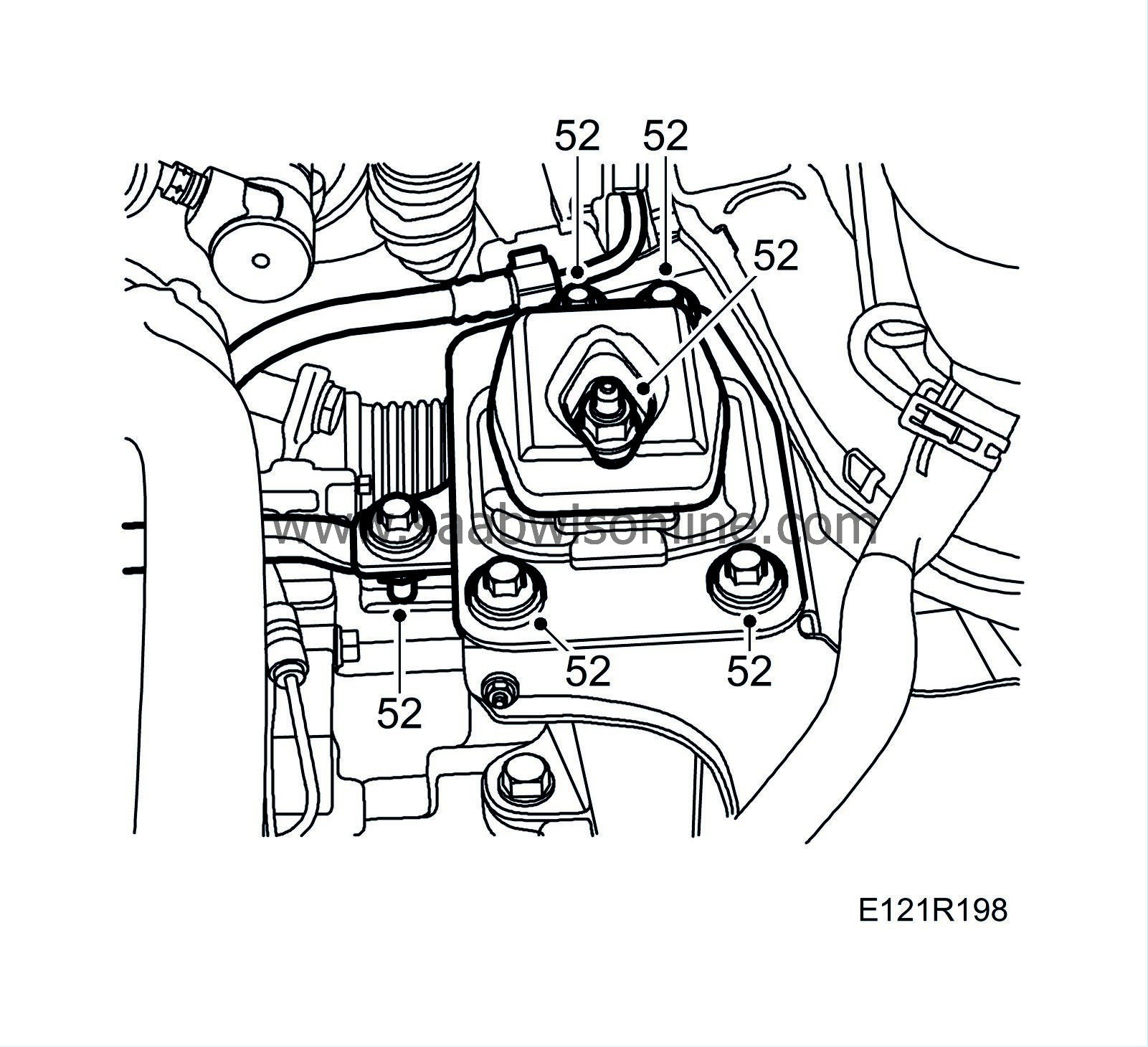
52.
|
Mark the position relative the washers and remove the left-hand engine pad.
|
Note
|
|
Note the location of the short bolt.
|
|
|
53.
|
Man:
Remove the torque rod mounting and ground cable.
|
|
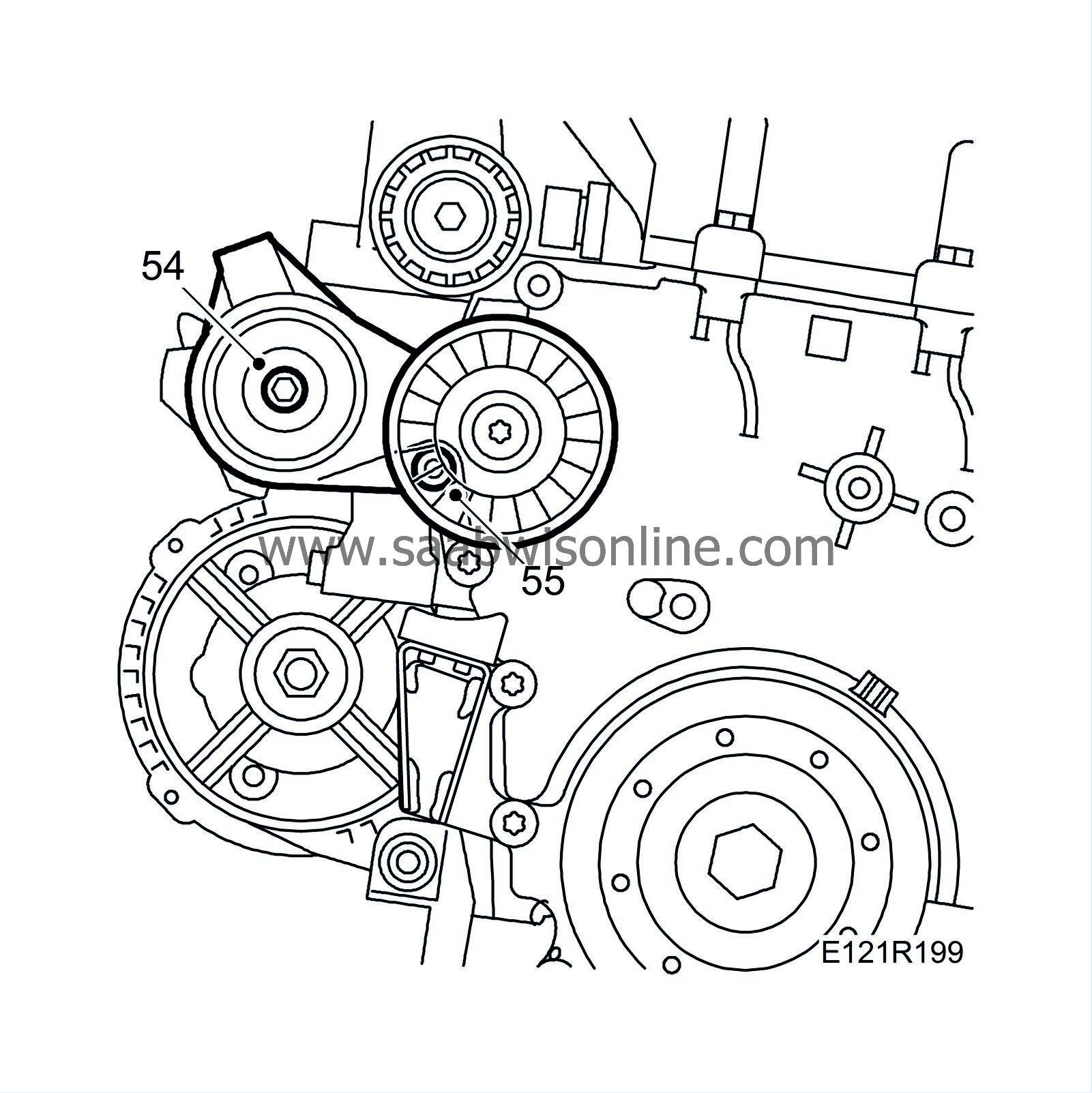
54.
|
Lift the engine slightly and remove the belt tensioner.
|
|
55.
|
Remove the upper generator retaining bolt and remove the generator.
|
|
56.
|
Remove the generator bracket.
|
|
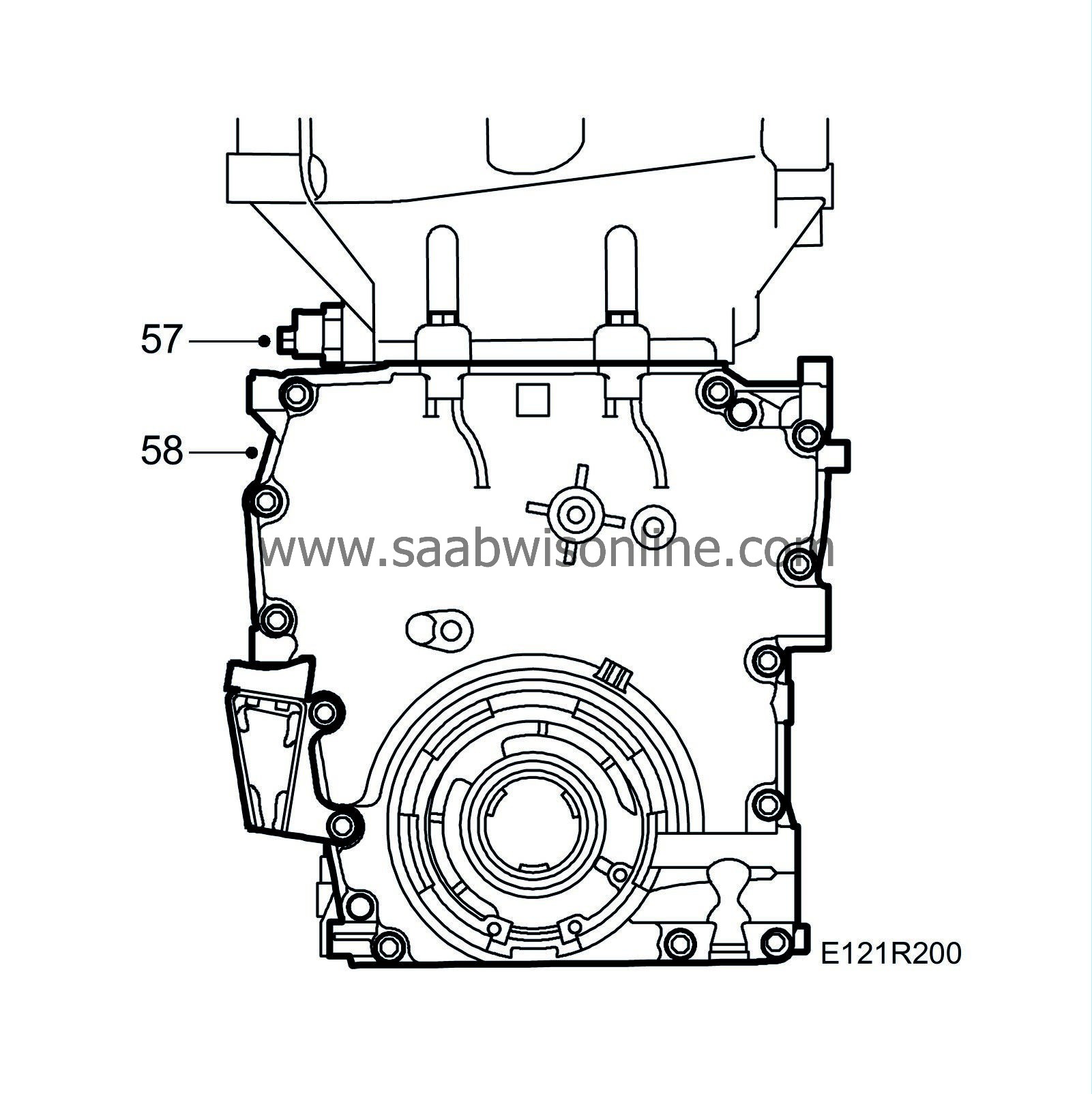
57.
|
Remove the timing cover bolts. Move the engine to the left. Raise and lower the engine respectively to gain access to all the bolts. Use a ratchet handle and a Torx 40 bit.
|
|
58.
|
Remove the timing cover from below. Move the engine to the left. Use a pry bar and place a wood block between the pry bar and the cylinder head. Raise and lower respectively to remove the cover. Protect the paintwork with fabric tape. Two people are needed.
|
Note
|
|
Take care of the cylinder head gasket.
|
|
|
59.
|
Remove the plug for the chain tensioner and the chain tensioner. Take care of the spring and pin.
|
|
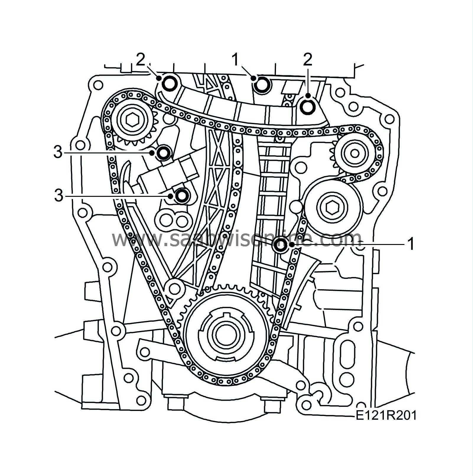
1.
|
Undo each bolt for the fixed balancer shaft and timing chain guides separately and replace with the new bolt. Tighten each bolt before undoing the next one.
Tightening torque 10 Nm (7 lbf ft).
|
|
2.
|
Undo each bolt for the upper balancer shaft chain guide separately and replace with the new bolt. Tighten each bolt before undoing the next one.
Tightening torque 10 Nm (7 lbf ft).
|
|
3.
|
Remove the balancer shaft chain tensioner
|
|
4.
|
Check that the chain tensioner piston is in the correct position. If the piston can be fully pushed in then it is aligned incorrectly and must be turned 180
°
.
|
|
5.
|
Turn the piston on the balancer shaft chain's chain tensioner 90
°
, press it in and turn back 90
°
. Secure the tensioner with a wire clip or similar in the hole on the top side of the tensioner.
|
|
6.
|
Fit the chain tensioner and remove the wire clip.
Tightening torque 10 Nm (7 lbf ft)
|
|
7.
|
Fit the timing chain tensioner.
Tightening torque 63 Nm (46 lbf ft)
|
|
8.
|
Fit the pin, the spring and the plug to the chain tensioner.
Tightening torque 22 Nm (16 lbf ft)
|
|
9.
|
Clean any remaining sealant from the timing cover sealing surfaces. Use the recommended degreasing agent.
|
|
10.
|
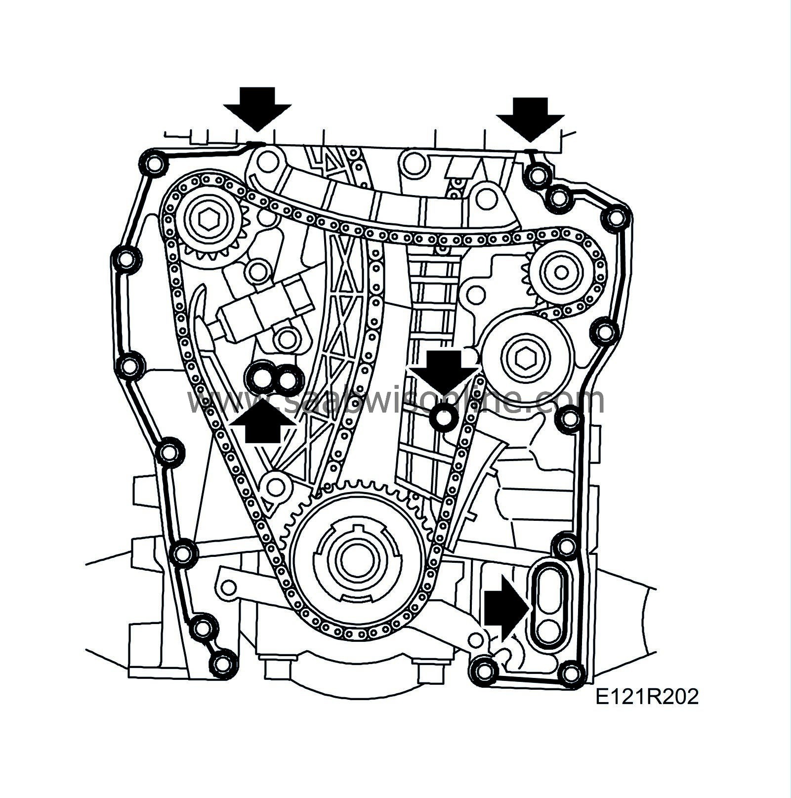
Apply a bead of 90 297 970 Flange sealant about 2 mm thick along the middle of the sealing surfaces and around the bolt hole and oilways as illustrated or apply the flange sealant to the corresponding surfaces on the timing cover. Dab a small amount of 83 95 691 Silicone flange sealant in the joints between the cylinder head and the cylinder block.
|
|
11.
|
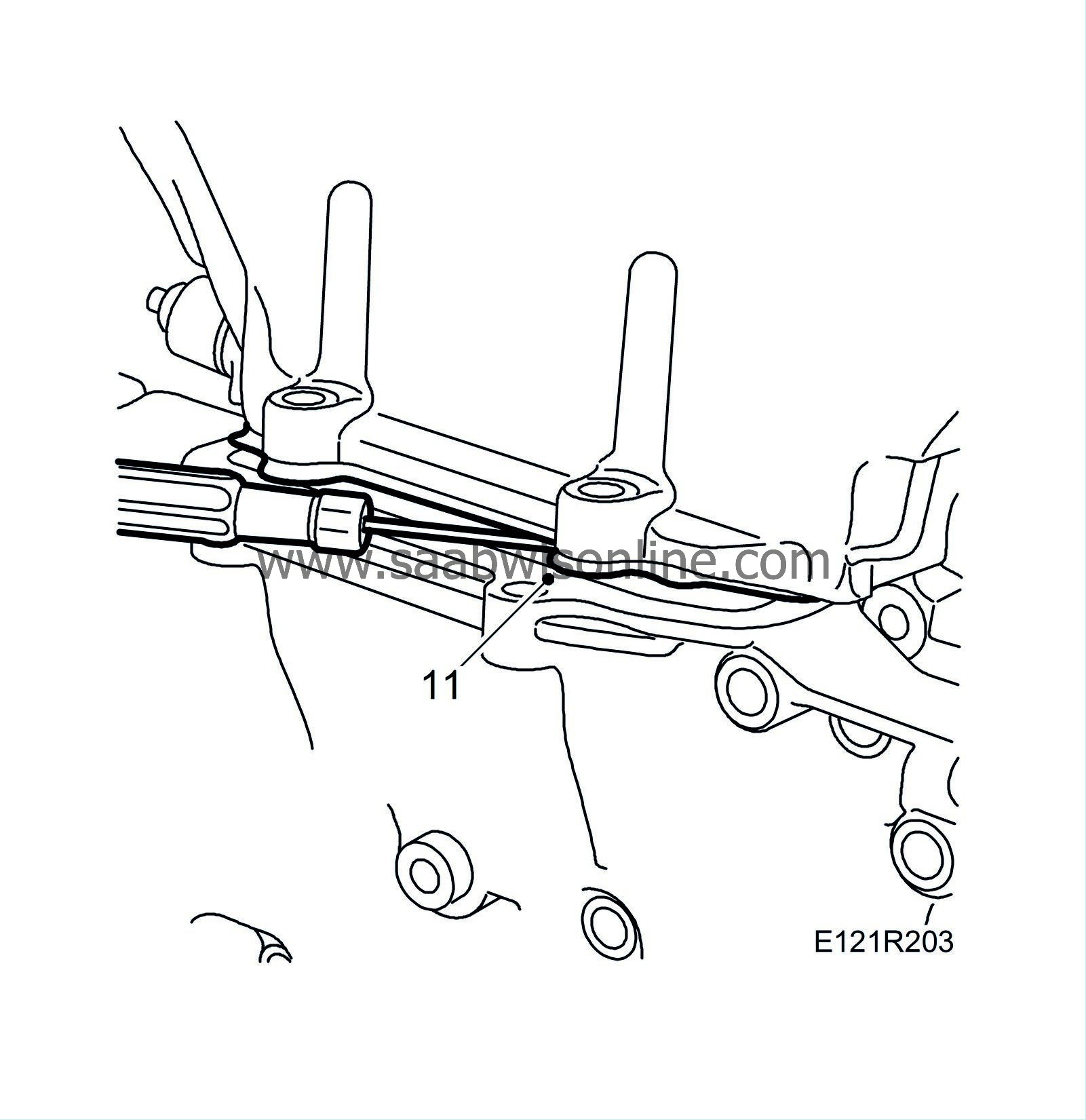
Fit the timing cover by carefully twisting it in place. Use a pry bar and place a wood block between the bar and the cylinder head. Move the engine to the left and raise and lower respectively to fit the timing cover and the bolts.
|
Note
|
|
Make sure the cover does not catch on the cylinder head gasket. Move the gasket away with a screwdriver or feeler gauge.
|
Tightening torque 22 Nm (16 lbf ft)
|
|
12.
|
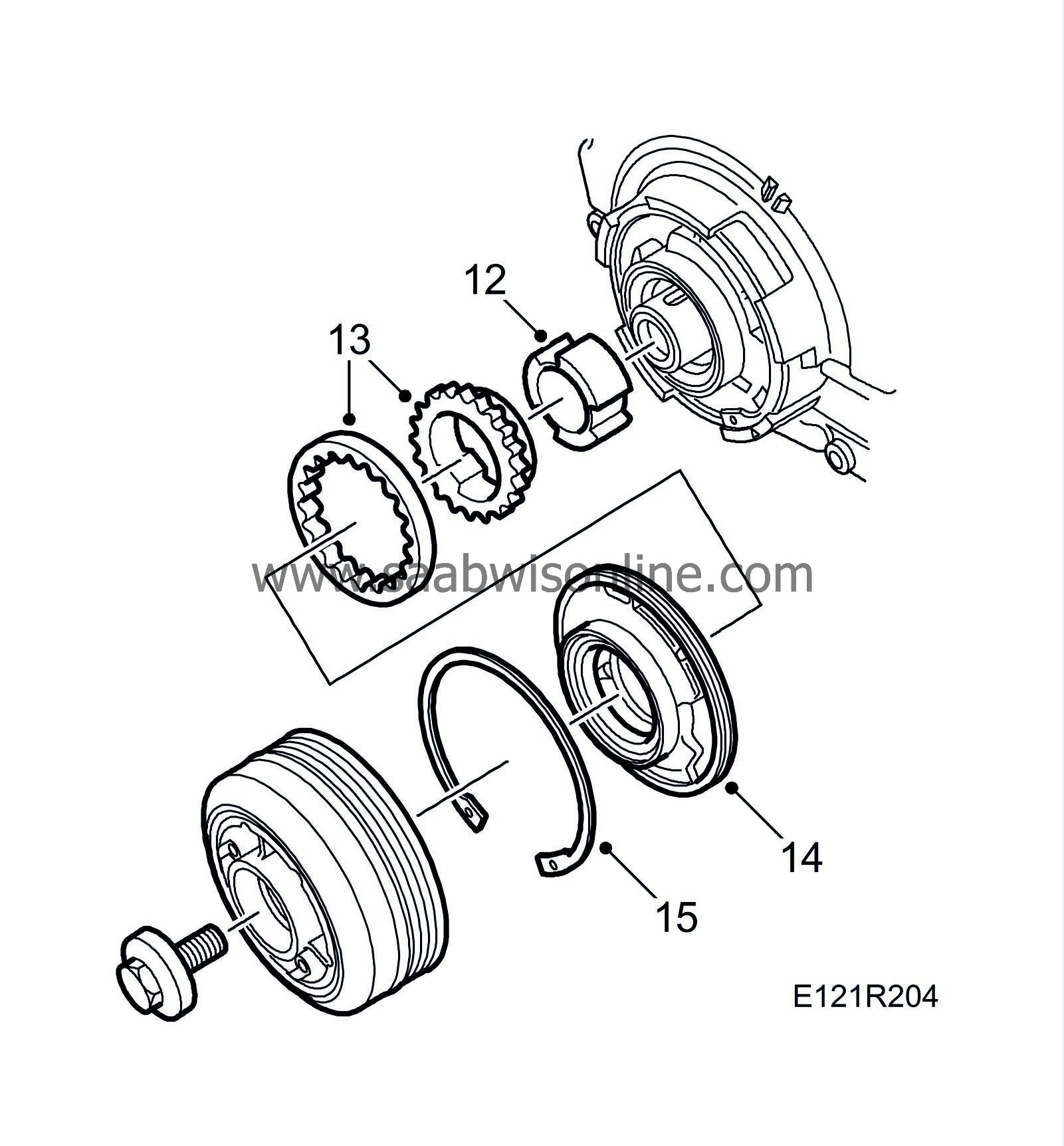
Fit the oil pump driver.
|
|
13.
|
Make sure that the marking on the oil pump gear ring is turned outward and pump impeller with flange inward. Use a new O-ring, grease with Vaseline.
|
|
14.
|
Oil and fit the pump impellers and fit the pump cover in the correct position using the guide arrows and guide pin.
|
|
15.
|
Fit the circlip with the bevelled edge face out and the opening pointing down.
|
|
16.
|
Fit the bolt to the intermediate shaft's bearing bracket.
Tightening torque 22 Nm (16 lbf ft)
|
|
17.
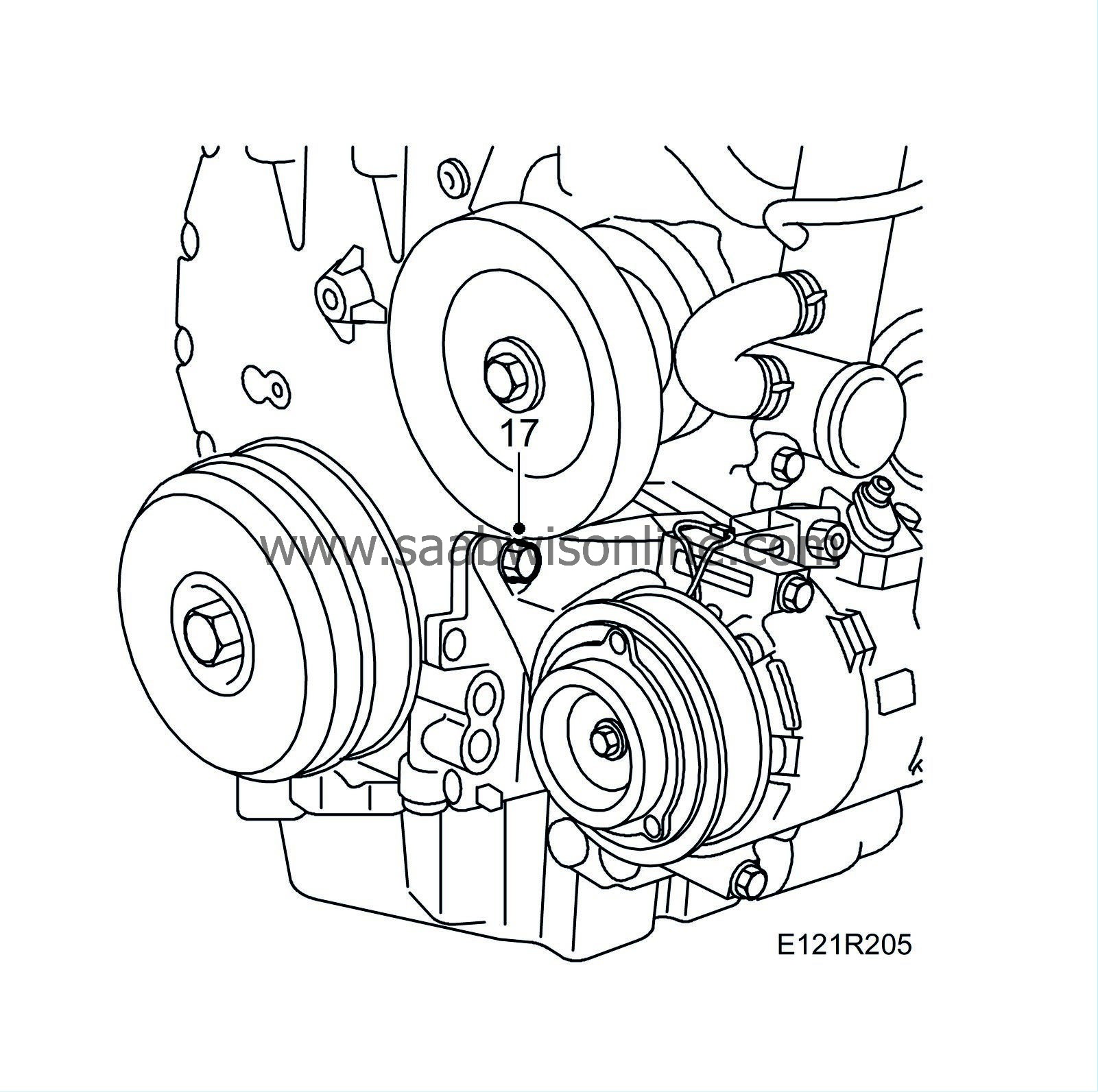
|
Fit the bolt to the AC compressor bracket.
Tightening torque 40 Nm (30 lbf ft)
|
|
18.
|
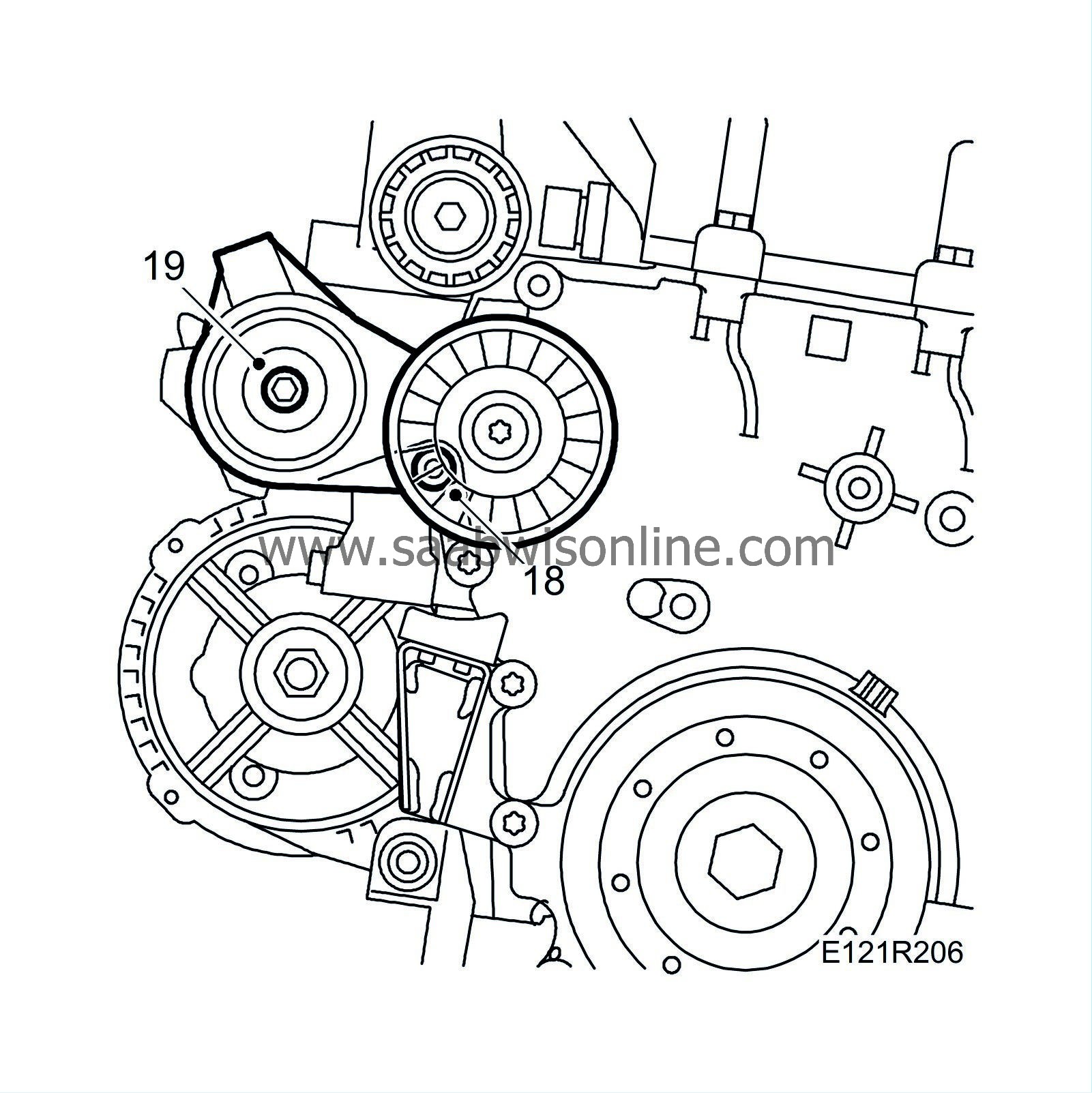
Press out the generator adjuster sleeve slightly and fit the generator mounting and the generator.
Tightening torque, generator 47 Nm (35 lbf ft)
Tightening torque, generator bracket 24 Nm (18 lbf ft)
|
|
19.
|
Fit the belt tensioner.
Tightening torque 59 Nm (44 lbf ft)
|
|
20.
|
Man:
Fit the torque rod mounting and ground cable.
Tightening torque 47 Nm (35 lbf ft)
|
|
21.
|
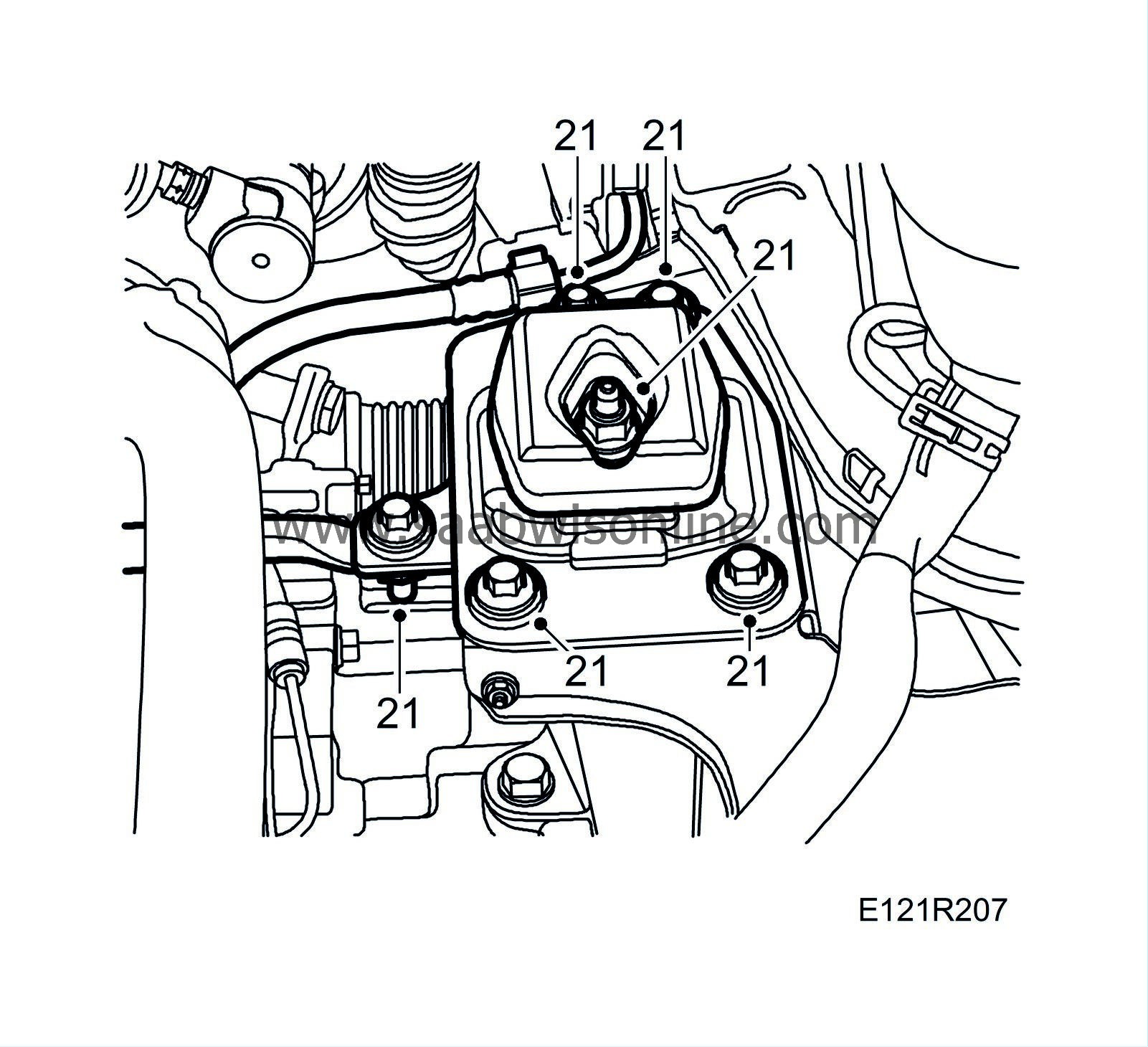
Fit the left-hand engine pad. Centre the engine pad on the marks made earlier.
Tightening torque, bolts 40 Nm +45
°
(35 lbf ft +45
°
)
Tightening torque, nut 84 Nm (62 lbf ft)
|
|
22.
|
Fit the electrical centre
|
|
23.
|
Lower the engine on the wedges at the oil filter adapter and the drive shaft universal joint. Remove the lifting eye
|
|
24.
|
Fit the crankshaft pulley.
Tightening torque 175 Nm (129 lbf ft)
|
|
25.
|
Clean any coolant spilled on the A/C compressor bracket.
|
|
26.
|
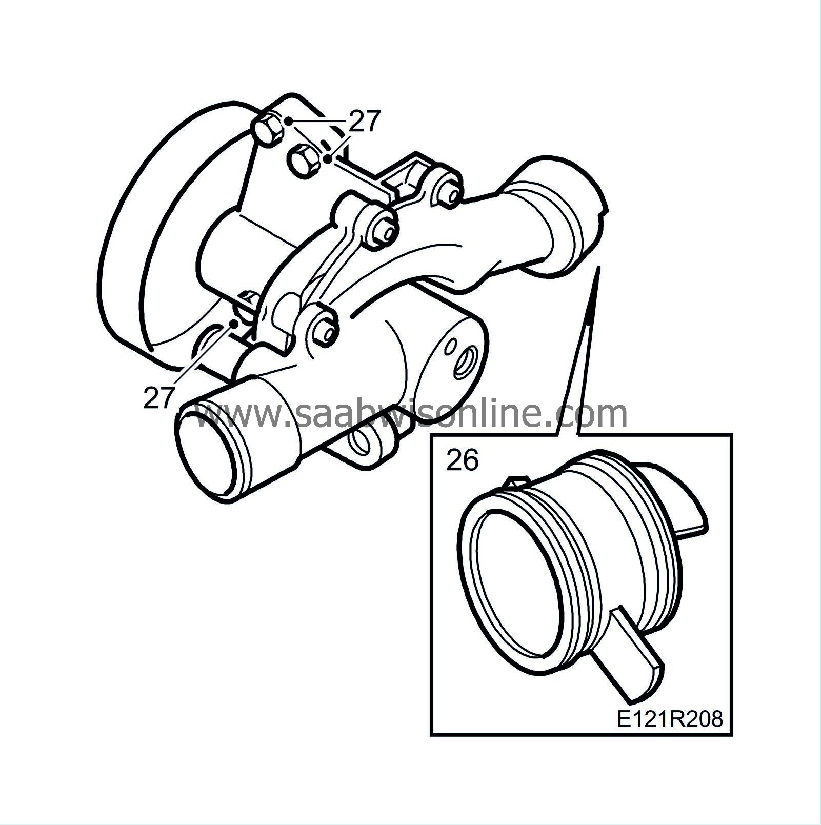
Apply non-acidic Vaseline on the seals and fit the connection sleeve to the cylinder block. Clean the seat in the cylinder block.
|
|
27.
|
Fit the coolant pump.
Tightening torque 22 Nm (16 lbf ft)
|
|
28.
|
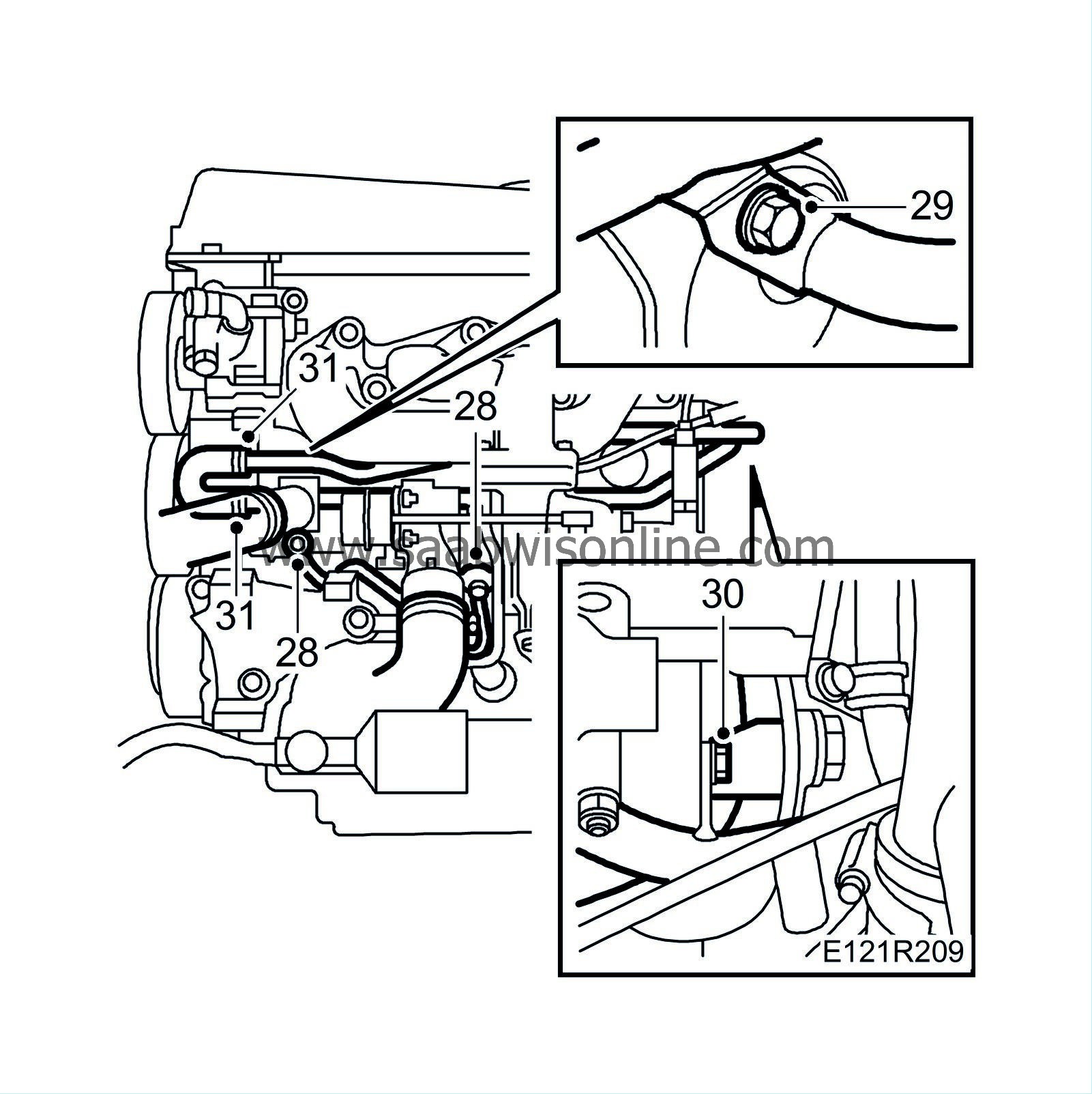
Fit the coolant pipe on the coolant pump and on the turbo. Use new seals.
Tightening torque, banjo screw, turbocharger 25 Nm (18 lbf ft)
Tightening torque, banjo screw, coolant pump 20 Nm (15 lbf ft)
|
|
29.
|
Fit both the longitudinal coolant pipes to the coolant pump with a new O-ring.
Tightening torque 10 Nm (7 lbf ft).
|
|
30.
|
Fit both longitudinal coolant pipes to the cylinder block.
|
|
31.
|
Fit the hose clips and the hoses on the coolant pump inlet.
|
|
32.
|
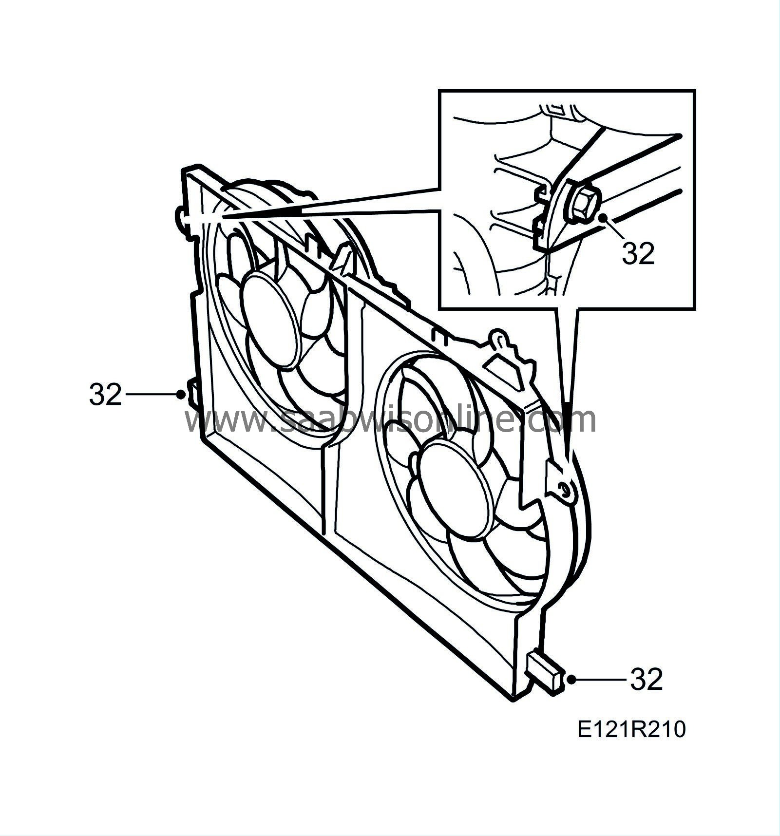
Fit the fan cowling. Attach the connector and hose clips. Fit the upper coolant hose.
Aut:
Fit the bolt for the oil cooler pipe.
|
|
33.
|
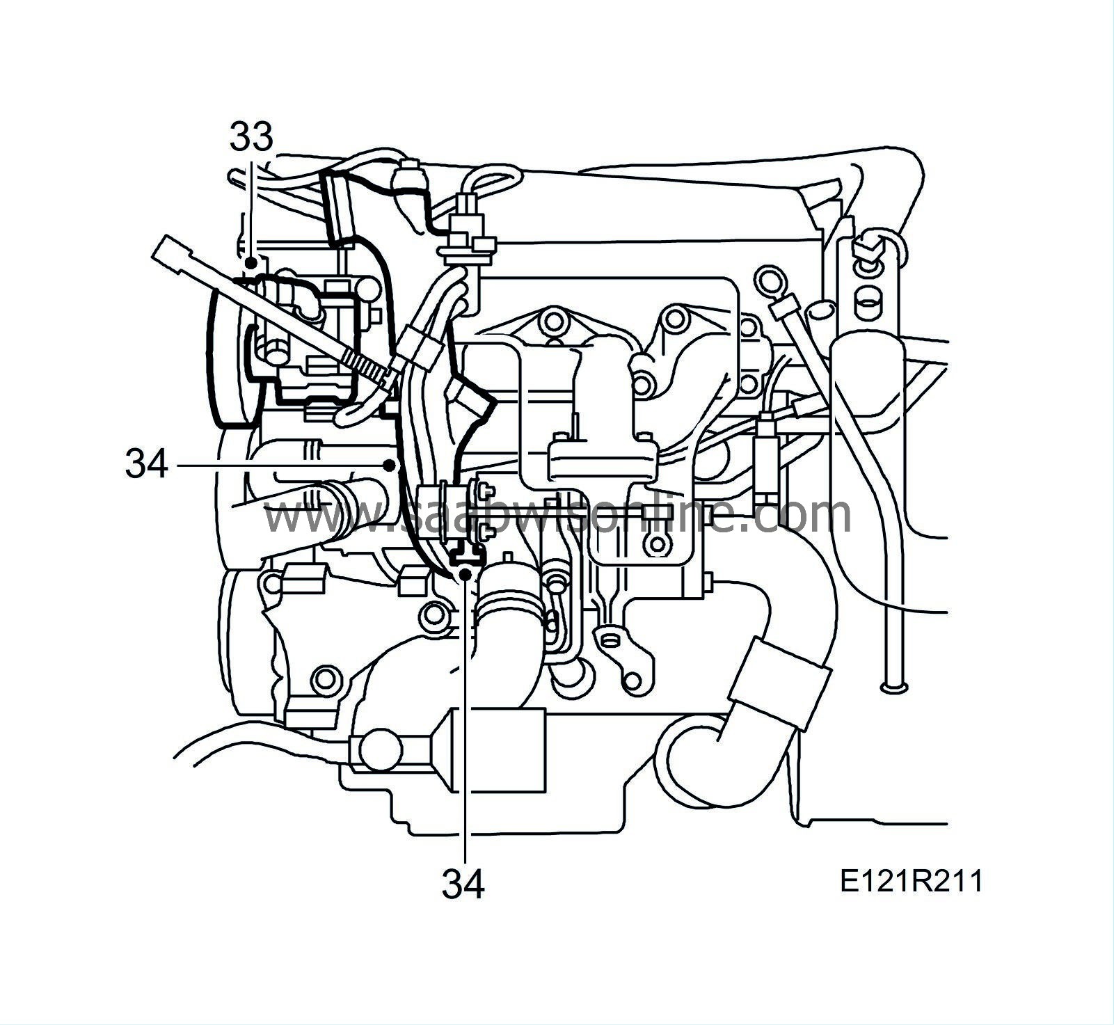
Fit the bracket for the power steering pump and the power steering pump.
Tightening torque 24 Nm (18 lbf ft)
|
|
34.
|
Fit the turbocharger delivery pipe hose to the turbo intake pipe and fit the intake manifold to the turbo with a new O-ring.
|
|
35.
|
Fit the engine's lifting eye.
|
|
36.
|
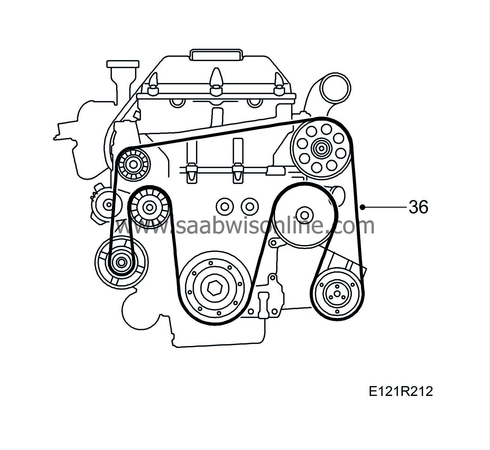
Fit the poly-V-belt in accordance with the indicated rotation direction.
|
|
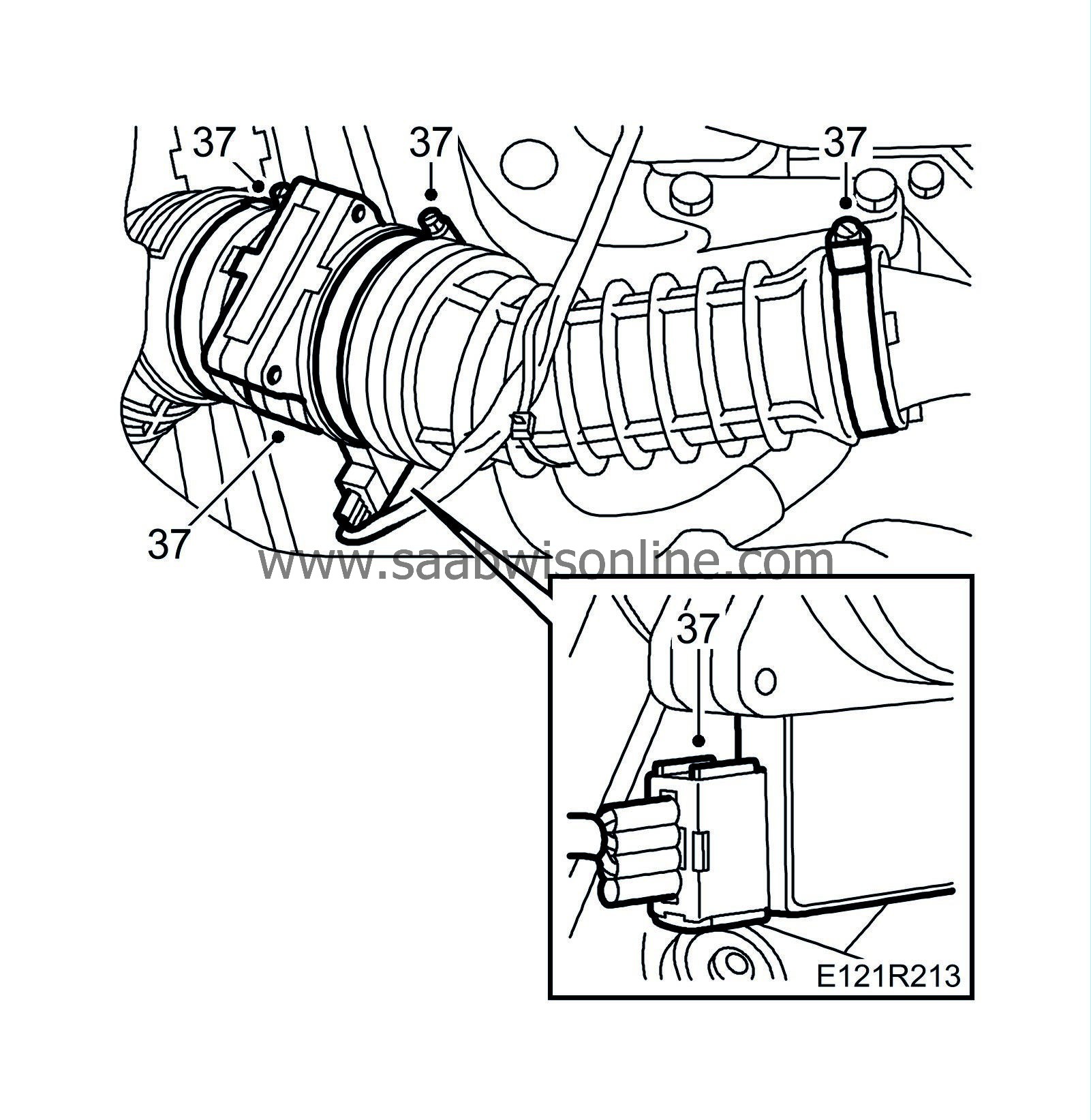
37.
|
Fit the mass air flow sensor with hose and connector.
|
|
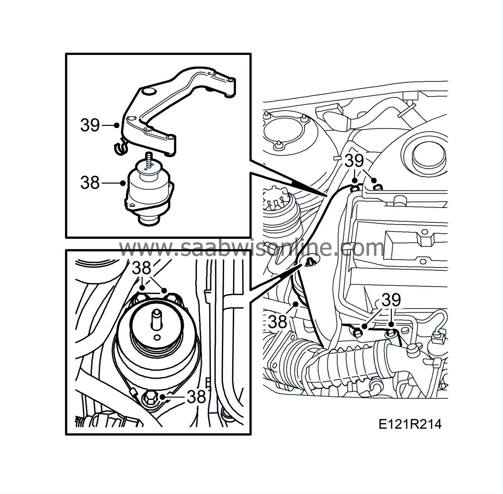
38.
|
Fit the right-hand engine mounting.
Tightening torque 47 Nm (35 lbf ft)
|
|
39.
|
Fit the engine mounting bracket. Do not fit the nut yet.
Tightening torque, bolts 47 Nm (36 lbf ft)
|
|
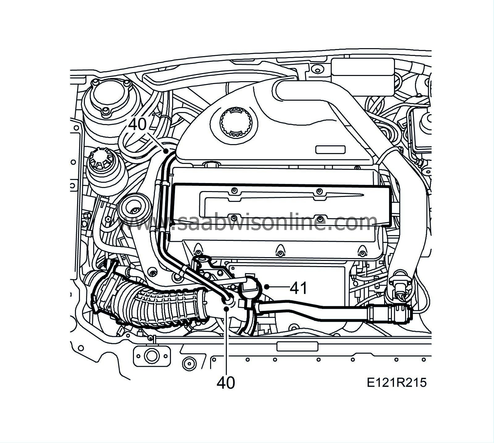
40.
|
Fit the crankcase ventilation pipe.
|
|
41.
|
Fit the connector to the turbo solenoid valve.
|
|
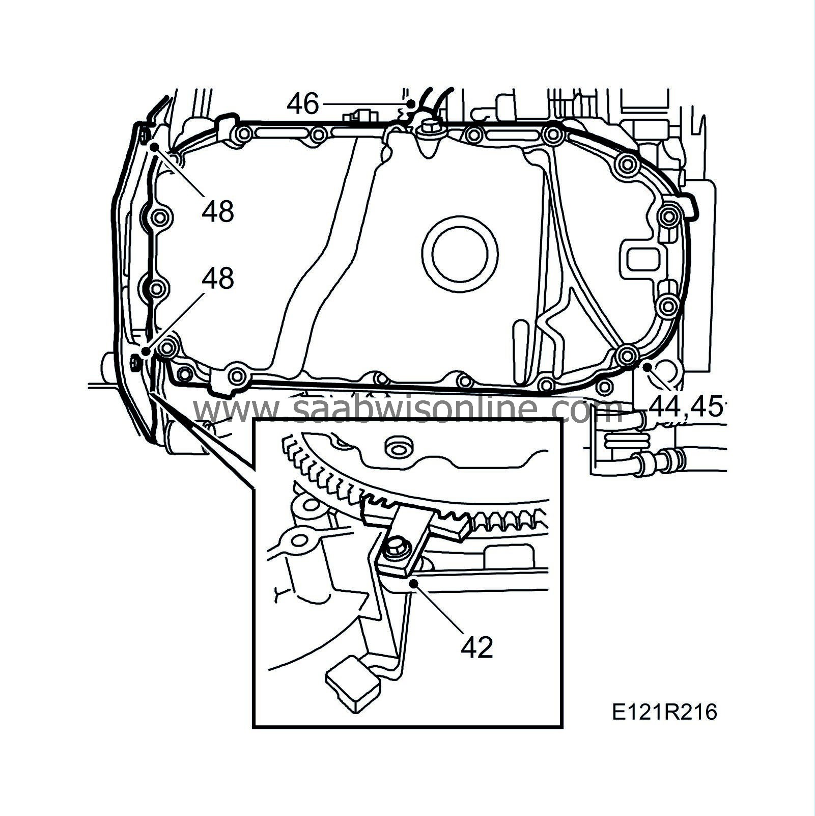
42.
|
Raise the car and remove the flywheel locking attachment.
|
|
43.
|
Clean and degrease the sealing surfaces and apply an even bead of 90 297 970 Flange sealant about 2 mm thick on the oil sump sealing surface.
|
|
44.
|
Make sure the pipe to the oil adapter is fitted securely and that it is aligned correctly in the oil sump. Fit the oil sump.
|
|
45.
|
Tighten the oil sump bolts.
Tightening torque 22 Nm (16 lbf ft)
|
|
46.
|
Fit the hose to the crankcase ventilation.
|
|
47.
|
Fit the generator's electrical connections
|
|
48.
|
Fit the protective cover to the gearbox.
|
|
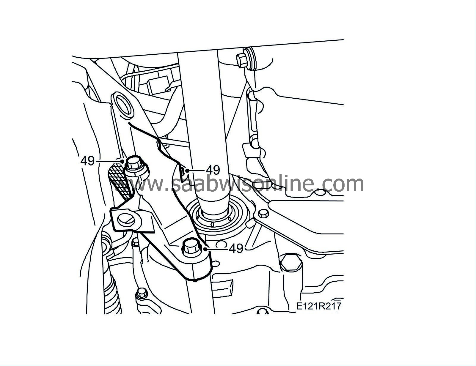
49.
|
Fit the rear engine mounting to the gearbox.
Tightening torque 60 Nm + 60° (44 lbf ft +60°)
|
|
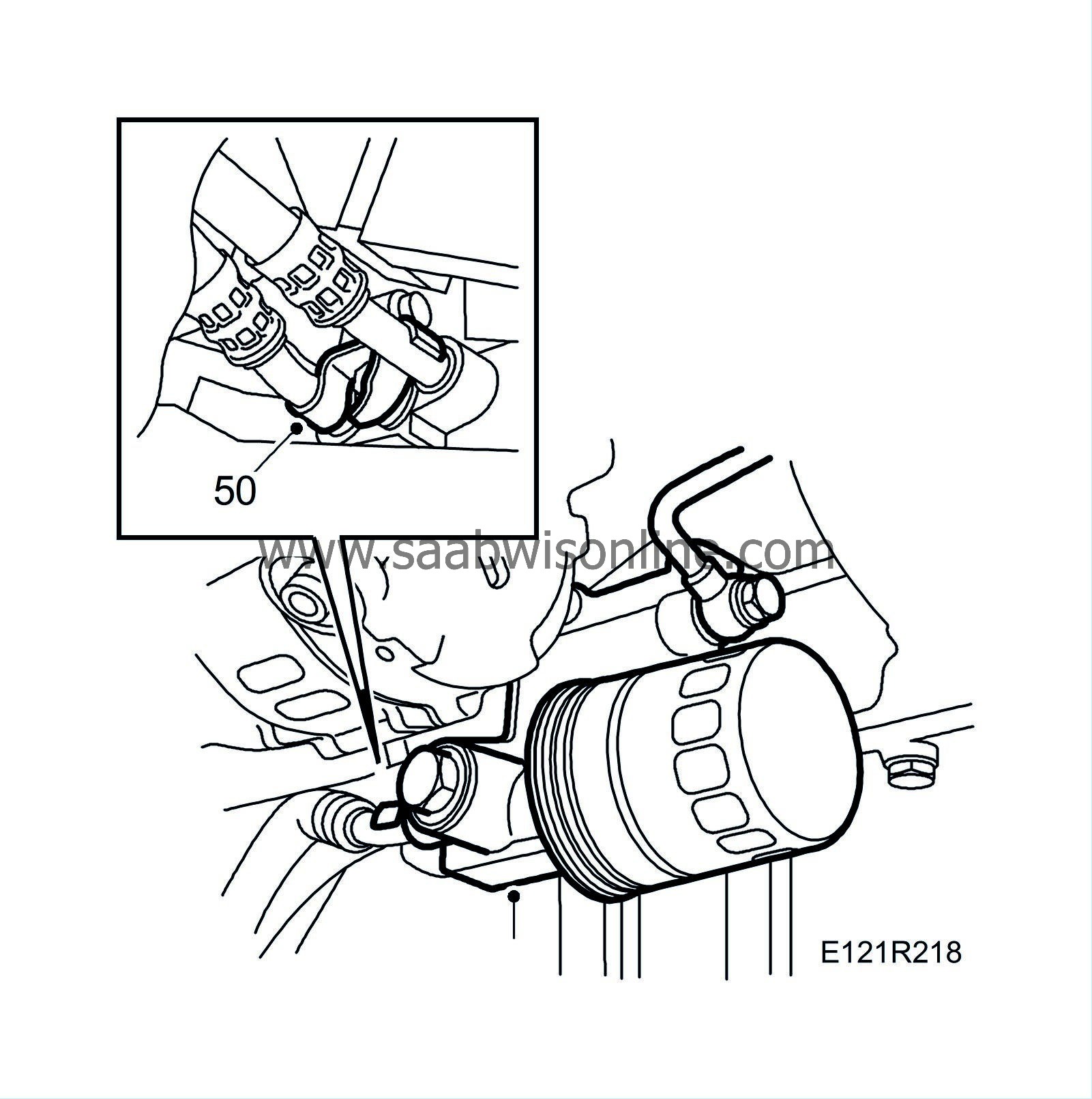
50.
|
Connect the oil pipe with new O-rings.
|
|
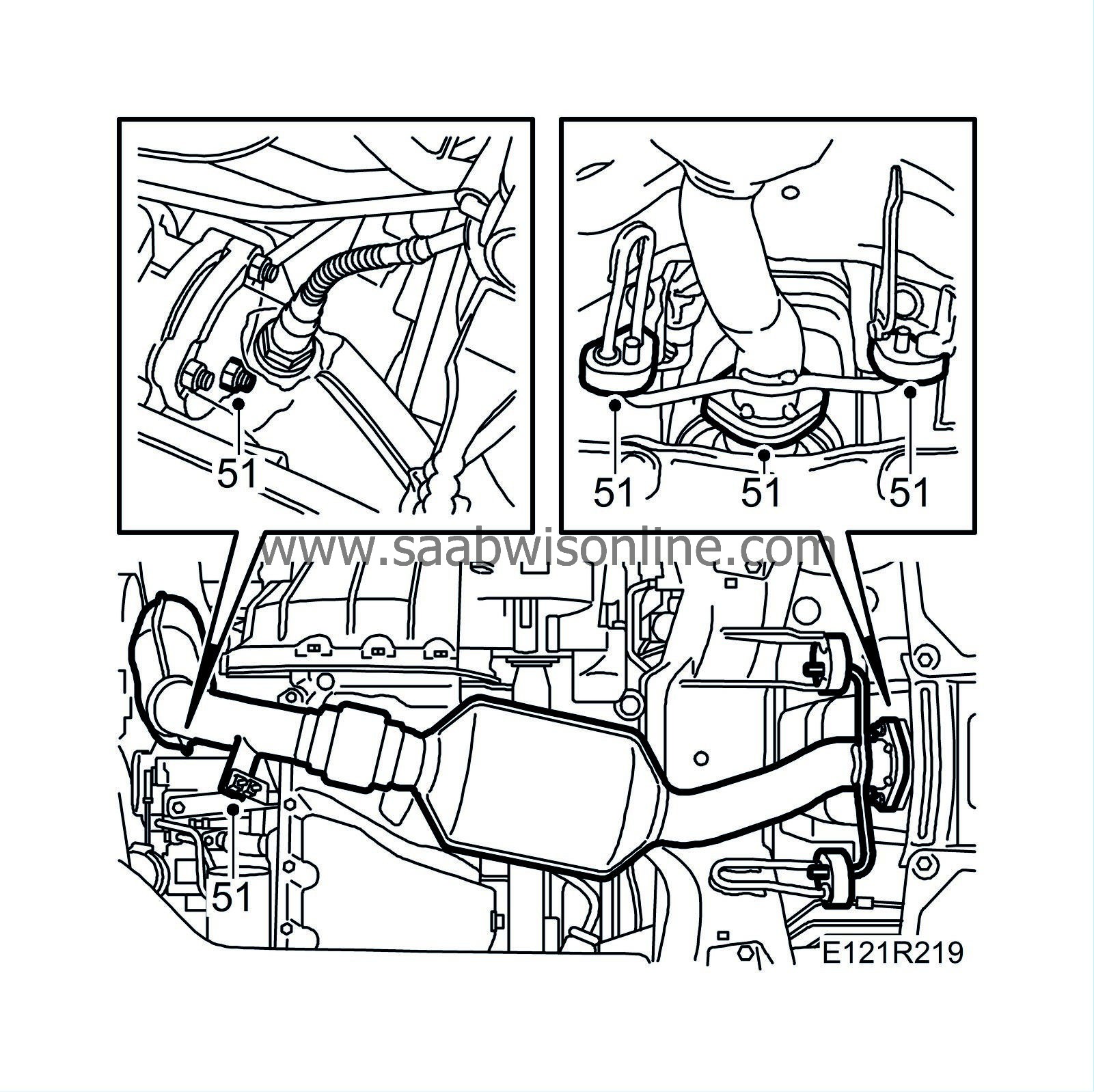
51.
|
Fit the front exhaust pipe to the turbo with new nuts. Lubricate with 90 513 210 Universal paste.
Tightening torque 22 Nm (16 lbf ft)
|
|
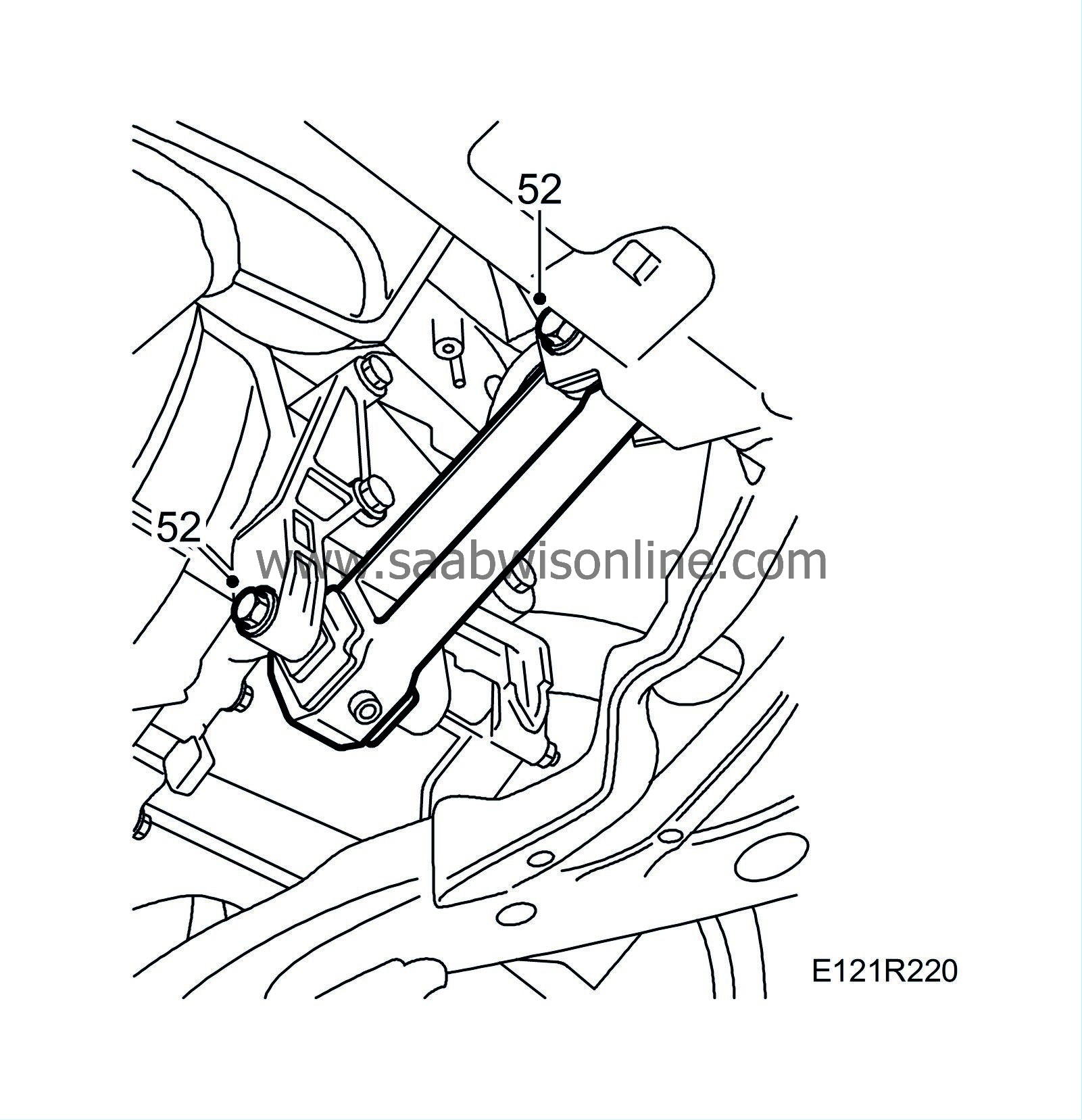
52.
|
Fit the torque arm.
Tightening torque, lead-through bolt 90 Nm + 90
°
(66 lbf ft + 90
°
)
Tightening torque, bracket 70 Nm + 90
°
(52 lbf ft + 90
°
)
|
|
53.
|
Lower the car and fit the washer and nut on the right-hand engine pad.
Tightening torque 105 Nm (78 lbf ft)
|
|
54.
|
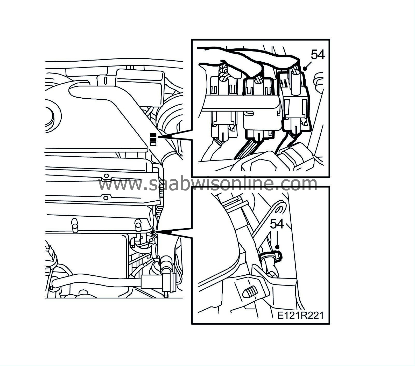
Fit and tighten the nuts on the exhaust pipe flange and plug in the oxygen sensors. Fasten the cable with cable ties.
Tightening torque 22 Nm (16 lbf ft)
|
|
55.
|
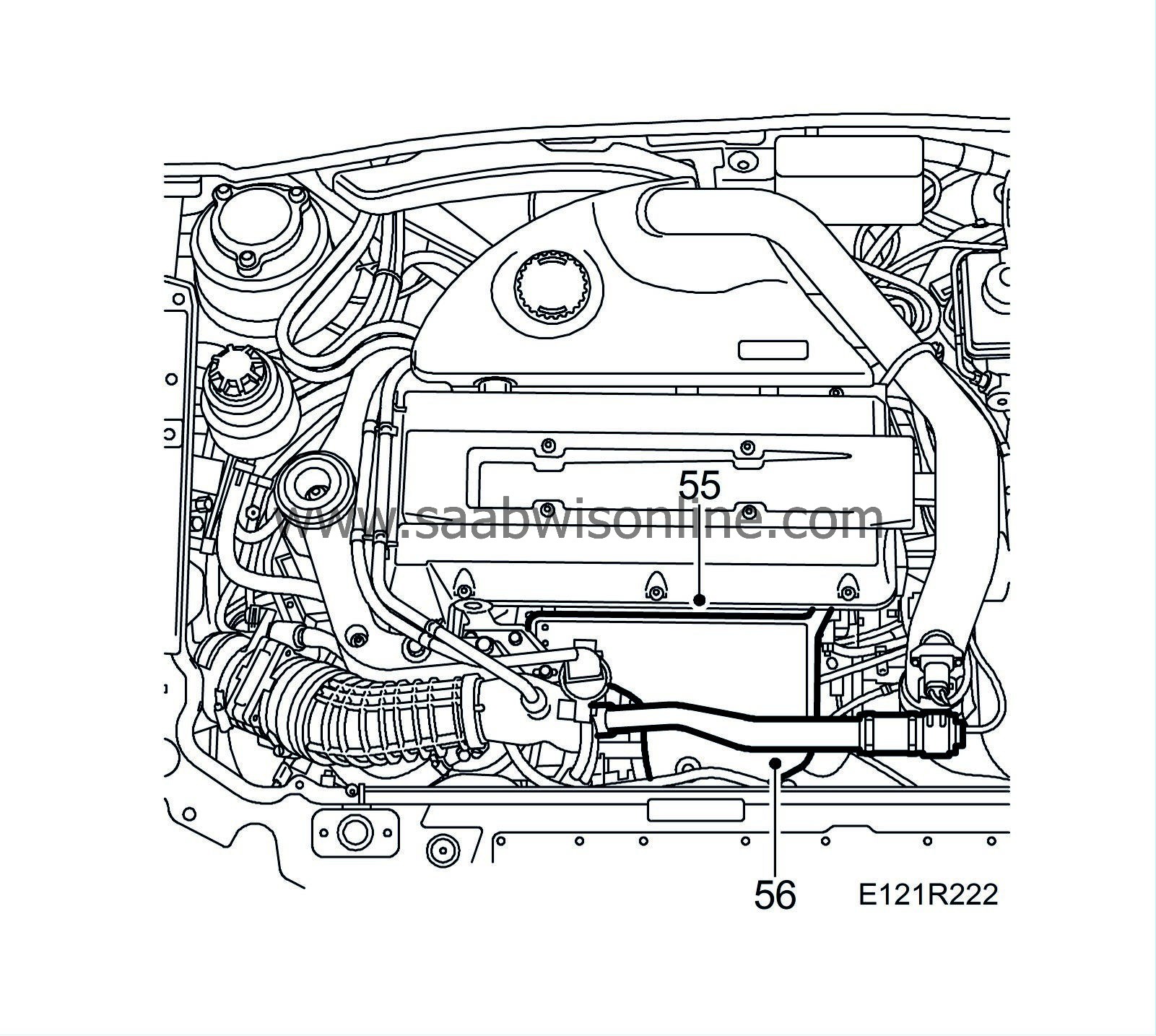
Fit the turbocharger heat shield.
|
|
56.
|
Fit the by-pass valve with pipe.
|
|
57.
|
Man:
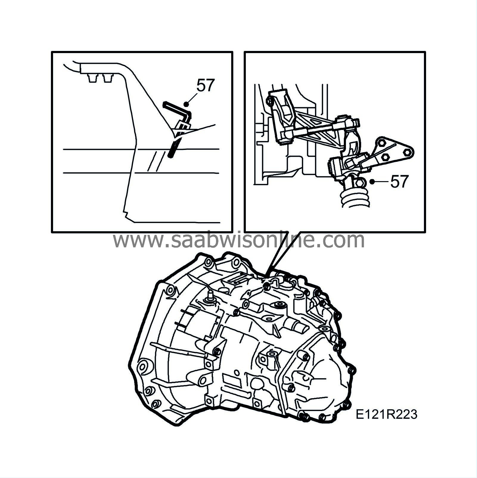
Connect the gear linkage to the selector rod.
|
|
58.
|
Man:
Undo the gear lever gaiter with frame from the centre console. Engage 4th gear and insert 87 92 632 lock pin into the gear lever housing. Tighten the clamp on the gear linkage.
Tightening torque 22 Nm (16 lbf ft)
|
|
59.
|
Man:
Remove the lock pins, check the gear positions and that the ignition key can be removed. Insert the plastic plug into the gearbox. Fit the gear lever gaiter.
|
|
60.
|
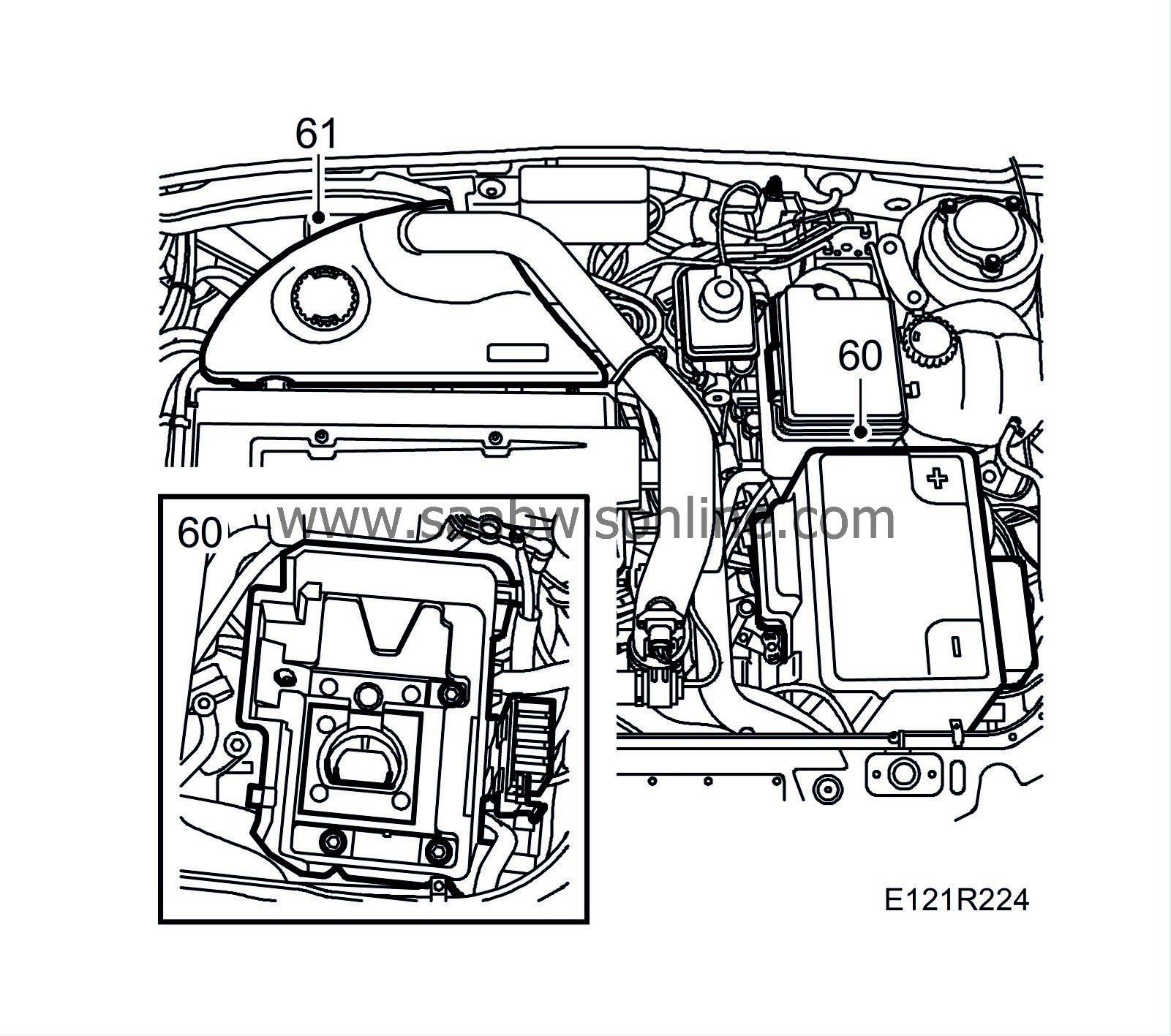
Fit the battery tray and the battery. Fit the battery cover. Connect the battery cables.
|
|
61.
|
Fit the upper engine cover.
|
|
62.
|
Raise the car and fit the spoiler shield.
|
|
63.
|
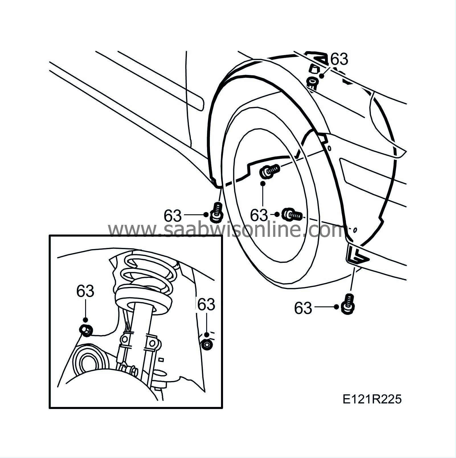
Fit the right-hand wing liner.
|
|
64.
|
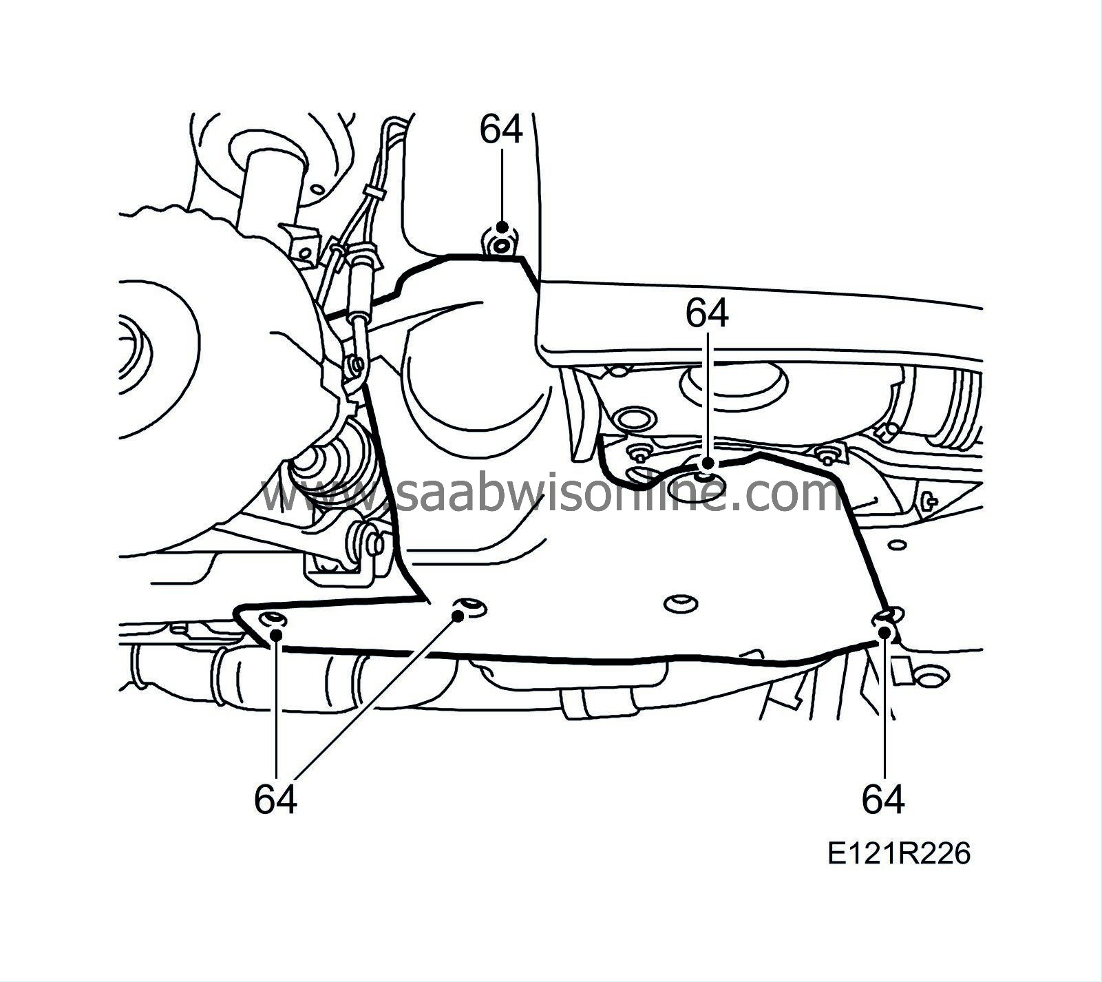
Fit the headlamp position sensor (option). Fit the drive belt cover.
|
|
65.
|
Fit the right-hand wheel. See WIS - Wheels and tyres - Wheels.
Tightening torque 110 Nm (81 lbf ft)
|
|
66.
|
Pressure test the cooling system.
|
|
67.
|
Fill with new coolant and close the expansion tank cap.
|
|
68.
|
Fill with engine oil.
|
|
69.
|
Set the car's clock and date.
|
|
70.
|
Calibrate the AC system by pressing in the AUTO and OFF buttons at the same time.
|
|
71.
|
Start the engine and make sure there are no leaks.
|
|
72.
|
US: After completing these measures, mark the bolt with white paint as illustrated in the introduction.
|
|
Marking the modification identity plate (not US/CA)
|
After carrying out the procedure, box B1 on the modification identity plate must be marked. From and including M04 there is the table "Table of Modifications" in the car's Warranty and Service Book. Mark the box with the number "7" if the procedure was carried out by the importer or with the number "8" if carried out by the dealer.
|
Fitting the modification identity plate (not US/CA)
|
|
Note
|
|
A modification identity plate must only be fitted where local directives require the marking of the car.
|
Fit the modification identity plate according to WIS
9-5 M04 - General - General - Technical data - Plates and labels
|
Warranty/Time Information
|
See separate information.


