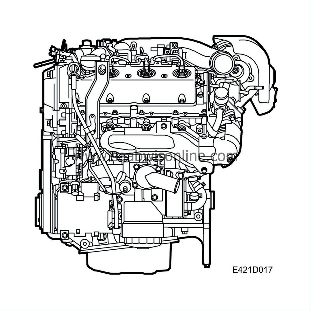
Engine block
| Engine block |
| Cylinder block |
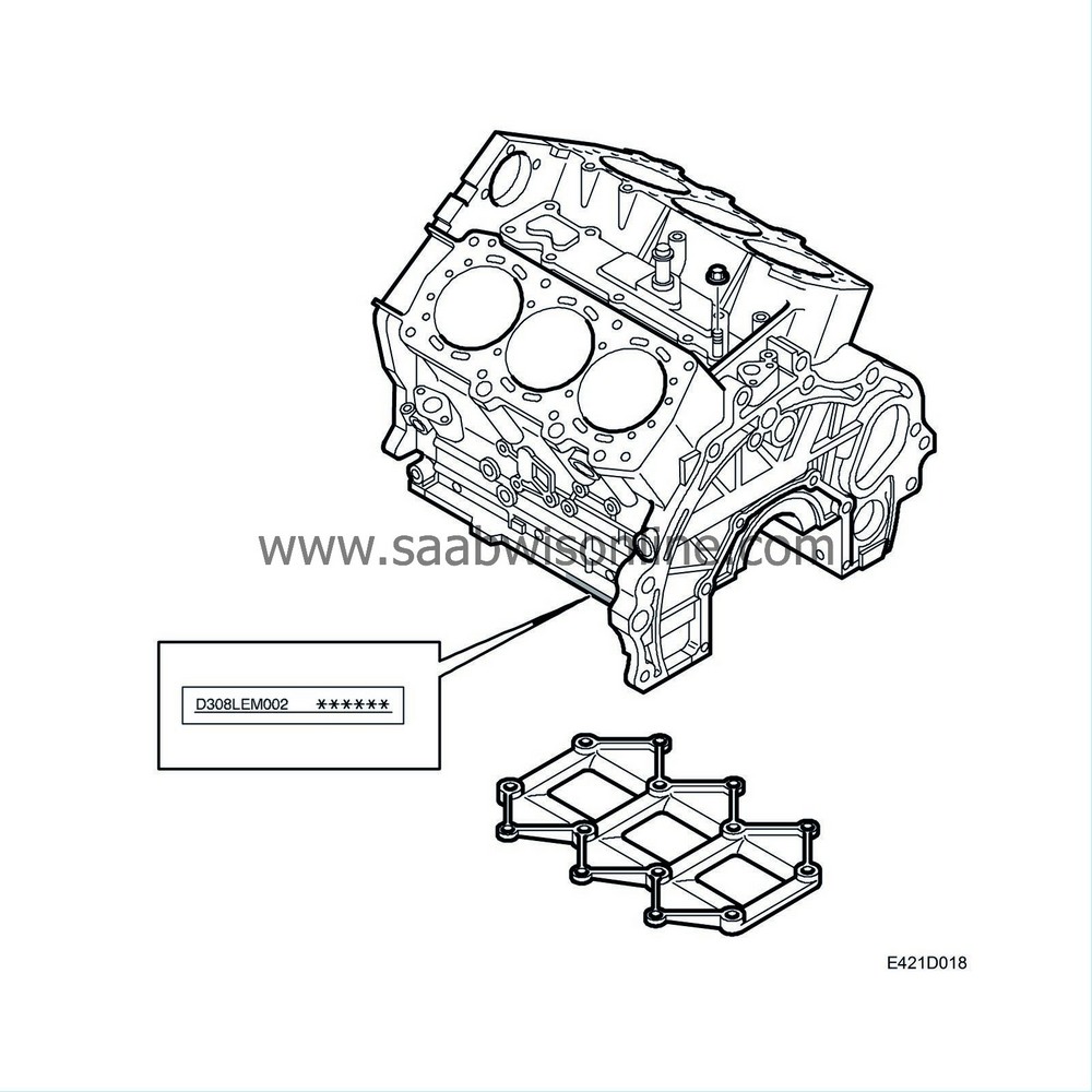
The cylinder block is precision cast in aluminium and made in one piece. The front bank cylinders are numbered 2 - 4 - 6, counted from the belt circuit side. The rear bank cylinders are number 1 - 3 - 5. The ignition sequence is 1 - 2 - 3 - 4 - 5 - 6. The cylinder banks are at a 66° angle to each other. The distance between cylinder centres is 102 mm. The cylinder linings are made of steel and are cast into the block, which means they cannot be changed. The cylinders are surrounded by coolant passages and there are oil passages for lubricant in the cylinder block.
| Main bearing member |
The crankshaft is located relatively high in the cylinder block, which gives more room for a main bearing member with high big-end bearing caps with extra bolted unions at the sides. The side bolts and main bearing member are used to stiffen the cylinder block and counteract the twisting effect caused by the high combustion pressure of the diesel engine. Vibration and noise are thereby suppressed.
| Cylinder head |
The cylinder head is precision cast in light alloy and bolted to the cylinder block. There are 2 intake valves and 2 exhaust valves per cylinder. The valve pairs are mounted in the cylinder head at an angle of 8° relative to each other. This angle allows a more compact combustion chamber in the pistons and consequently a more efficient combustion. The valve guides and valve seats are cylinder head mounted and are exchangeable. The tappets are mechanical and the valve clearance is adjusted with shims.
The electrically controlled injectors are located in the centre of each cylinder. Between the two injectors in each cylinder is a glow plug.
The seal between the cylinder head and the cylinder block is in the form of a metal gasket available in three thicknesses. Gaskets are marked with 1, 2 or 3 cut-outs depending on the thickness and an R for the rear cylinder bank and L for the front. Each cylinder head is fitted with 8x M12 bolts, of which the 4 inner ones are longer than the outer ones. Tightening is achieved with torque wrench and angle tightening.
| Timing covers |
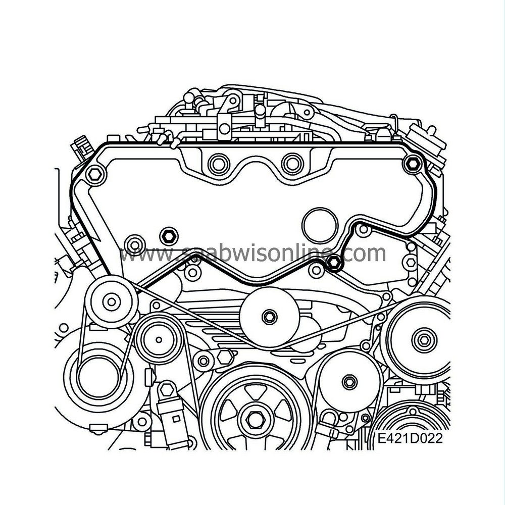
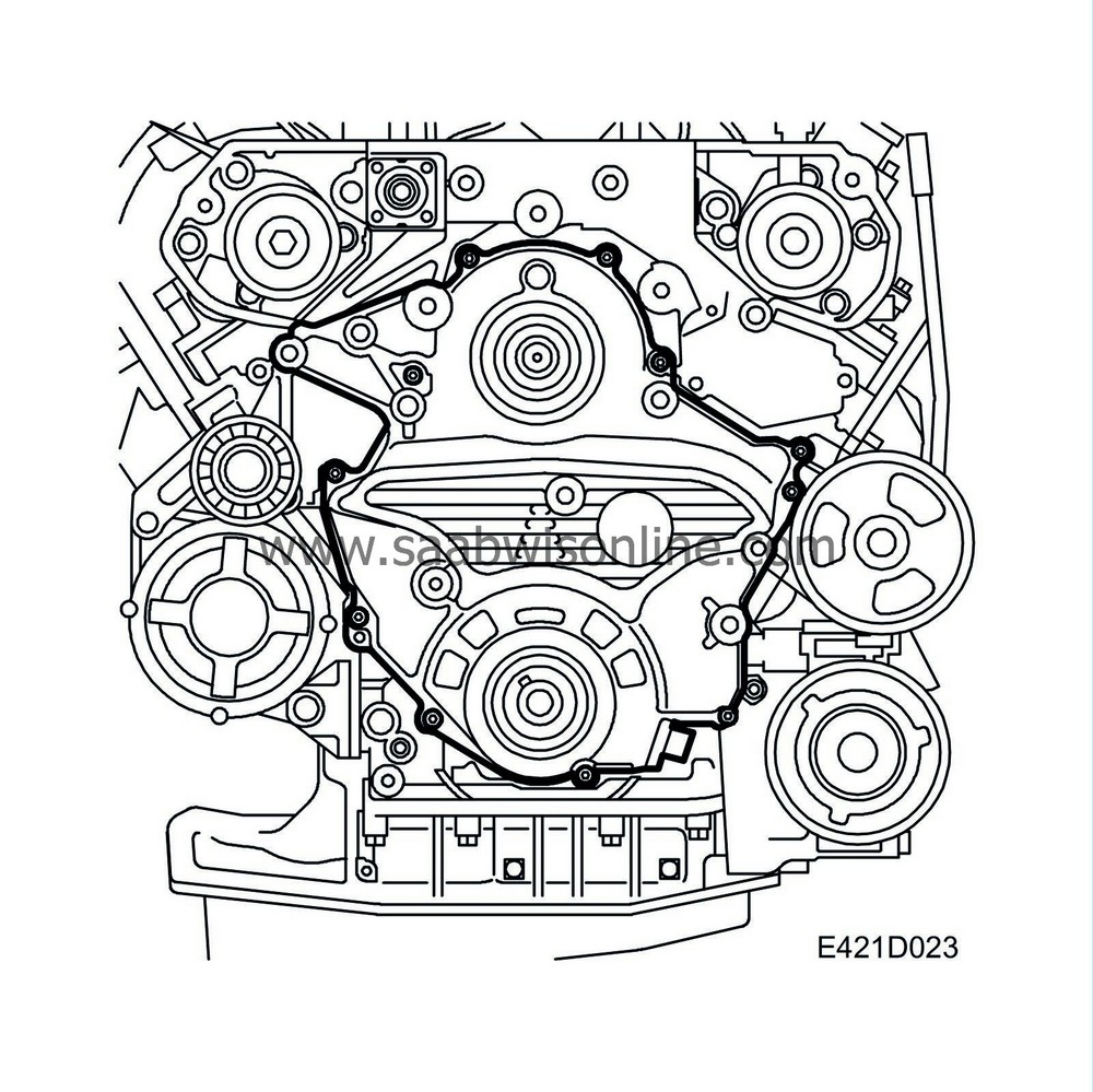
In the upper plastic timing cover is the timing belt, which drives the intake camshafts via the fuel pump. The exhaust camshafts are driven by gears from the intake camshafts. The lower timing cover is designed as a timing housing with separate aluminium cover. Behind this timing cover is an oil pump, which has a direct drive from the crankshaft, and a coolant pump that is driven by the crankshaft through a gear transmission. In addition, the fuel pump is driven by the crankshaft through a gear transmission. The cover is sealed using flange sealant.
| Crankshaft assembly |
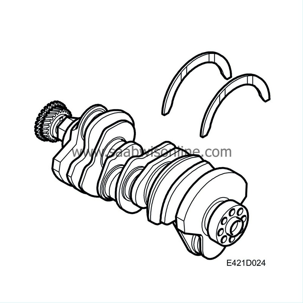
The crankshaft is forged and has ground, induction hardened, bearing journals. This provides a hard surface to protect against wear. The crankshaft is supported in 4 main bearings, where bearing 3 also acts as a thrust bearing. The crankshaft bearing carrier is machined together with the cylinder block in order to attain the best support and bearing clearance. Correct bearing clearance is essential to the running of the engine. Too little bearing clearance means insufficient lubrication and too great a clearance will increase engine wear.
The shaft has passages drilled in it for the lubricant. The sprocket for the crankshaft position sensor is a steel plate mounted on the crankshaft. It has 23 teeth that are read by the position sensor, which is mounted on the cylinder block.
| Pistons and connecting rods |
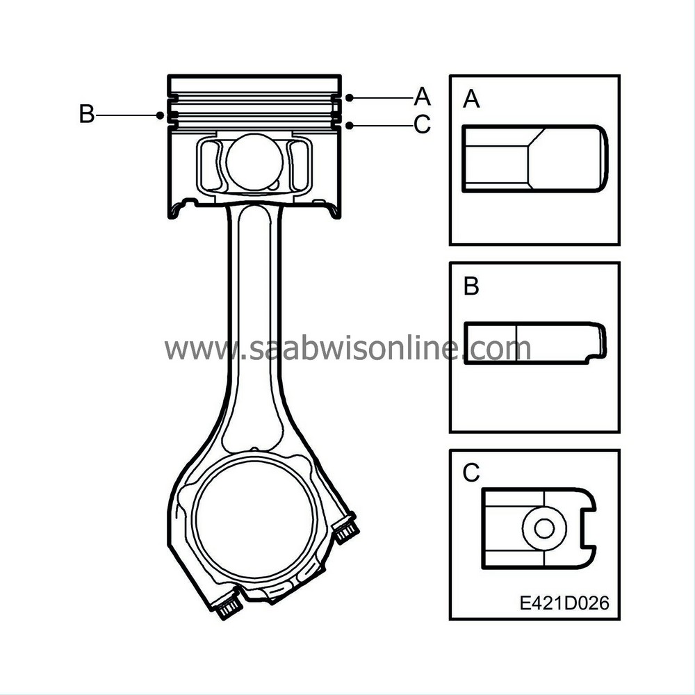
The pistons are made in light alloy and have grooves for two compression rings and one oil scraper ring. They are low friction pistons with integral combustion chambers. The floating gudgeon pins are fixed with circlips at the ends. The combustion chambers are situated on top of the pistons. The engine has nozzles that squirt oil onto the piston cooling passages for efficient cooling.
The connecting rods are manufactured of hardened steel with the big ends split in two. The little ends are trapezial, i.e. narrower at the top. The gudgeon pins are mounted 0.6mm from the centre of the piston. This is because such a position will counteract piston and cylinder bore wear and noise as the connecting rod moves from side to side when it is cranked and the downward piston force is directed downwards more effectively.
The design and appearance of the pistons rings also counteract oil consumption and noise. The lower compression ring is designed to add to the effect of the upper compression ring on its way up and add to the effect of the oil scraper ring on its way down.

