(260-2575) Replacing the O-ring in the coolant pump
Symptom: Coolant leakage at the coolant pump.
| MODIFICATION INSTRUCTION | |
| Bulletin Nbr: | 260-2575 |
| Date: ........... | Juli 2005 |
| Market: | enligt separat lista |
| Replacing the O-ring in the coolant pump |
| Service Campaign 157 22 |
Cars in stock must be rectified before delivery.
Cars already delivered must be rectified in connection with a scheduled visit to the garage for service or repairs.
| Cars affected |
Saab 9-5 M05 within VIN interval 53502502 - 53521624 with engine variant B235 and B205.
| Background |
There have been instances where the O-ring on the coolant pipe to the coolant pump does not fully fulfil the technical requirements. In some cases this can result in leakage of coolant from the O-ring. In some cases the coolant pump has been replaced unnecessarily to rectify the leakage. It is the defective O-ring which should be replaced.
Symptom description
Coolant leakage at the coolant pump.| Parts required |
30 551 913 O-ring (new material)
90 490 362 O-ring
79 87 415 O-ring
40-12 799 124 Coolant Saab longlife 4 l (approx. 3 litres are required when replacing the O-ring)
For fitting the modification identity plate:
12 785 148 Modification identity plate93 160 907 Cleaning agent Motip Dupli, aerosol 400 ml (sufficient for 50-100 cars)
| Procedure |
Checking the modification identity plate
Before proceeding, check box A3 of the modification identity plate. From and including M04 there is the table "Table of Modifications" in the car's Warranty and Service Book. A modification identity plate must be fitted in accordance with the section "Fitting the modification identity plate" where local directives require the marking of the car. If the box is not marked, continue as follows.To remove
| 1. |
Place protection over the front of the car.
|
|
| 2. |
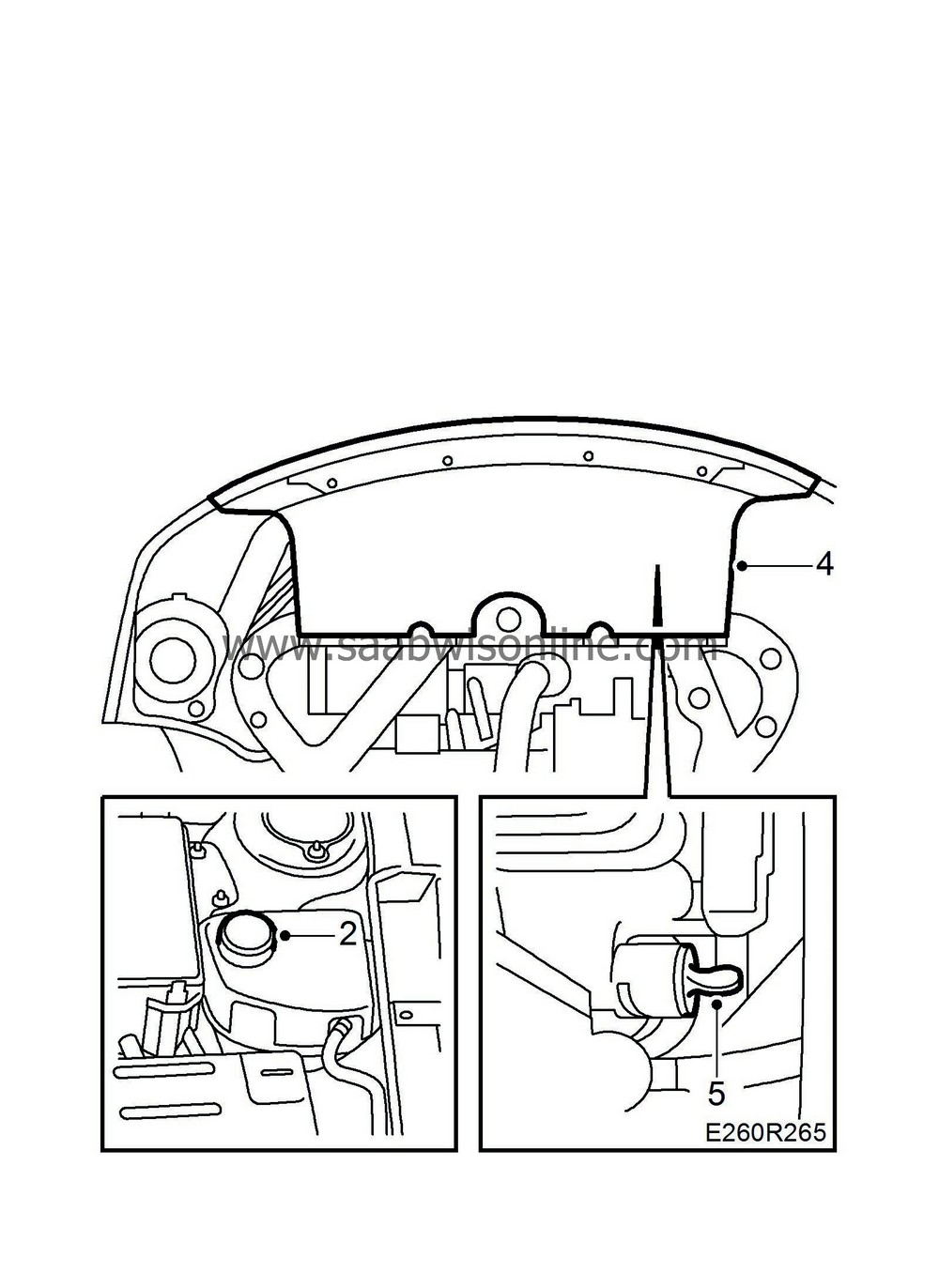
Open the expansion tank cap and release the overpressure.
|
|
| 3. |
Raise the car.
|
|
| 4. |
Remove the lower front cover.
|
|
| 5. |
Drain the coolant.
|
|
| 6. |
Lower the car.
|
|
| 7. |
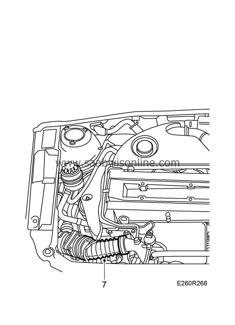
Remove the air hose from the turbocharger intake manifold.
|
|
| 8. |
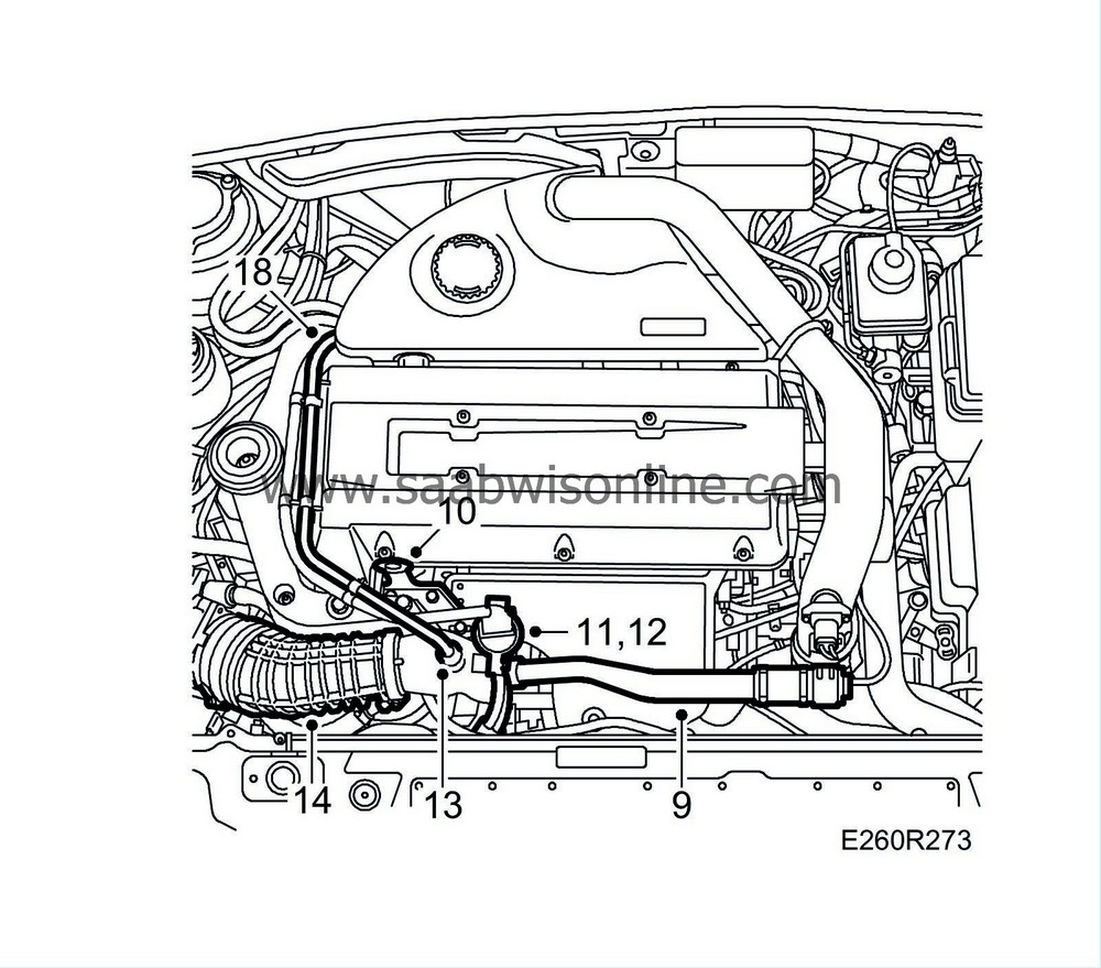
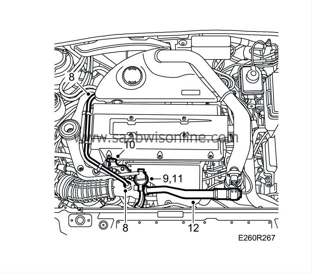
Detach the crankcase ventilation pipe from the turbocharger intake manifold and the camshaft cover.
|
|
| 9. |
Remove the connector from the solenoid valve.
|
|
| 10. |
Remove the engine's lifting eye.
|
|
| 11. |
Detach the turbocharger solenoid valve and move it aside.
|
|
| 12. |
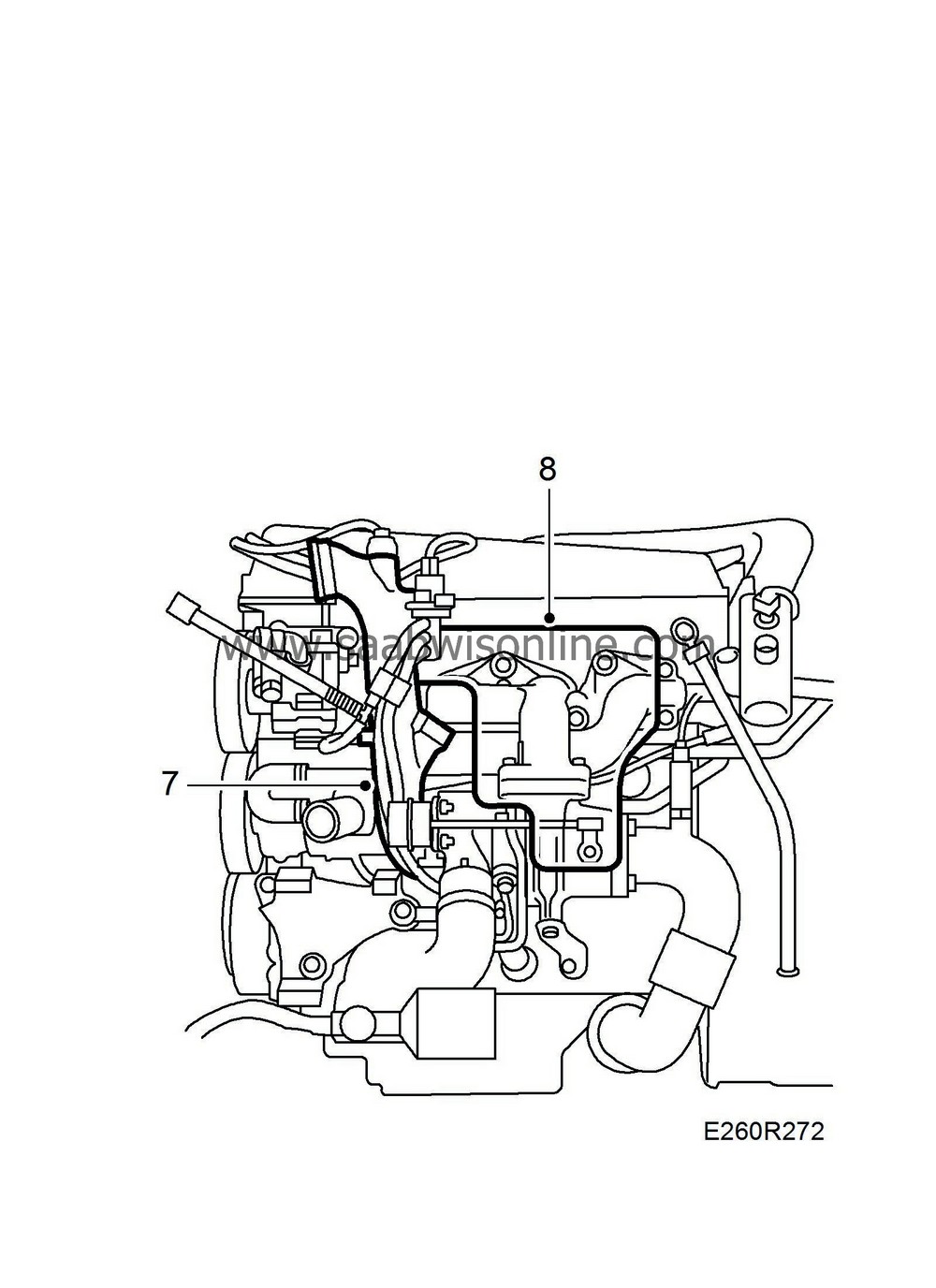
Remove the bypass pipe with the valve.
|
|||||||
| 13. |
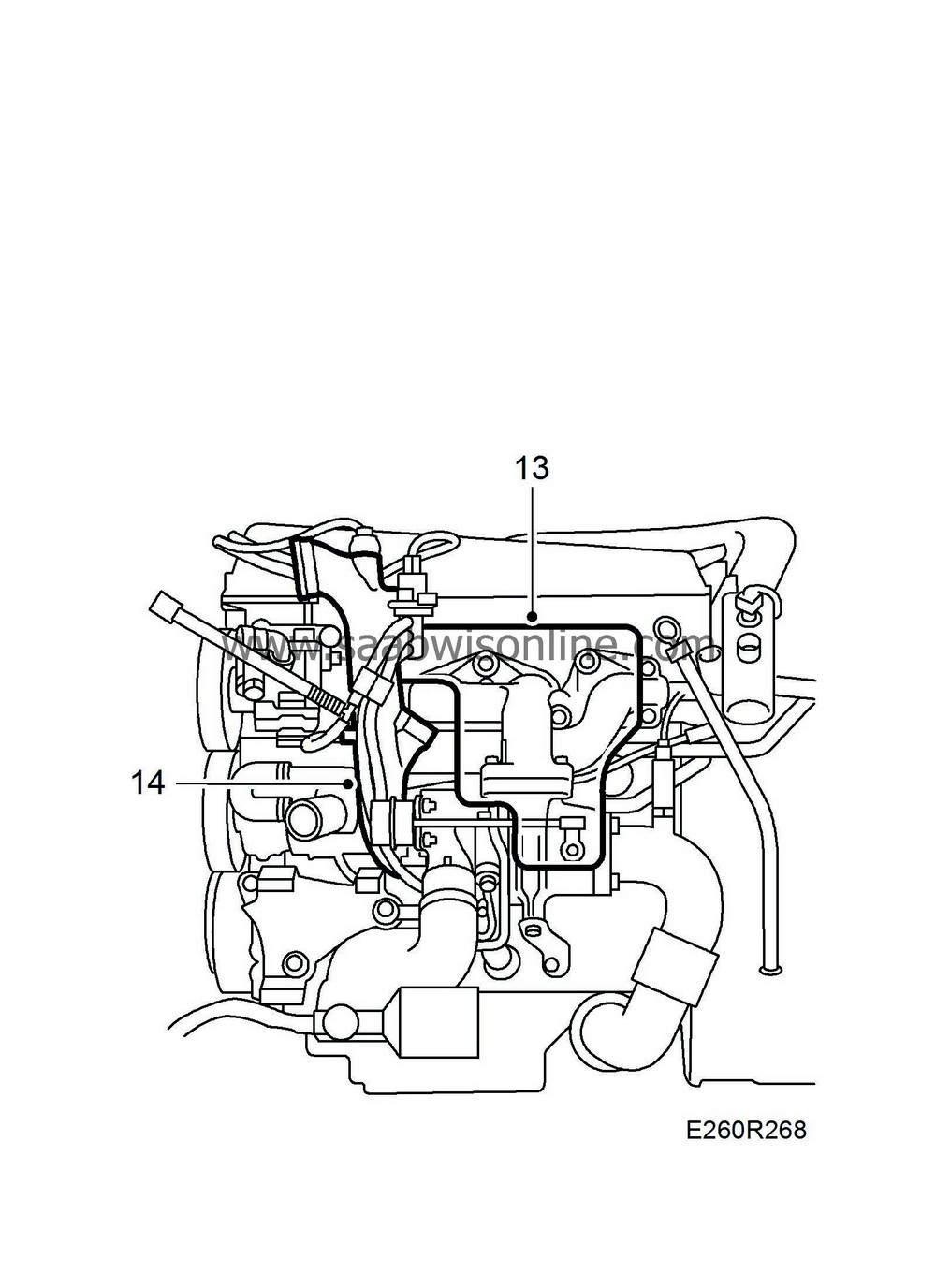
Remove the exhaust manifold heat shield. The heat shield is secured with a nut and two clips on the underside.
|
|
| 14. |
Remove the turbocharger intake manifold and detach the hose from the turbocharger solenoid valve.
|
|
| 15. |
Plug the turbocharger intake with a plastic plug or the like to prevent contaminants from being dropped into the turbocharger during this operation.
|
|
| 16. |
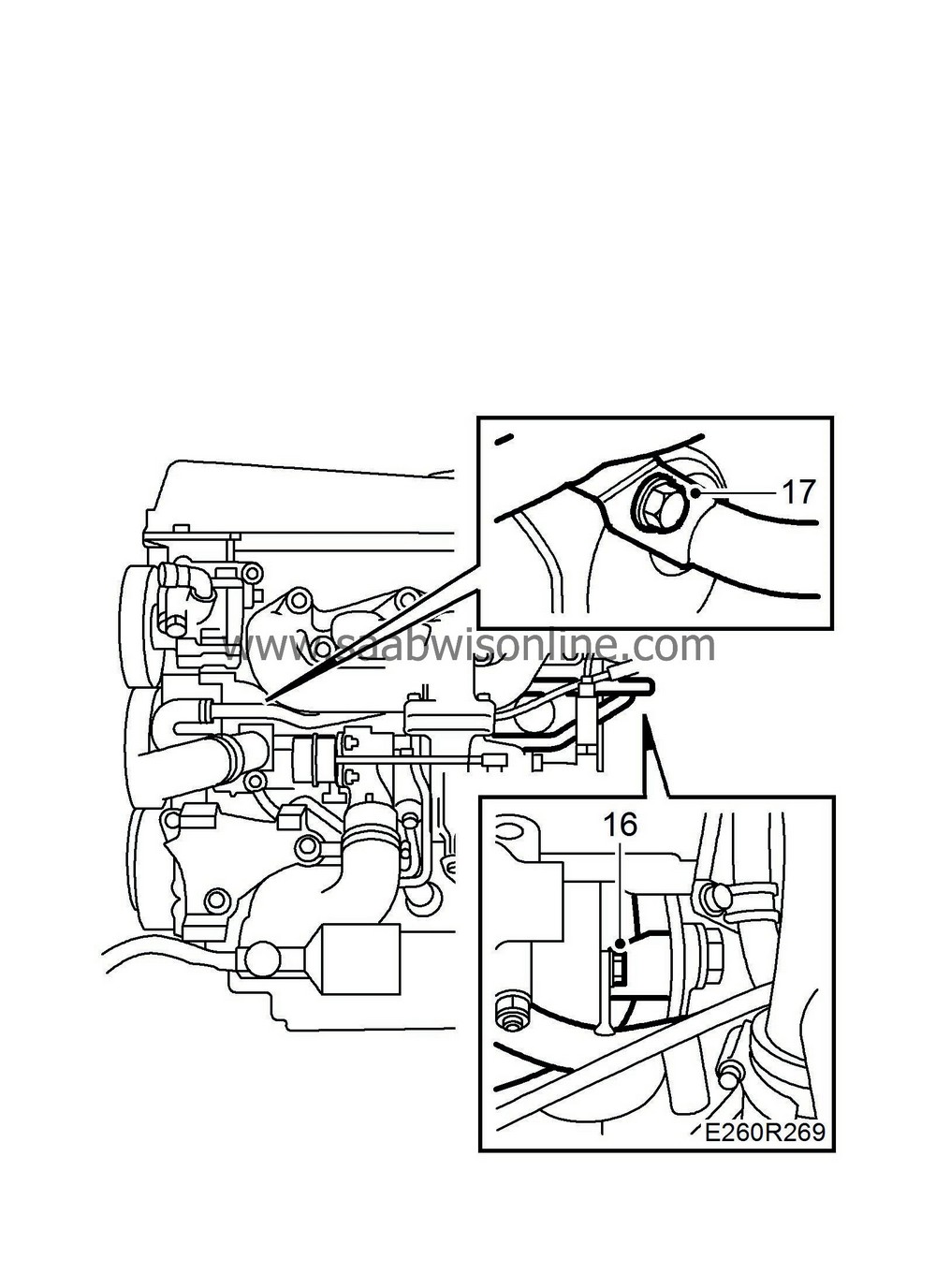
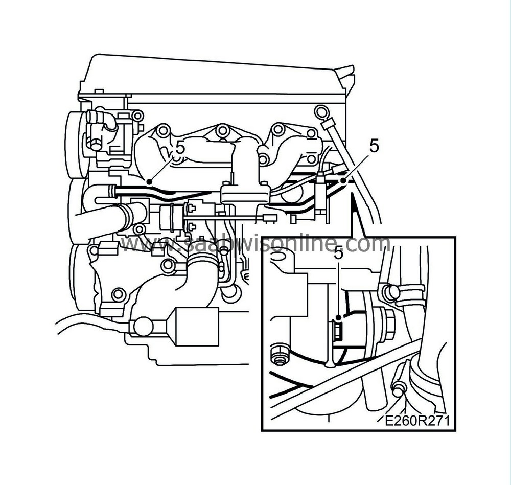
Detach both longitudinal coolant pipes from the cylinder block and the thermostat housing.
|
|
| 17. |
Detach both coolant pipes from the coolant pump.
|
|
To fit
| 1. |
Raise the car and close the drain cock.
|
|
| 2. |
Fit the lower front cover.
|
|
| 3. |
Lower the car.
|
|
| 4. |
Fit both longitudinal coolant pipes to the coolant pump. Use the new O-ring, greased with Vaseline.
Tightening torque 10 Nm (7 lbf ft) 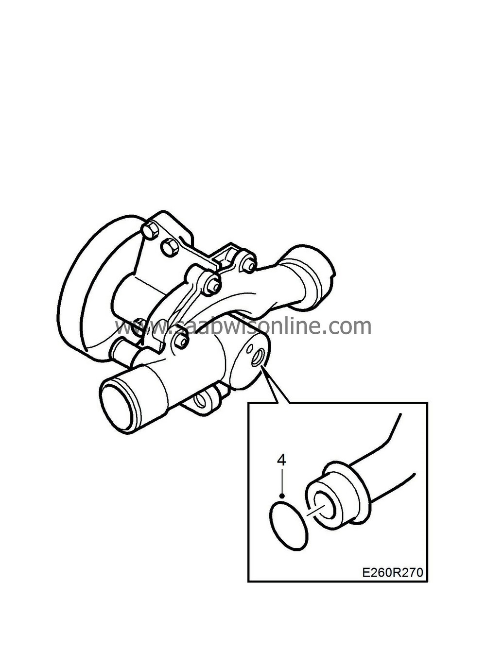
|
|
| 5. |
Fit both longitudinal coolant pipes to the cylinder block and the thermostat housing.
|
|
| 6. |
Pressure test the cooling system.
|
|
| 8. |
Fit the exhaust manifold heat shield.
Tightening torque 20 Nm (15 lbf ft) |
|
| 10. |
Fit the engine's lifting eye.
|
|
| 11. |
Fit the turbocharger solenoid valve.
|
|
| 12. |
Attach the connector to the solenoid valve.
|
|
| 13. |
Fit the crankcase ventilation pipe to the turbocharger intake manifold and the camshaft cover.
|
|
| 14. |
Fit the air hose to the turbocharger intake manifold.
|
|
| 15. |
Fill with coolant to the MAX level. For the correct mixture ratio see, WIS - Engine - Cooling system - Technical data - Coolant. Close the expansion tank cap.
|
|
| 16. |
Set the A/C and ACC to OFF position. Start and run the engine to operating temperature without any load, preferably with varied engine speed until the radiator fan starts.
|
|
| 17. |
Switch off the engine and top up to the MAX level.
|
|
| 18. |
Check for any leakage.
|
|
| 19. |
Remove the protection from the front of the car.
|
|
| Marking the modification identity plate |
After carrying out the procedure, box A3 on the modification identity plate must be marked. From and including M04 the table "Table of Modifications" can be found in the car's Warranty and Service Book. Mark the box with the number "7" if the procedure was carried out by the importer or with the number "8" if carried out by the dealer.
| Fitting the modification identity plate |
| Note | ||
|
A modification identity plate must only be fitted where local directives require the marking of the car. |
Fit the modification identity plate according to WIS
9-5 M04 - General - General - Technical data - Plates and labels
| Warranty/Time Information |
See separate information.

