Mass air flow sensor
| Mass air flow sensor |

The mass air flow sensor is used continuously during operation to measure the air mass available for combustion. The sensor comprises two main parts, a connection pipe and the actual sensor.
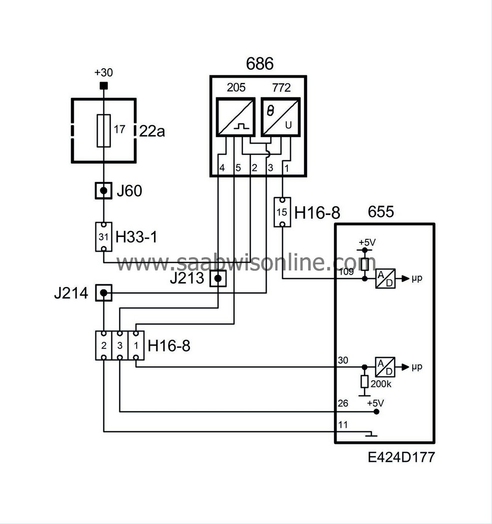
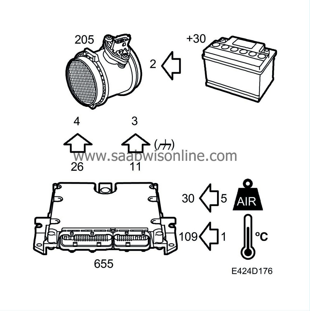
The mass air flow sensor is supplied with 5V from pin 26 on the control module to pin 4 on the sensor and with 12V from fuse 17 to pin 2 on the sensor. The sensor is grounded through pin 3 to control module pin 11. The control module's sensor inputs, pin 30, are connected to pin 5 on the mass air flow sensor, with the voltage varying in relation to air mass.
Measurement is conducted in the following way. Some of the air flow through the mass air flow sensor passes a measuring plate. The surface of this plate is a thin diaphragm of semi-conductor type on which a heating element and a number of temperature sensors are fitted. The heating element is a resistor, which radiates heat when current passes through it. Together with the resistor, there is a temperature sensor that enables the heat in the heating element to be regulated exactly. The temperature of the heating element is dependent on the temperature of the incoming air.
There are two more temperature sensors on the diaphragm, one upstream and one downstream from the heating element seen from the direction of the airflow. If there is no air flowing past the diaphragm, the temperature will be the same across its entire surface. The two temperature sensors upstream and downstream from the heating element will then detect the same temperature.
When air starts to flow through the mass air flow sensor, the diaphragm upstream from the heating element will cool down, which the temperature sensor on the diaphragm will detect. The temperature of the diaphragm and the temperature sensor downstream from the heating element will be the same as before the airflow started.
By measuring the difference in temperature of the airflow between the two temperature sensors (upstream and downstream), the air mass can be calculated.
The direction of flow can also be determined by taking into account which of the temperature sensors is the warmest and the coldest respectively. All the necessary calculations are carried out in the mass air flow sensor.
The signal, which is available to the engine management control module, consists of the calculated air mass and the temperature of the incoming air.
The inner air duct has a protective mesh that separates any water that may enter and prevents function disruption by dust particles or oil mist from the crankcase ventilation.
| Diagnostics |
If the control module registers a malfunction in the mass air flow sensor, DTC P0101 will be generated.
If the control module output is short-circuited to ground/break, DTC P0102 will be generated.
If the control module output is short-circuited to B+, DTC P0103 will be generated.
System reaction to a fault
| • |
The control module uses 1200 mg/cyl as a substitute value.
|
|
| • |
Exhaust recirculation and boost pressure control are disengaged.
|
|
| • |
The following limitations will apply: Pedal position sensor adjustable to max 40%, fuel quantity max 30 mm
3
/combustion.
|
|


