Injectors, V6
| Injectors, V6 |
| To remove |
|
||||||||||||||||||||||
| Important | ||
|
Be particulary observant regardning cleanliness when working on the fuel system. Loss of function may occur due to very small particles. Prevent dirt and grime from entering the fuel system by cleaning the connections and plugging pipes and lines during disassembly. Use 82 92 948 Plugs, A/C system assembly. Keep components free from contaminants during storage. |
||
| 1. |
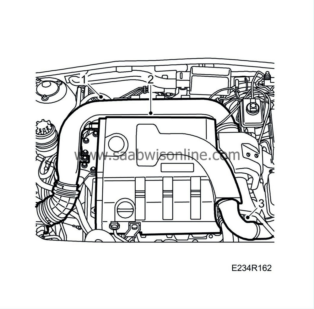
Remove the intake manifold from the mass air flow sensor and turbo.
|
|
| 2. |
Remove the upper engine cover.
|
|
| 3. |
Detach the turbo pressure hose from the intake manifold.
|
|
| 4. |
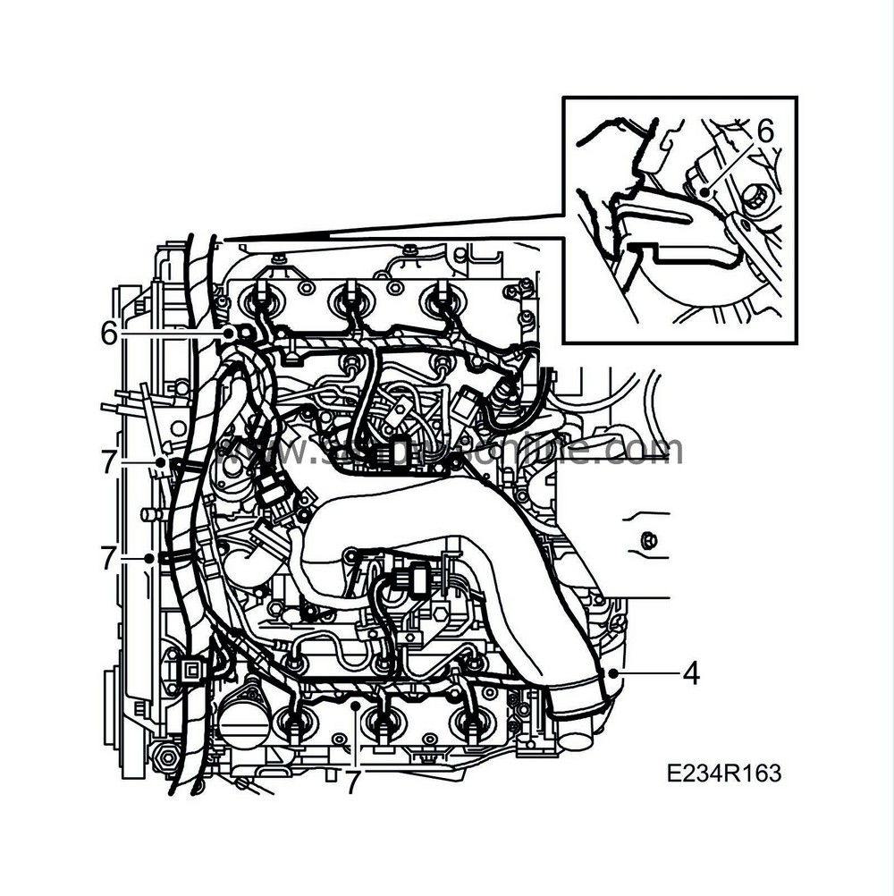
Remove the upper intake manifold.
|
|
| 5. |
Unplug the connectors for the injectors and the coolant temperature sensor; detach the charge air pressure sensor, the camshaft position sensor, the turbo vacuum clock and the EGR valve. Remove the cable ducts from the camshaft covers.
|
|
| 6. |
Remove the cable holder from the rear camshaft cover and the generator bracket.
|
|
| 7. |
Free the wiring secured to the fuel feed and fuel return pipes.
|
|
| 8. |
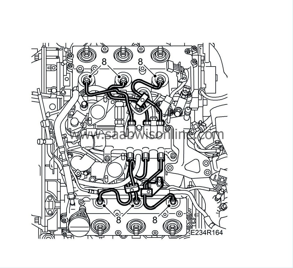
Remove the fuel injection pipes.
|
|||||||||
| 9. |
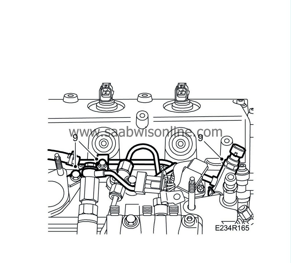
Detach the rear bank's fuel return pipe with mounting from the camshaft frame and the fuel rail. Move the pipes aside.
|
|
| 10. |
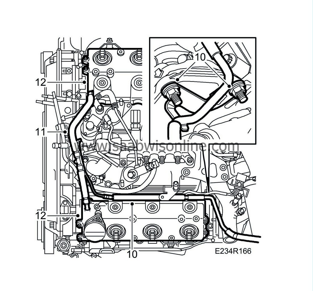
Detach the front coolant pipe from the intake manifold and the cylinder head.
|
|
| 11. |
Detach the crankcase ventilation hoses from the camshaft covers.
|
|
| 12. |
Remove the camshaft covers from the cylinder banks.
|
|
| 13. |
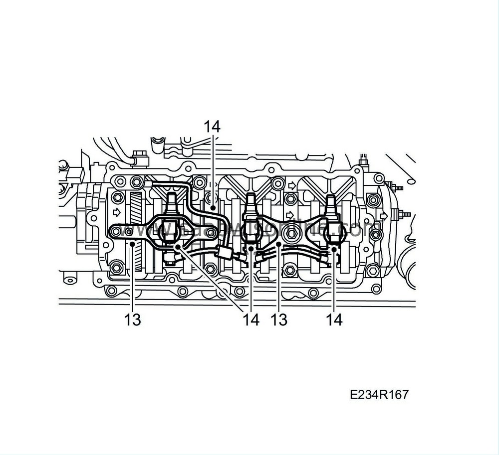
Remove the injector holders.
|
|
| 14. |
Remove the injectors and the fuel return pipes.
|
|
| To fit |
| 1. |
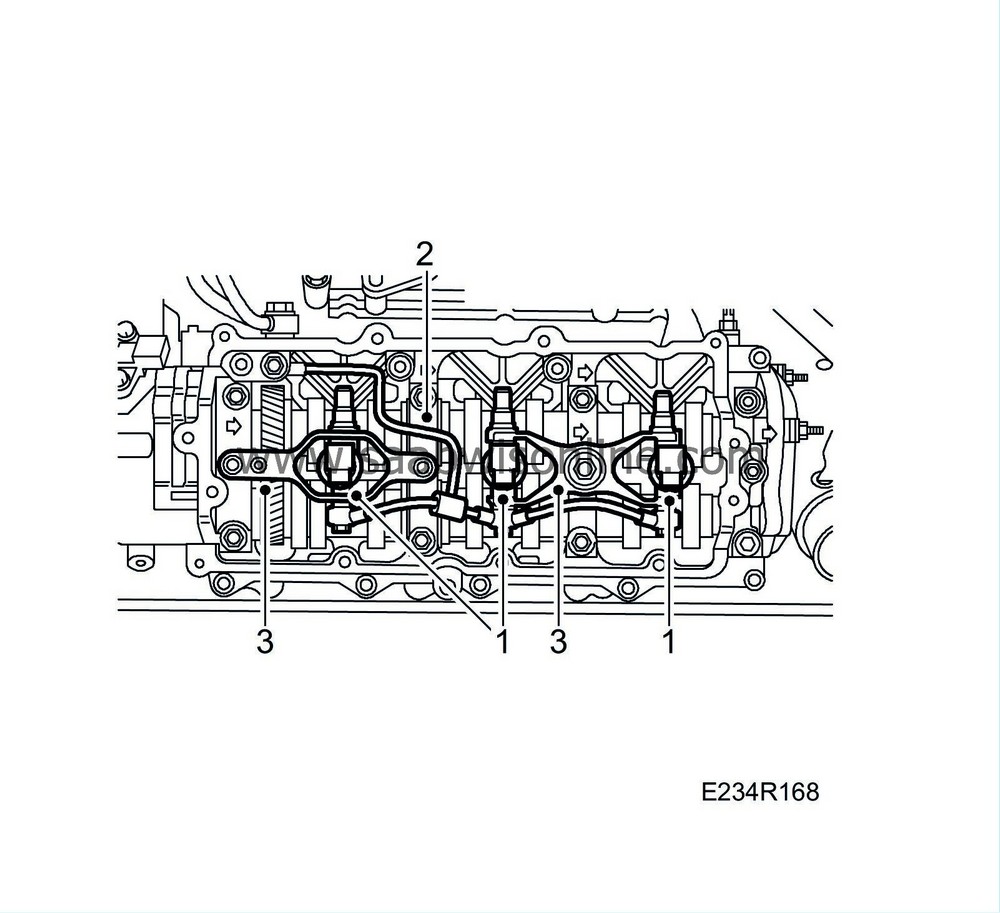
Fit the injectors using new seals.
|
||||||||||
| 2. |
Fit the fuel return pipes on the injectors. Make sure that the double sealing washer does not stick out and get caught against the camshaft cover sealing surface.
Tightening torque: 20 Nm (15 lbf ft) |
|
| 3. |
Fit the injector holders. make sure the holder goes down in the injector slot. Tighten the nuts evenly.
Tightening torque, small nuts 5 Nm (4 lbf ft) Tightening torque, large nuts 29 Nm (21 lbf ft) |
|
| 4. |
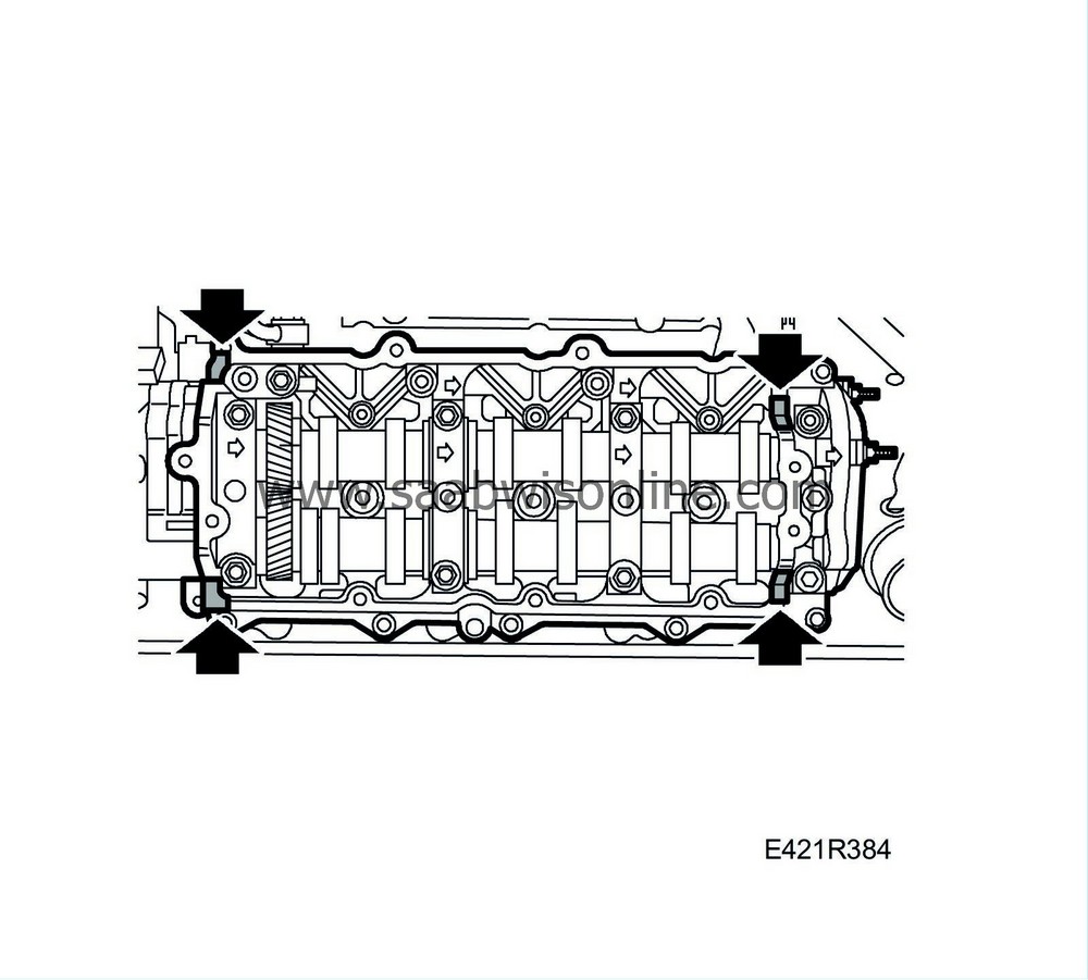
Fit the camshaft covers using new seals; see
Replacing camshaft cover seals
. Apply flange sealant, part no. 87 81 841, to the corners of each cover as illustrated.

|
|
| 5. |
Fit the crankcase ventilation hoses to the camshaft covers.
|
|
| 6. |
Fit the front coolant pipe to the intake manifold and cylinder head.
|
|
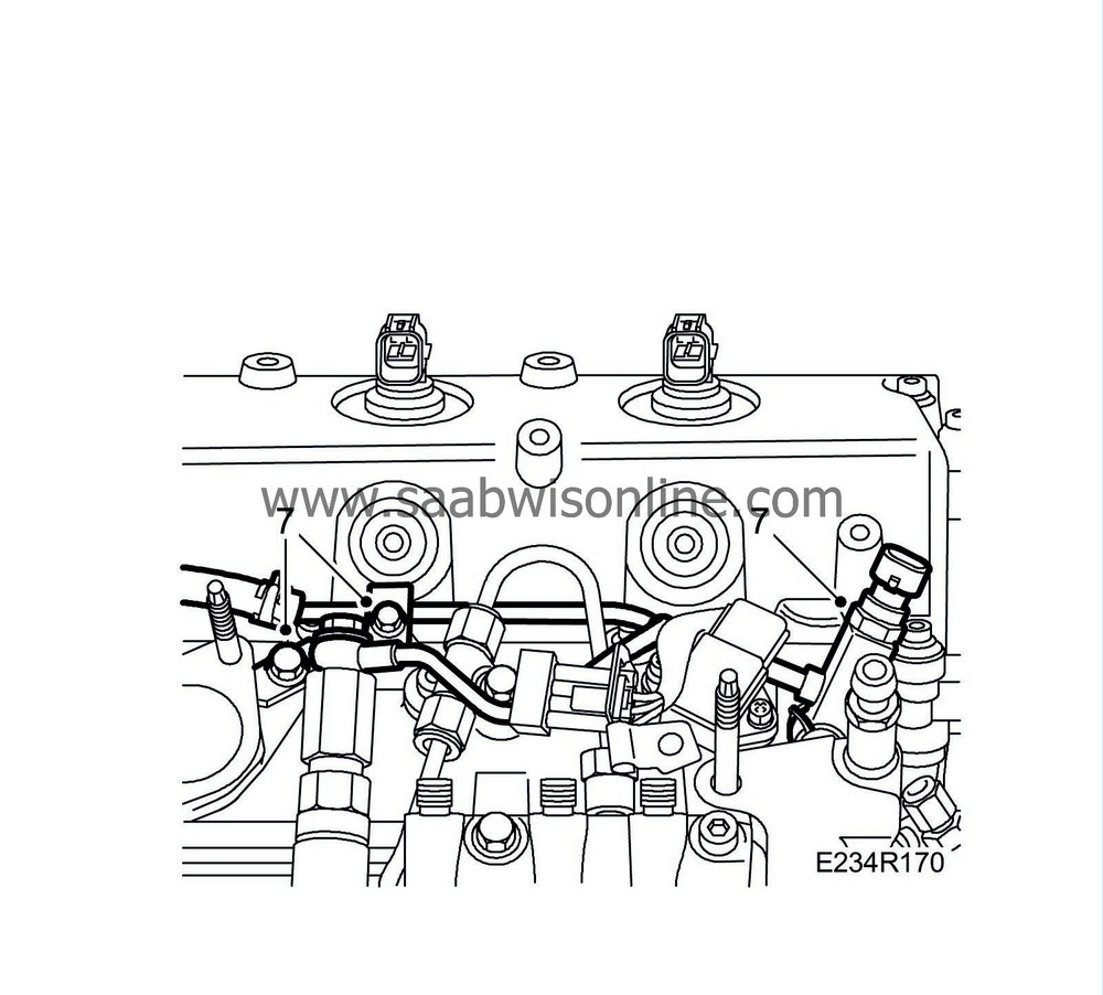
| 7. |
Fit the fuel return pipe and its mounting to the rear cylinder bank using new seals.
|
|
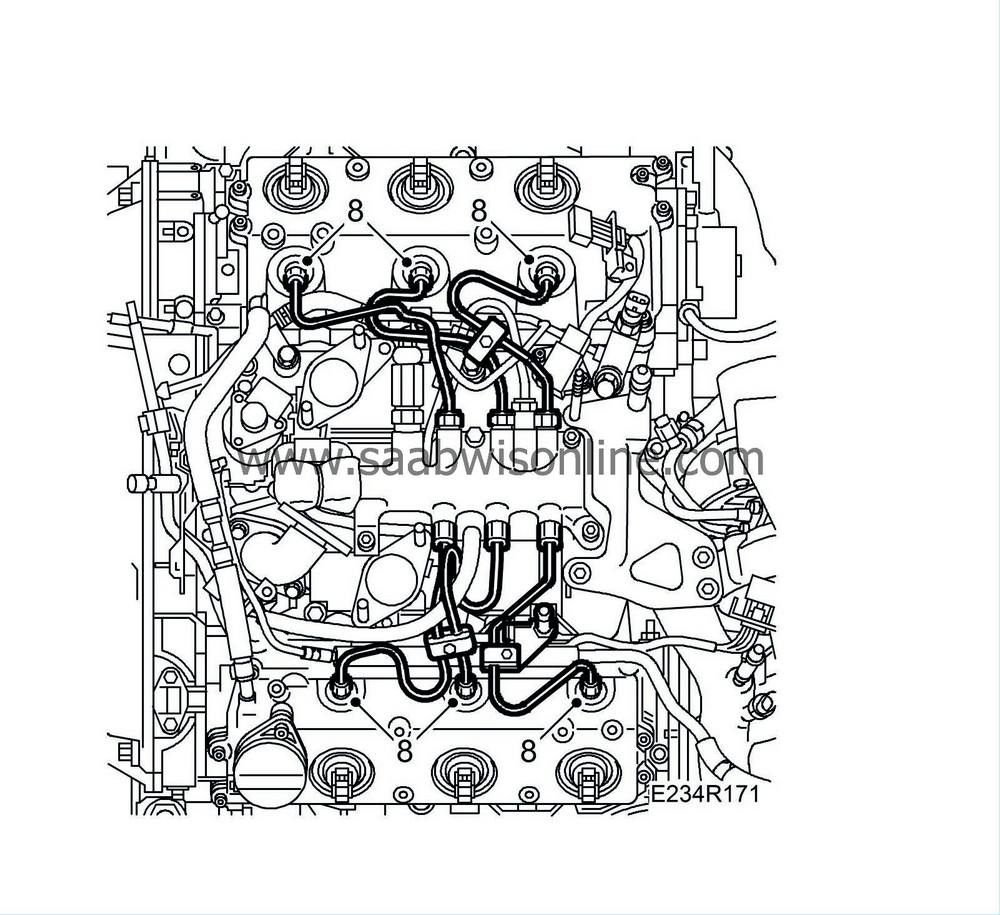
| 8. |
fit the injection pipes. Make sure that the wiring between the injection pipes to cylinders 2 and 4 is correctly situated.
|
|
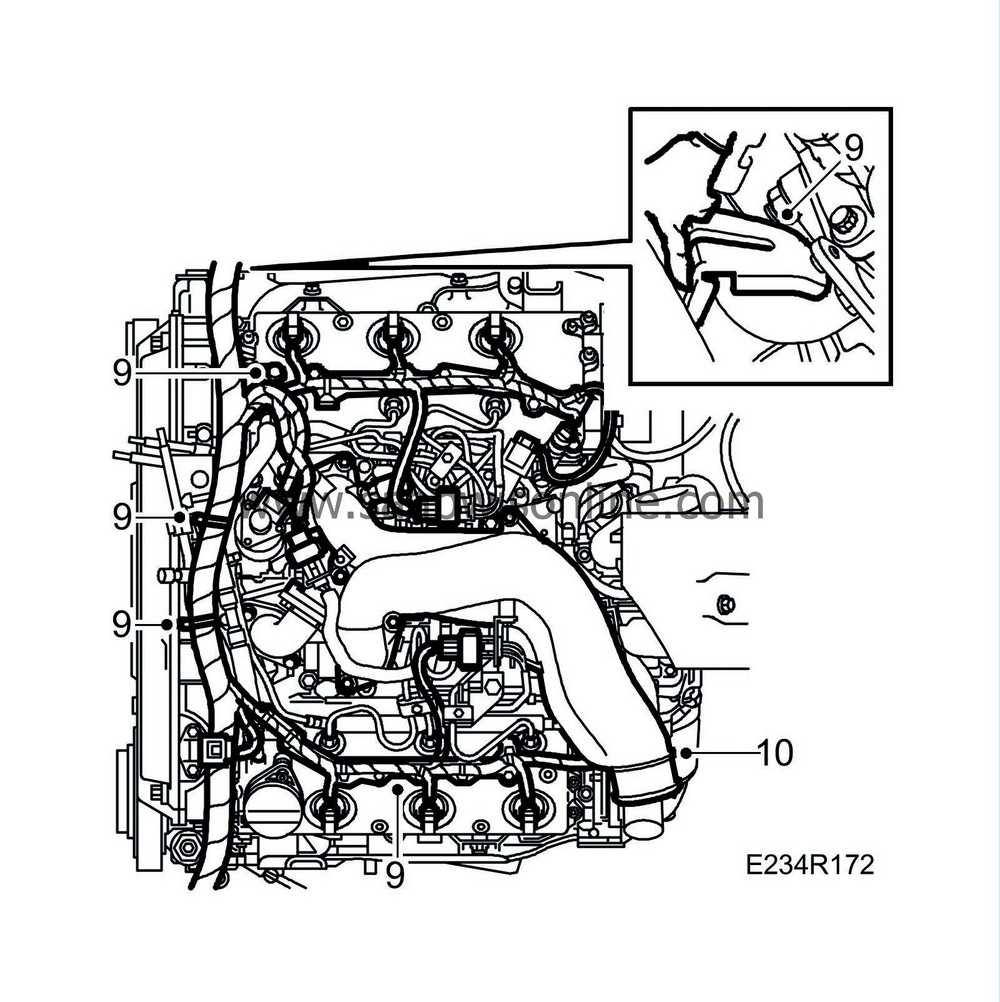
| 9. |
Fit the cable ducts and plug in its connectors.
|
|
| 10. |
Fit the upper intake manifold using new seals.
|
|
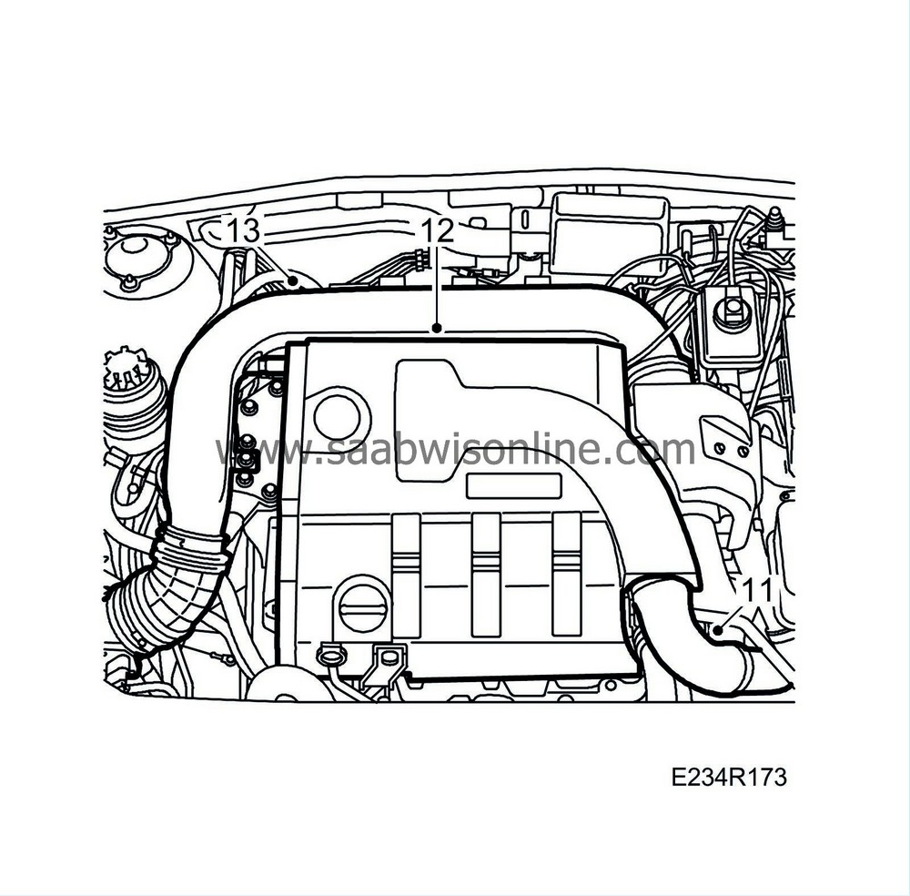
| 11. |
Fit the turbo pressure hose to the upper intake manifold.
|
|
| 12. |
Refit the upper engine cover.
|
|
| 13. |
Fit the intake manifold to the mass air flow sensor and the turbo.
Tightening torque, mass air flow sensor: 3.5 Nm (2.5 lbf ft) |
|

 Warning

