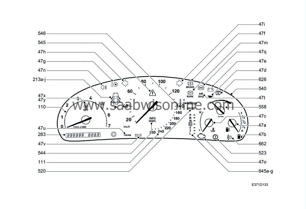
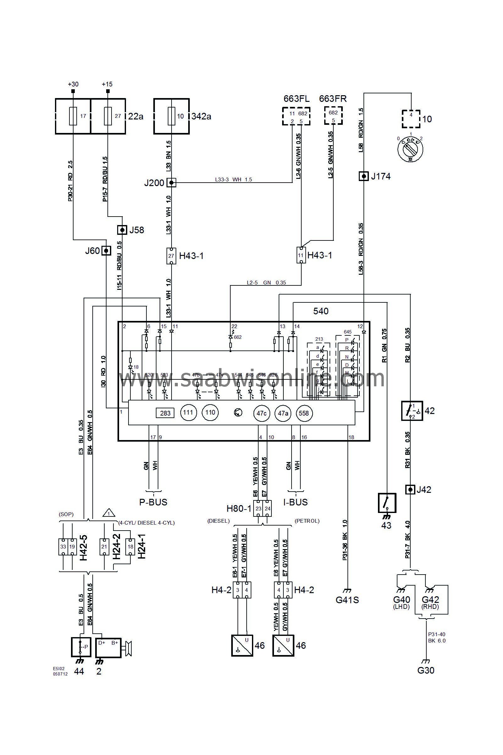
Main Instrument Unit (MIU)
| Main Instrument Unit (MIU) |
| List of components |
| No. | Name location | Illustration |
|
|
Components |
|
|
2
|
Alternator,
on the rear of the engine (RH) |

|
|
10
|
Light switch,
on the instrument panel between the steering wheel and the driver's door |

|
|
11FL
|
Bulb, LH main beam,
in the LH headlamp |

|
|
22a
|
Fuse box, instrument panel,
on the short edge of the instrument panel by the driver's door |

|
|
42
|
Level switch, brake fluid,
on the brake fluid reservoir |

|
|
43
|
Contact, handbrake,
under the floor console by the handbrake |

|
|
44
|
Pressure switch, engine oil
4-cyl: under the intake manifold V6: on the RH end of the engine under the alternator |

|
|
46
|
Fuel level sensor,
in the fuel tank |

|
|
342a
|
Fuse box, engine compartment,
behind the battery |

|
|
540
|
Main instrument unit,
in front of the driver in the instrument panel |

|
|
663FL
|
LH headlamp
to the left of the radiator |

|
|
663FR
|
RH headlamp
to the right of the radiator |

|
|
682
|
Control module, headlamp,
in headlamp |
FL
FR |
|
4-pin connector |
||
|
H4-2
|
Under the rear seat
|

|
|
24-pin connector |
|
|
|
H24-1
|
Grey connector located centrally on the bulkhead partition (engine compartment side)
|
|
|
H24-2
|
Black connector located centrally on the bulkhead partition (engine compartment side)
|
|
|
42-pin connector |
||
|
H42-5
|
In the middle of the bulkhead partition (engine compartment side)
|

|
|
43-pin connector |
||
|
H43-1
|
White connector in the connector console under the A-pillar
|

|
|
80-pin connector |
||
|
H80-1
|
In the connector console under the A-pillar
|

|
|
Crimp connectors |
||
|
J42
|
LHD:
Approx. 145 mm from grounding point G40 branching point towards main fuse box
RHD: Approx. 50 mm from the branching point to grounding point G42, towards the relay centre |

|
|
J58
|
LHD:
Approx. 50 mm from branching MIU towards DICE control module
RHD: Approx. 260 mm from rear of DICE control module connector towards the engine bay |

|
|
J60
|
LHD:
Approx. 40 mm from branching DICE control module towards the main fuse box
RHD: Approx. 240 mm from rear of DICE control module connector towards the engine bay |

|
|
J174
|
LHD:
Approx. 140 mm from branching of H33-1 connector towards main fuse box
RHD: -- |

|
|
J200
|
Approx. 380 mm from branching of brake unit towards engine bay main fuse box
|

|
|
Grounding points |
||
|
G30
|
In the engine compartment on the side plate in front of the LH wheel housing
|

|
|
G40
|
In the cabin on the LH side of the knee beam
|

|
|
G41S
|
LH ground screw in the middle of the knee beam (in the cabin)
|

|
|
G42
|
In the cabin on the RH side of the knee beam
|

|
| Warning and indicator lamps |


