Combustion air fan
| Combustion air fan |
| To remove |
| 1. |
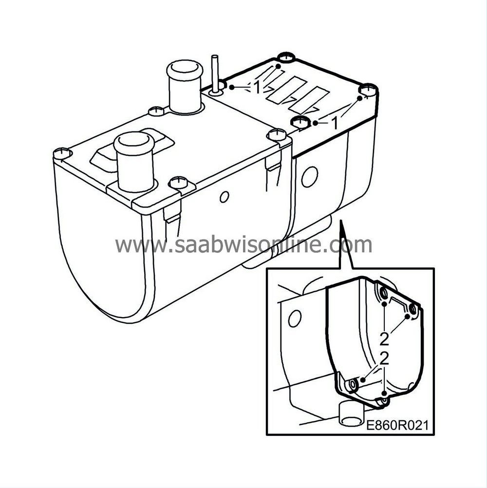
Remove the cover over the combustion air fan.
|
|||||||
| 2. |
Remove the four control module bolts.
|
|
| 3. |
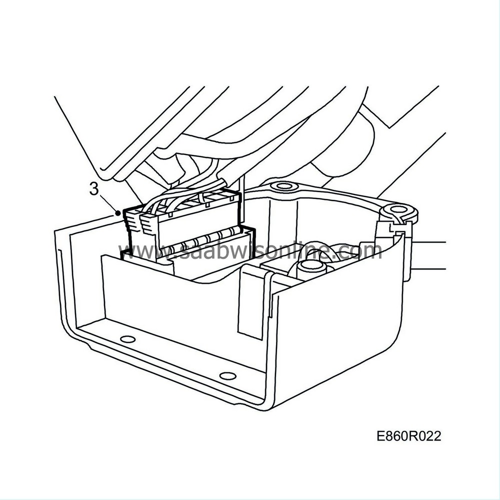
Carefully extract the control module, unplug the connector and remove the control module from the heater.
|
|
| 4. |
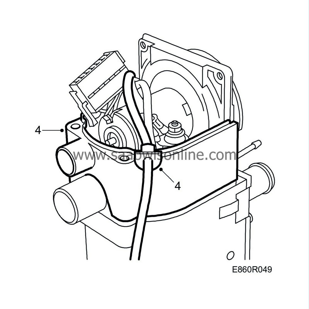
Remove the centre housing.
|
|
| 5. |
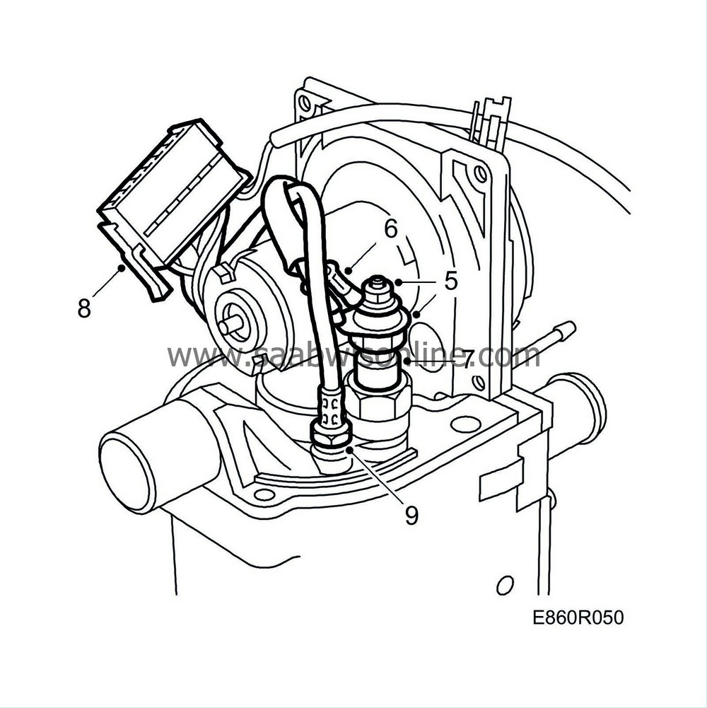
Undo the nut and remove the glow plug cables.
|
|
| 6. |
Bend the cables aside.
|
|
| 7. |
Remove the glow plug.
|
|
| 8. |
Open connector B2 and extract the leads for the flame temperature sensor. Use tool 85 80 110.
|
|
| 9. |
Remove the flame temperature sensor.
|
|
| 10. |
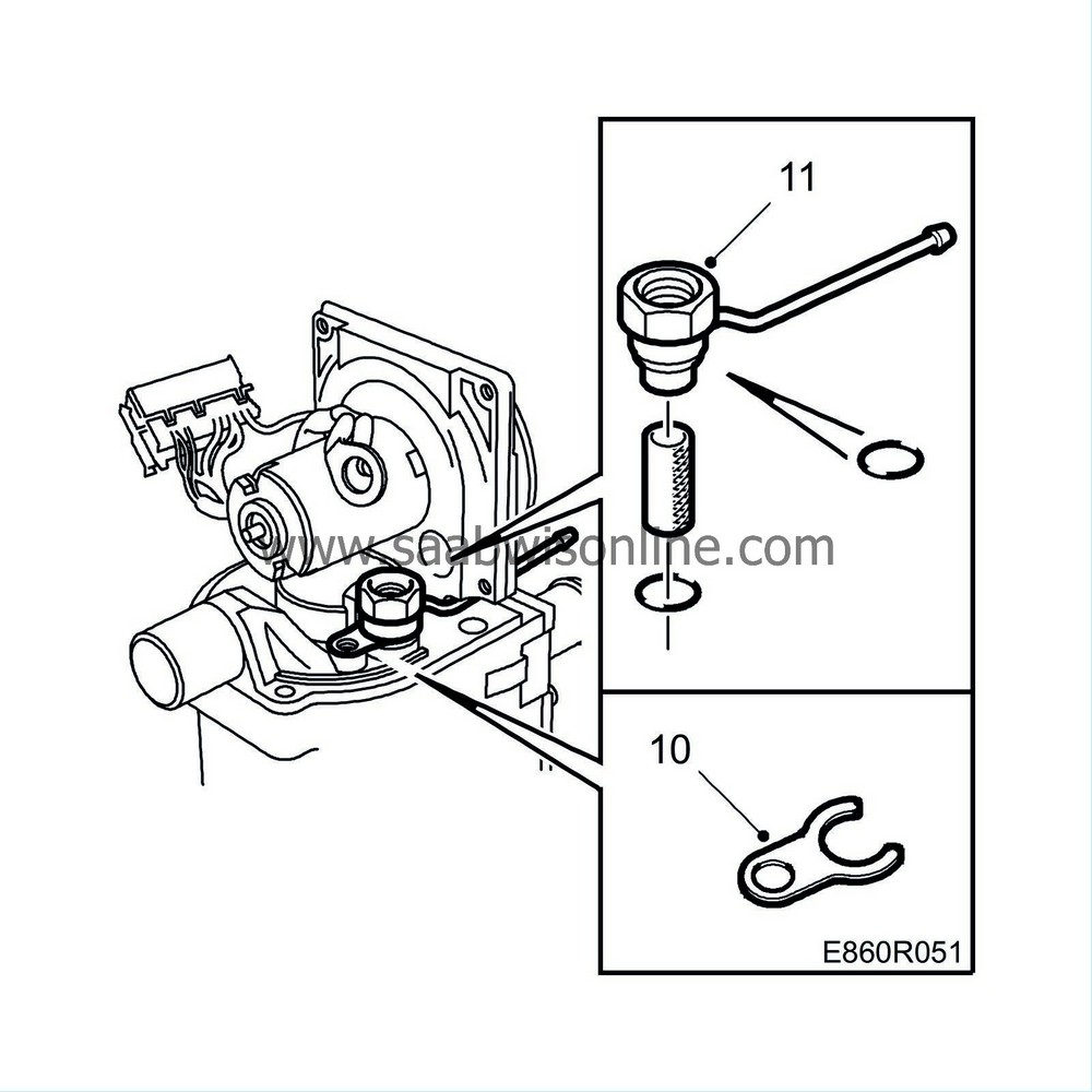
Remove the holder (fork) which secures the glow plug holder in position.
|
|
| 11. |
Extract the glow plug holder with filter.
|
|
| 12. |
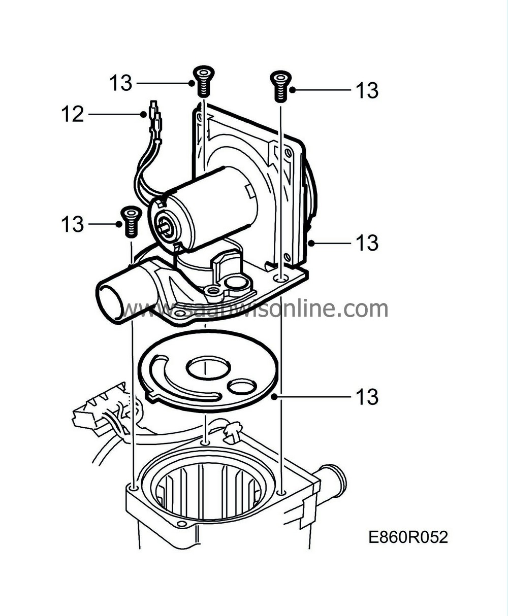
Extract the leads for the combustion air fan from connector B2. Use tool 85 80 110.
|
|
| 13. |
Remove the combustion air fan. Remove the gasket.
|
|
| To fit |
| 1. |
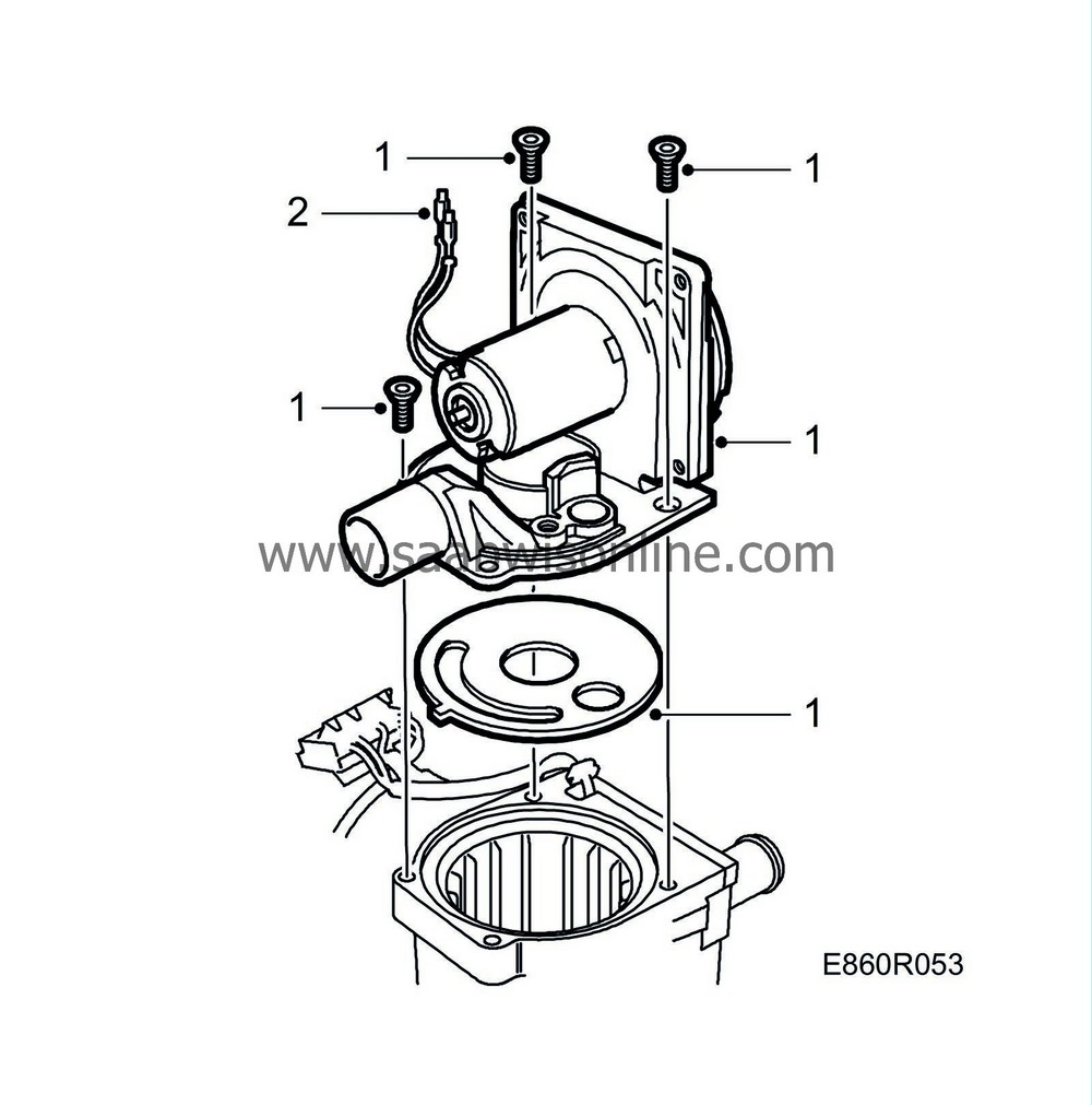
Change the gasket and fit the combustion air fan. Align the gasket with the three holes.
|
|
| 2. |
Fit the combustion air fan leads in connector B2.
|
|||||||
| 3. |
Change O-rings and fit the glow plug holder with filter.

|
|
| 4. |
Refit the fork.
|
|
| 5. |
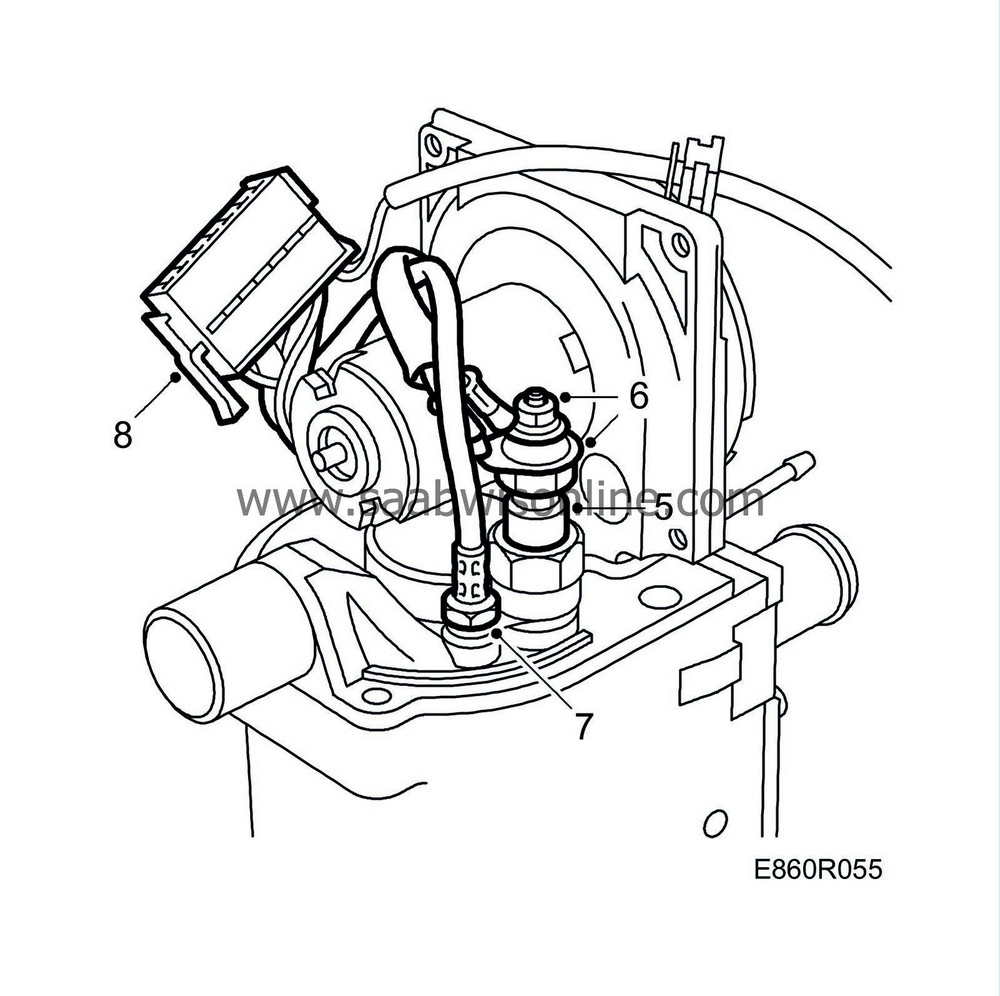
Change the O-ring and fit the glow plug.
|
|
| 6. |
Connect the cables to the glow plug and tighten the nut.
|
|||||||
| 7. |
Fit the flame temperature sensor.
|
|
| 8. |
Fit the flame temperature sensor's leads in connector B2.
|
|||||||
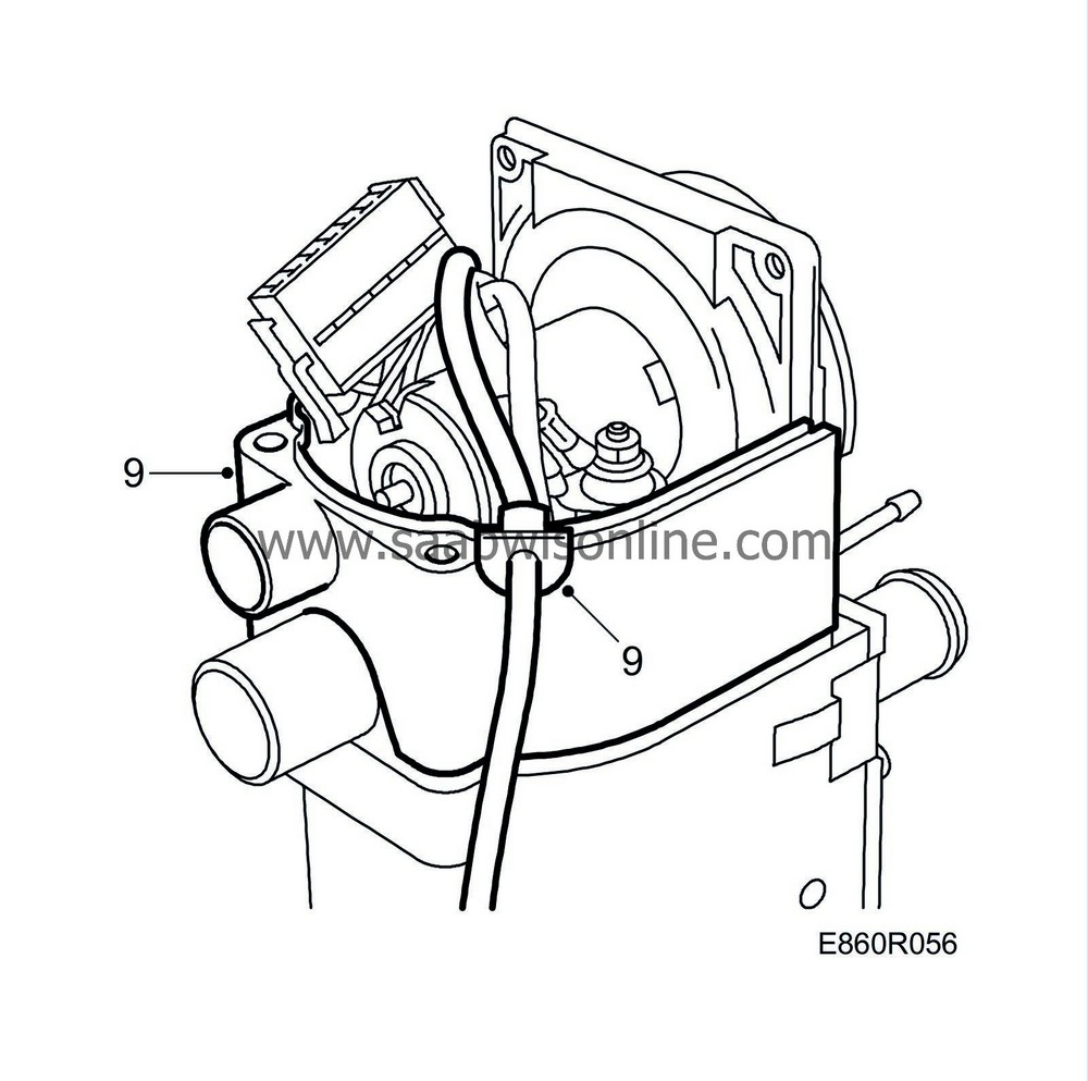
| 9. |
Fit the centre housing.
|
|
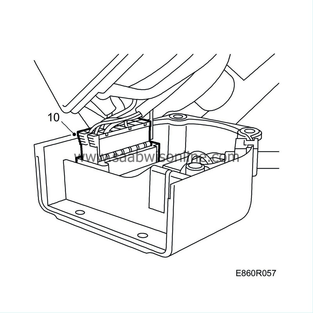
| 10. |
Plug connector B2 into the control module.
|
|
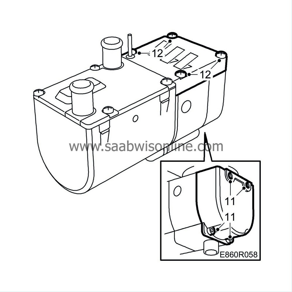
| 11. |
Fit the control module.
|
|
| 12. |
Fit the cover.
|
|||||||


