Crankshaft and pistons, removal
| Crankshaft and pistons, removal |
| To remove |
| 1. |
Remove the power unit. See Power unit removal.
|
|
| 2. |
Fit
32 025 020 Lifting eye
.
|
|
| 3. |
Remove the torque arm from the subframe and disconnect the electrical connections from the EHPS unit.
|
|
| 4. |
Lift the power unit off of the subframe using
83 92 409 Lifting yoke
.
|
|
| 5. |
Detach the electrical connections from the starter motor and generator. Detach the wiring harness from the engine.
|
|
| 6. |
Remove the starter motor.
|
|
| 7. |
Remove the bracket of the front catalytic converter.
|
|
| 8. |
Aut
: Undo the 6 bolts holding the torque converter to the driver plate. Turn the engine clockwise at the pulley's centre bolt.
Remove the gearbox oil cooling hoses and plug the holes and hoses with 82 92 955 Plugs, spare part kit . |
|
| 9. |
Man
: Remove the gearbox bolts and lift it from the engine.
|
|
| 10. |
Aut
: Remove the gearbox bolts. Pull the gearbox out approx. 10 mm.
Loosen the plug, press the torque converter toward the gearbox and fit 87 92 574 Holder to hold the torque converter in place. Remove the gearbox. |
|
| 11. |
Remove the pipe of the coolant reservoir.
|
|
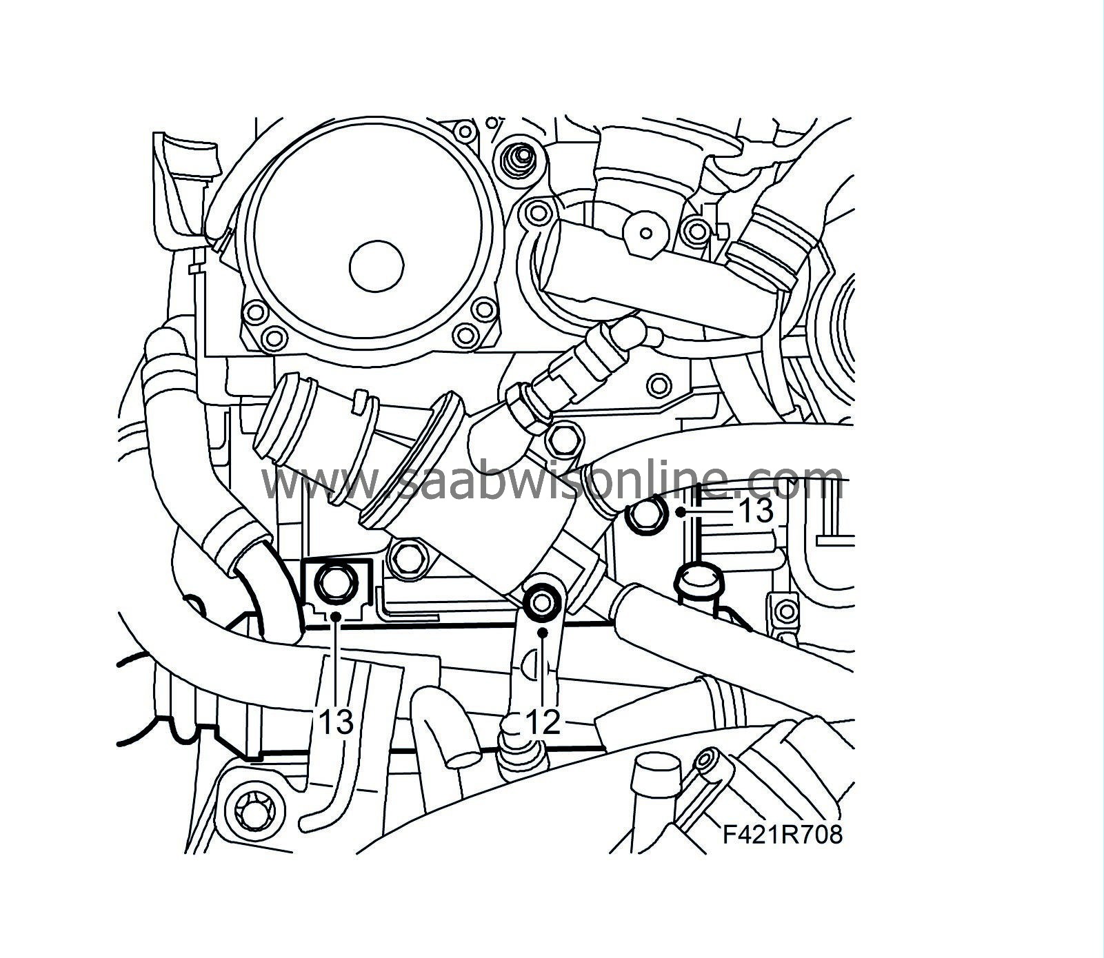
| 12. |
Detach the coolant pipes that run to the oil cooler.
|
|
| 13. |
Remove the EGR cooler assembly.
|
|
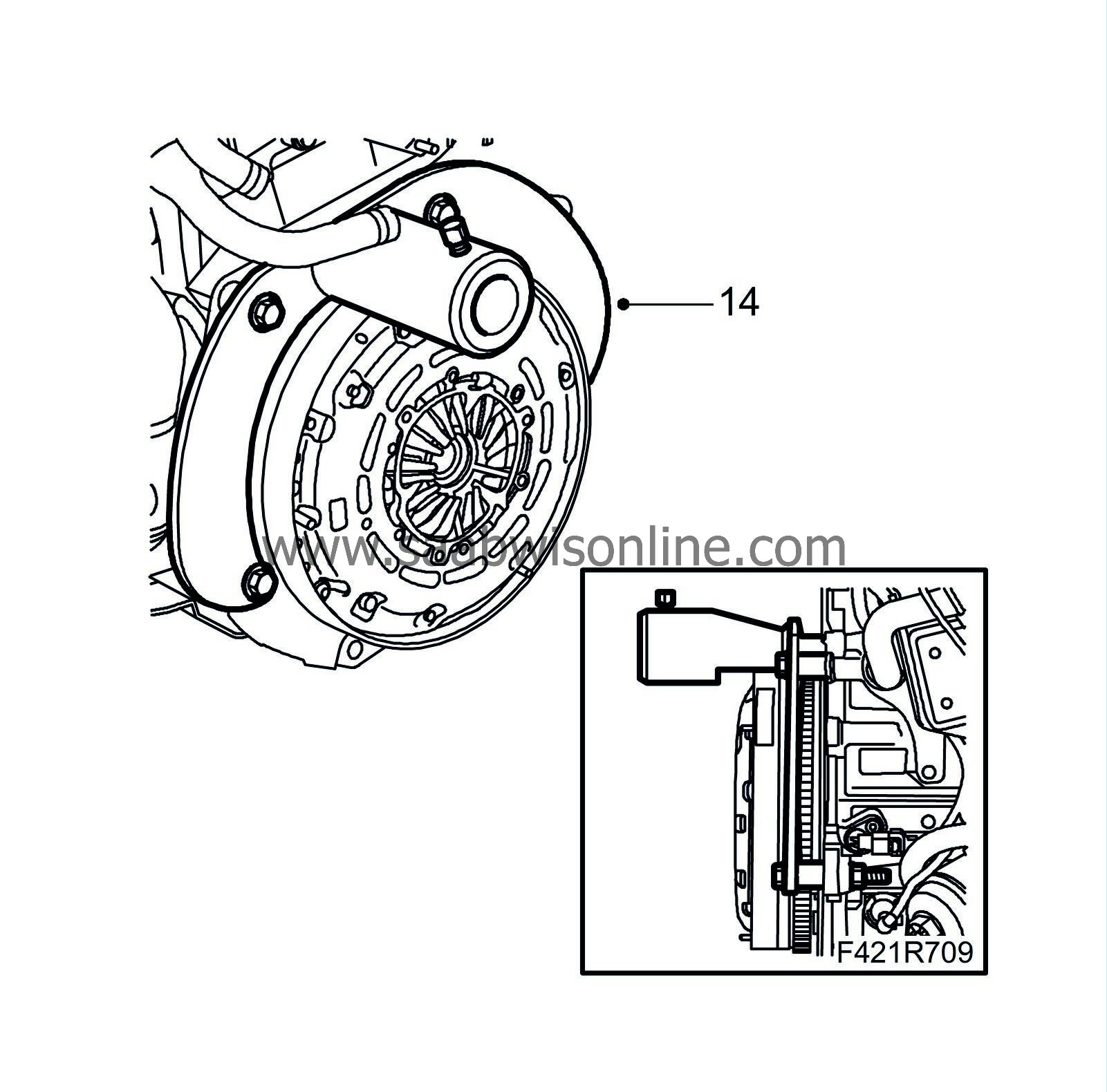
| 14. |
Fit
32 025 017 Holder, engine in stand
and
83 96 376 Adapter kit, 4 sleeves
. Fit the engine to
78 74 878 Floor stand
.
|
|
| 15. |
Drain the engine oil. Remove the oil filter cover and filter.
|
|
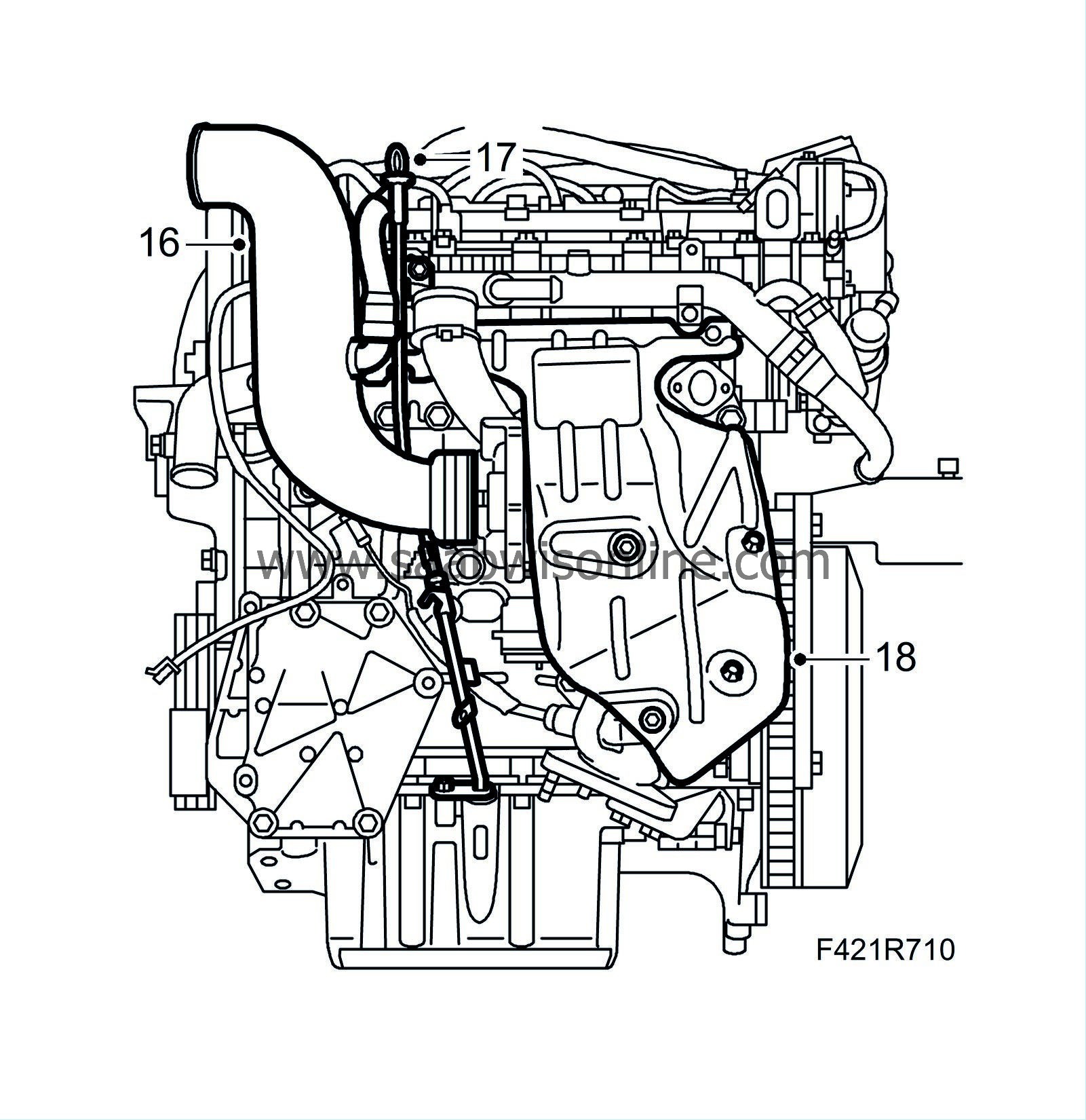
| 16. |
Detach the intake manifold from the turbocharger.
|
|
| 17. |
Remove the dipstick guide tube.
|
|
| 18. |
Remove the heat shield.
|
|
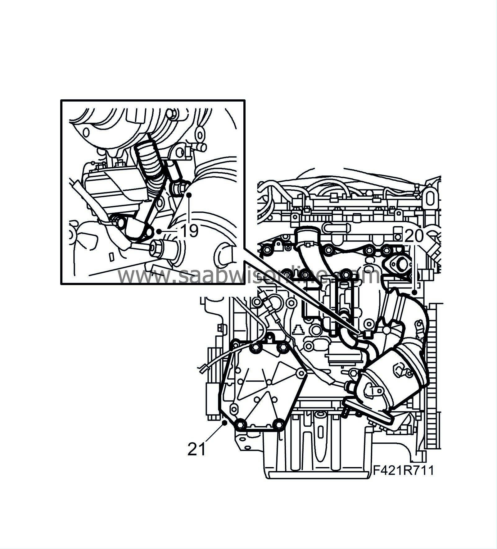
| 19. |
Remove the turbocharger oil delivery line and return line from the engine block.
|
|
| 20. |
Remove the turbocharger with catalytic converter.
|
|
| 21. |
Remove the A/C bracket.
|
|
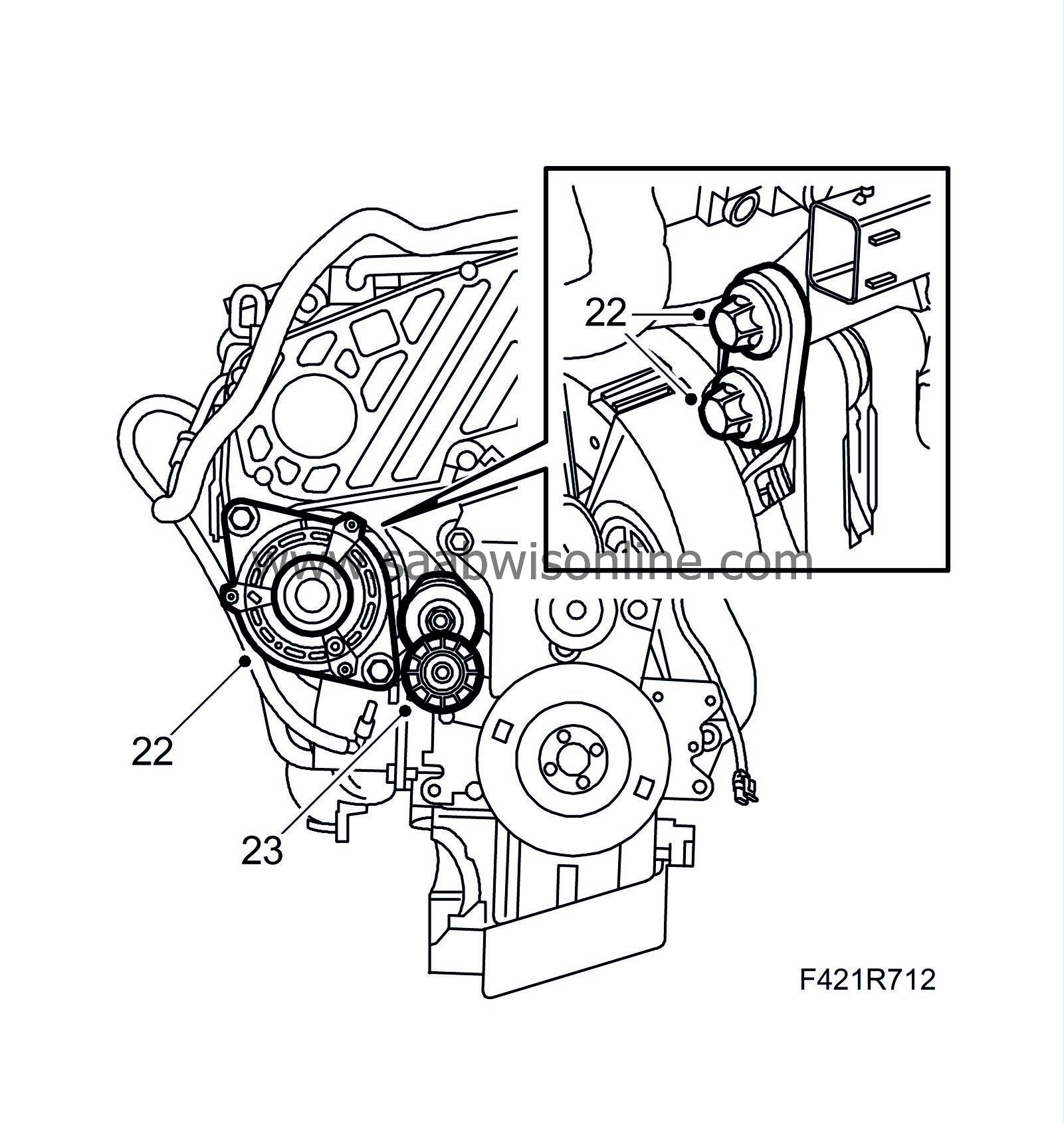
| 22. |
Remove the generator.
|
|
| 23. |
Remove the belt tensioner.
|
|
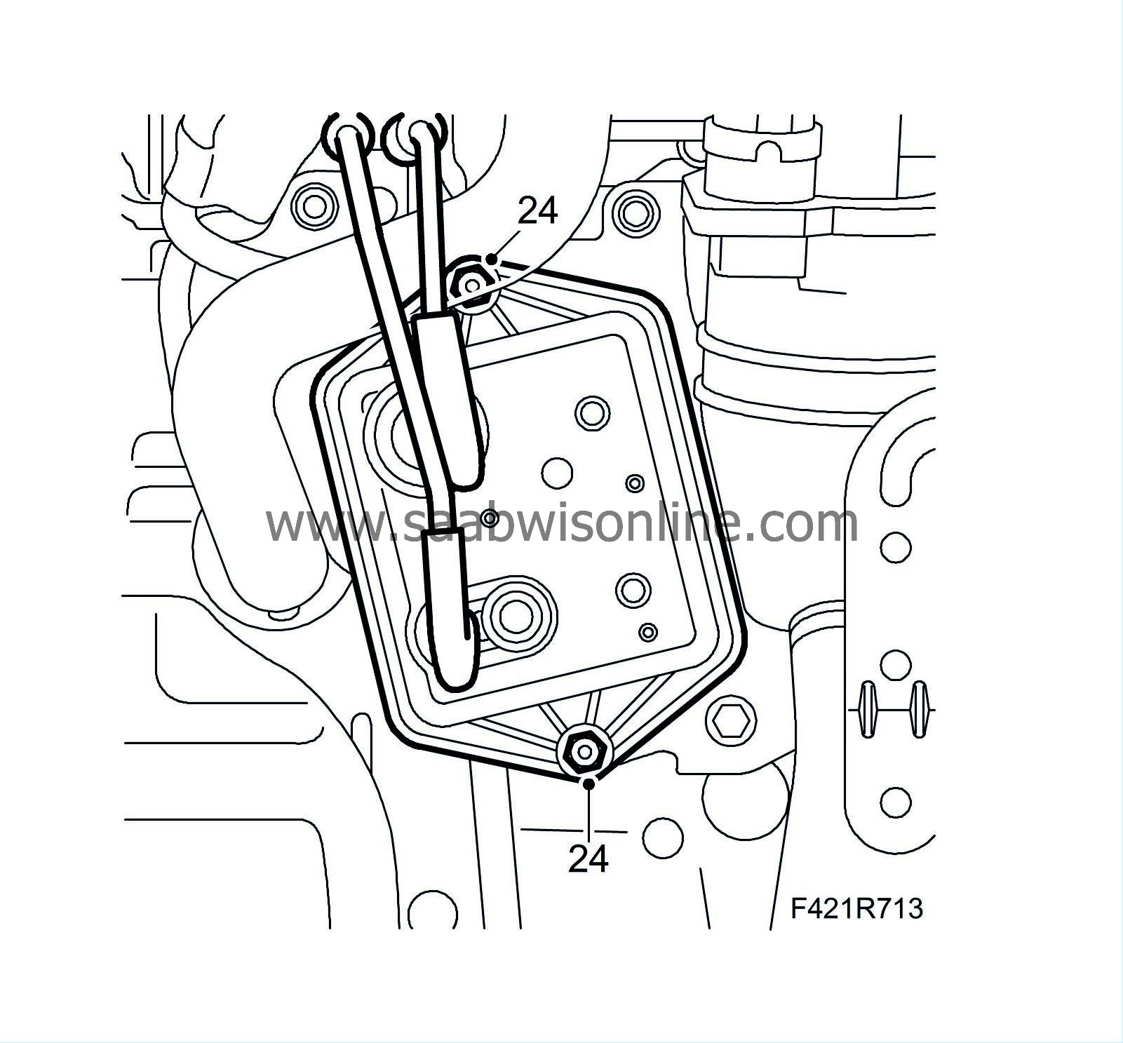
| 24. |
Remove the vacuum reservoir.
|
|
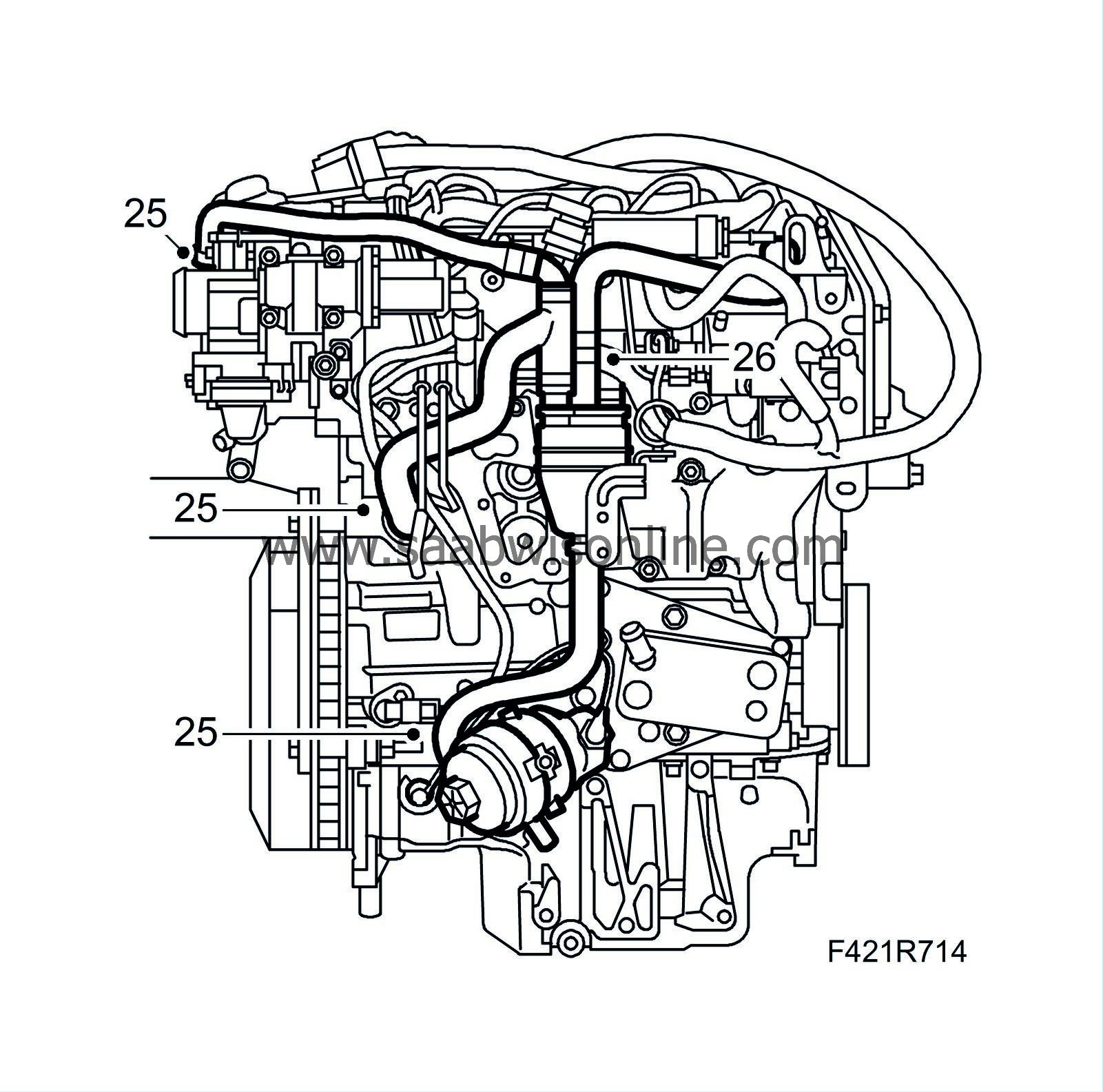
| 25. |
Detach the crankcase ventilation hoses from the engine, oil sump and oil filler port.
|
|
| 26. |
Detach the oil trap hoses with quick coupling.
|
|
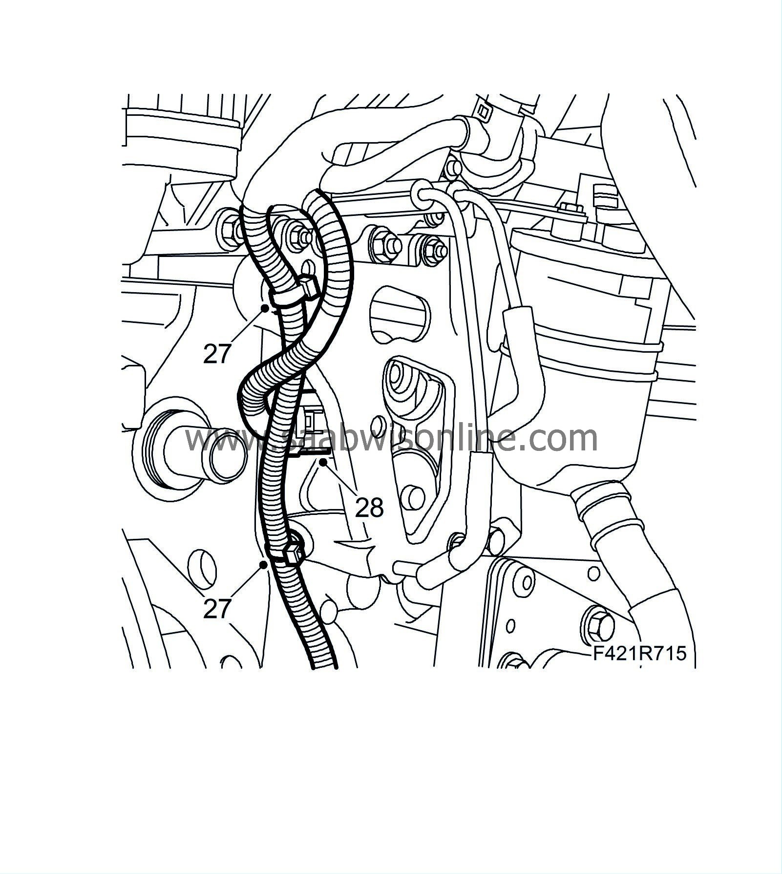
| 27. |
Detach the wiring harness from the mounting.
|
|
| 28. |
Unplug the combustion circulation connection (403).
|
|
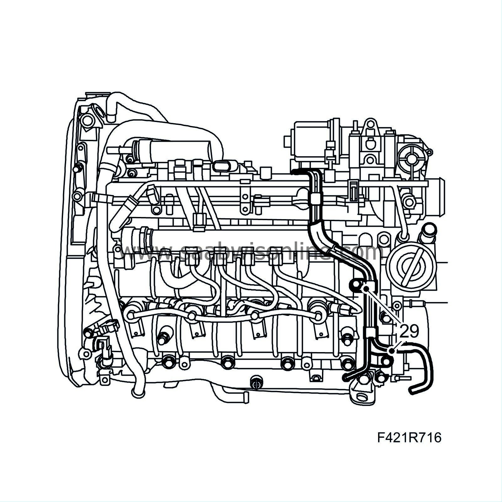
| 29. |
Detach the vacuum pipe.
|
|
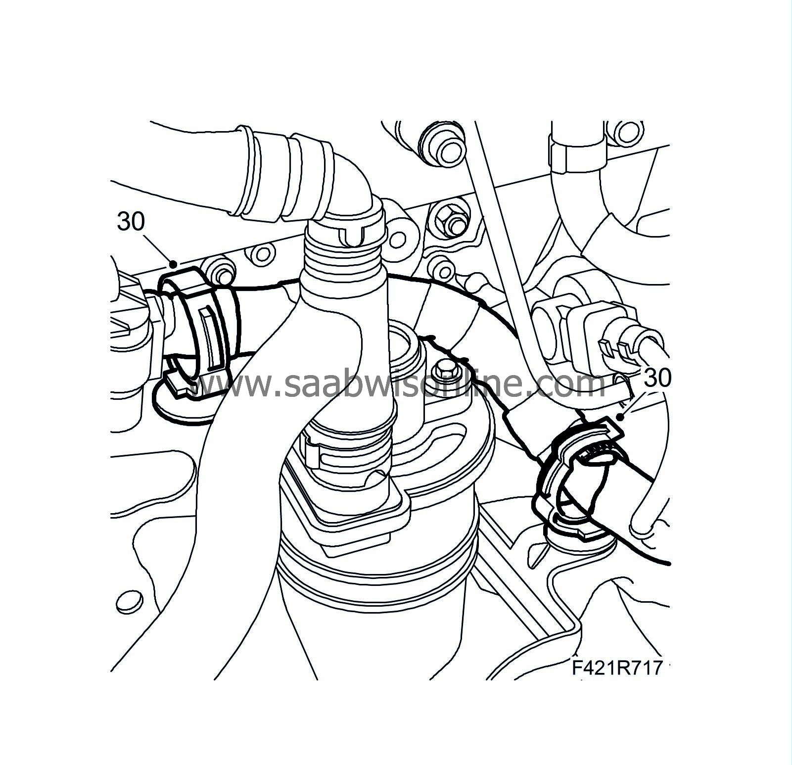
| 30. |
Open the wiring harness clips.
|
|
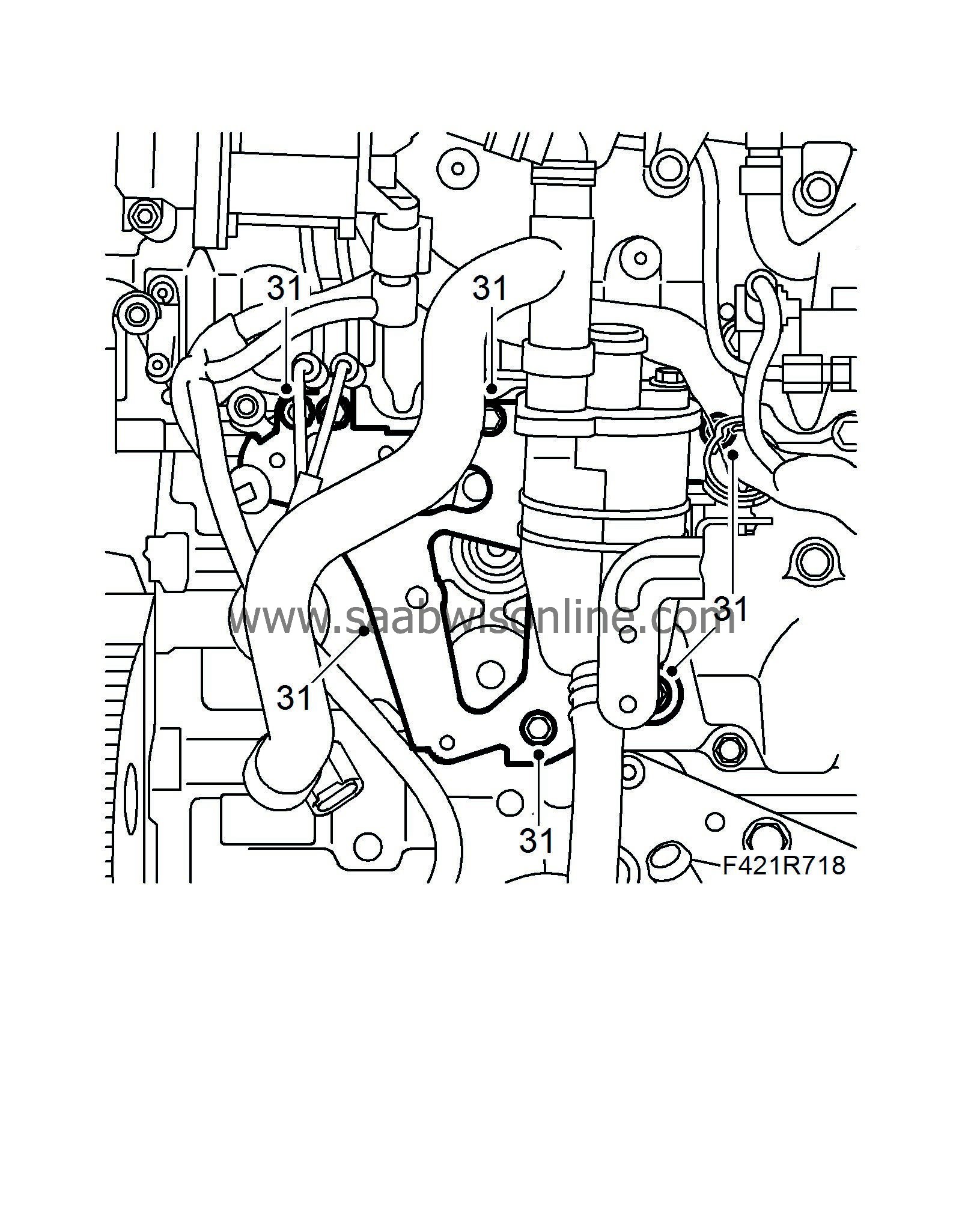
| 31. |
Remove the oil trap mounting.
|
|
| 32. |
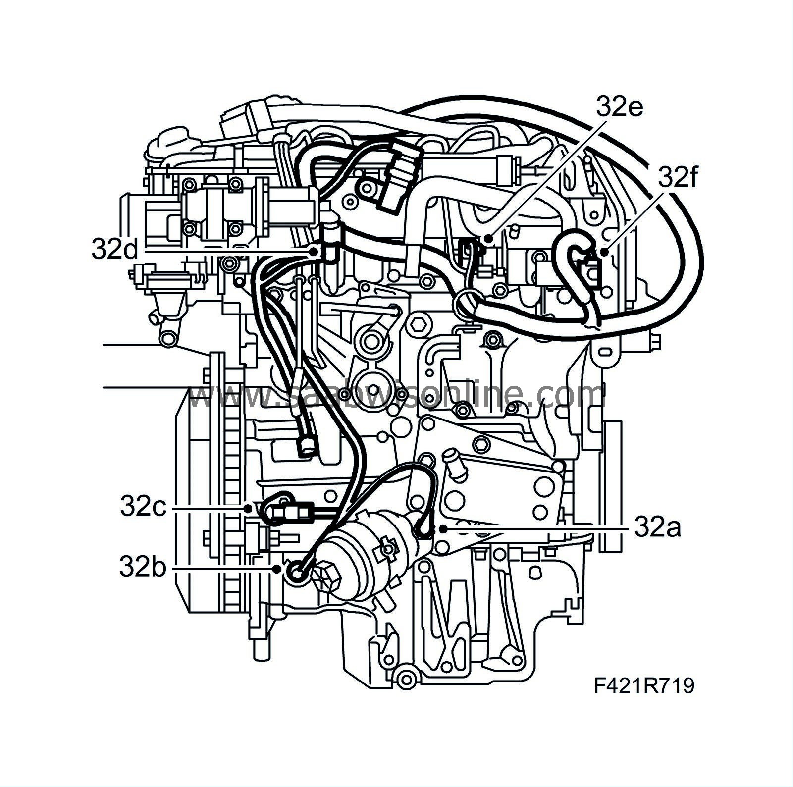
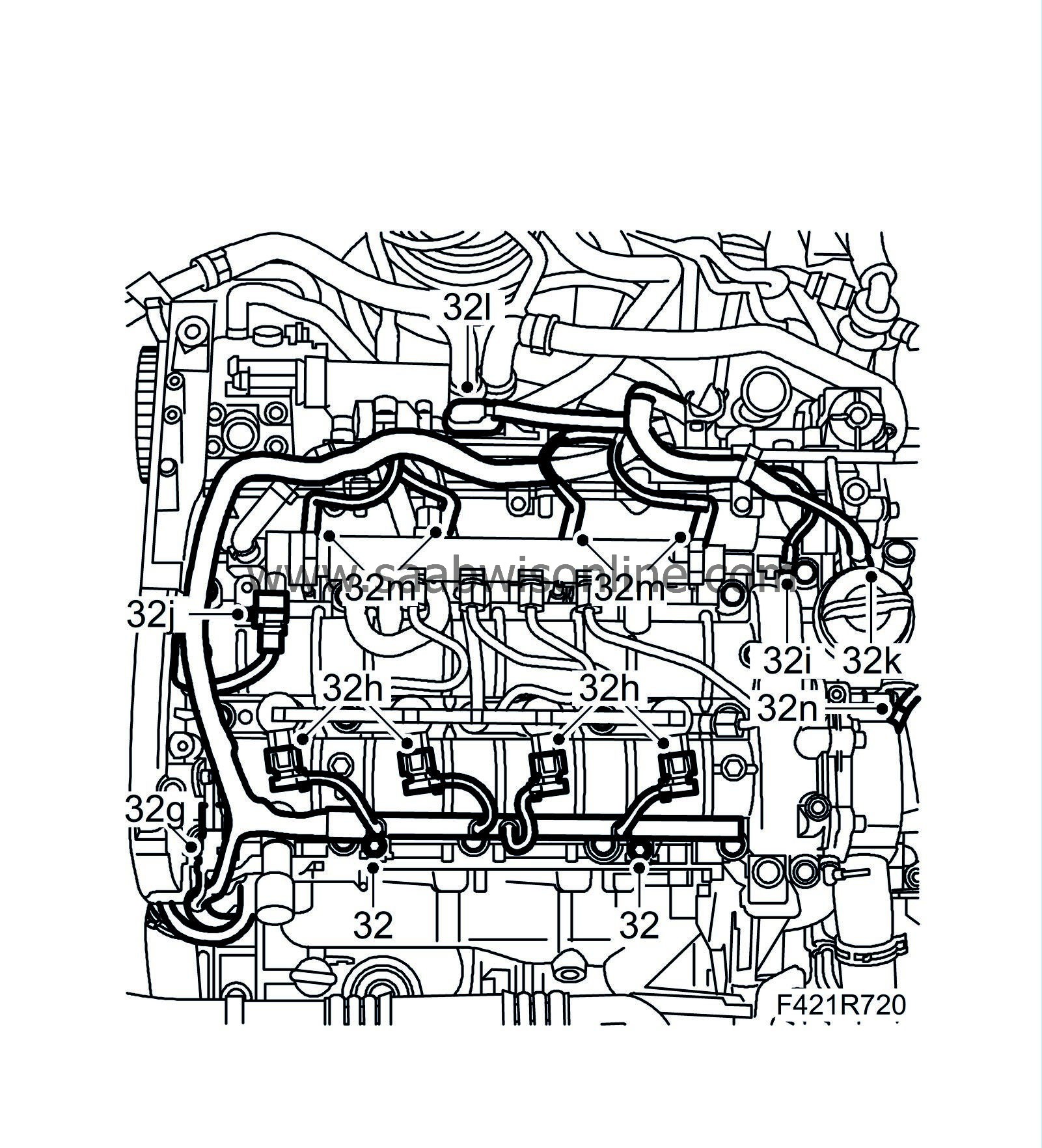
Detach the engine wiring harness by unplugging the following connectors:
|
|
| 32.a. |
Engine oil pressure switch (44)
|
| 32.b. |
Level switch, engine oil (243)
|
| 32.c. |
Crankshaft position sensor (345)
|
| 32.d. |
EGR solenoid valve (606)
|
| 32.e. |
Fuel quantity solenoid valve, high pressure pump (652b)
|
| 32.f. |
Connector H11-1
|
| 32.g. |
Camshaft position sensor (555).
|
| 32.h. |
Injectors (206).
|
| 32.i. |
Fuel pressure sensor (653).
|
| 32.j. |
Fuel pressure solenoid valve (652a).
|
| 32.k. |
Electronic throttle actuator (604).
|
| 32.l. |
Intake air sensor (688).
|
| 32.m. |
Glow plug connector.
|
| 32.n. |
Coolant temperature sensor (202).
|
| 33. |
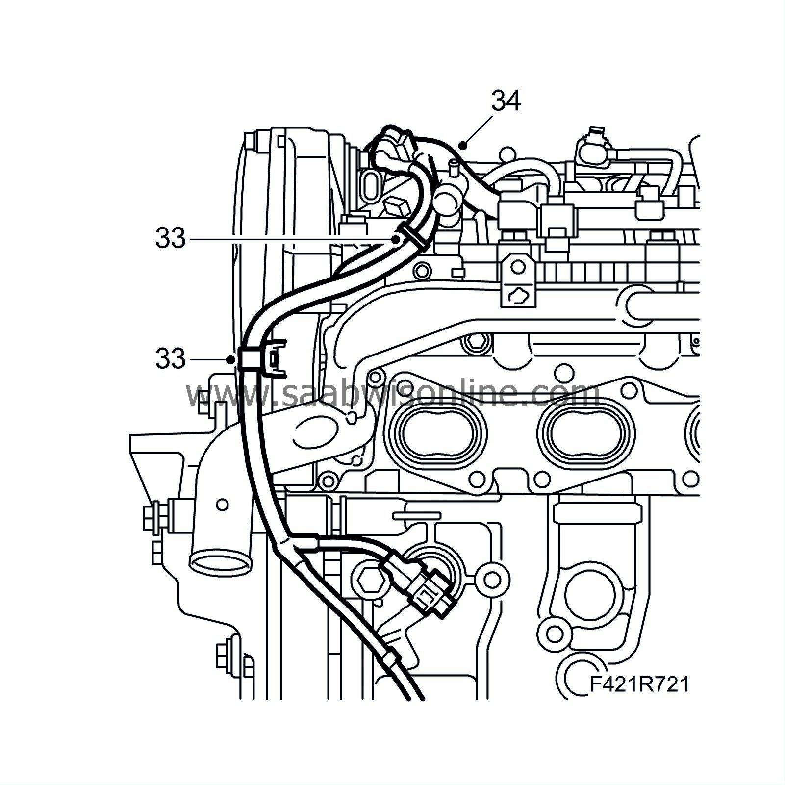
Remove the wiring harness clips (front side).
|
|
| 34. |
Lift away the wiring harness.
|
|
| 35. |
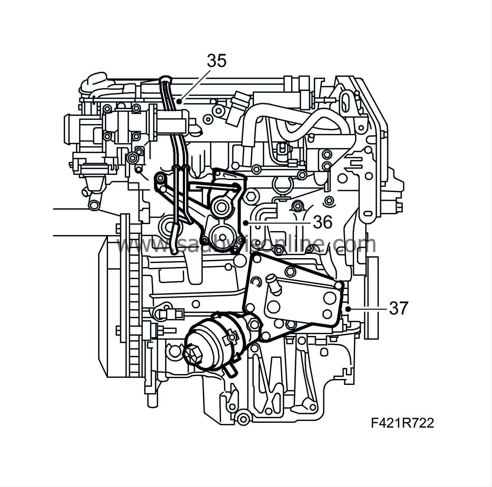
Detach the vacuum pipe.
|
|
| 36. |
Remove the combustion circulation actuator (403).
|
|
| 37. |
Remove the oil cooler assembly with oil filter housing.
|
|
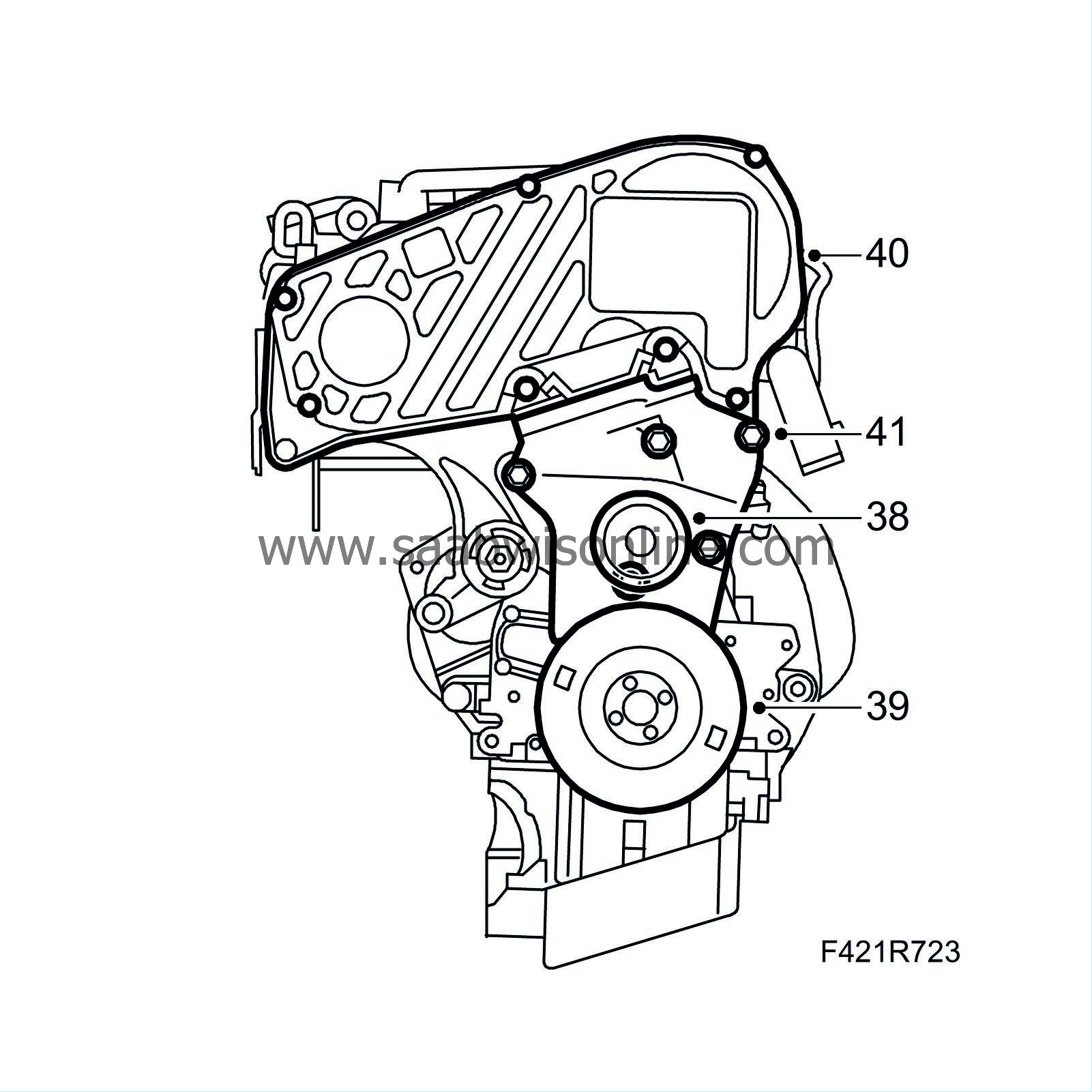
| 39. |
Remove the crankshaft pulley.
|
|
| 40. |
Remove the upper timing cover.
|
|
| 41. |
Remove the lower timing cover.
|
|
| 42. |
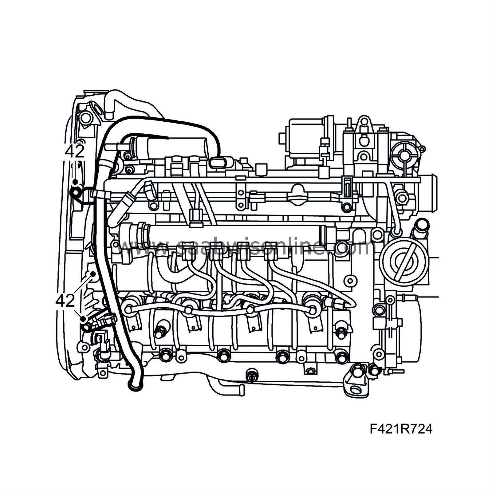
Detach the crankcase ventilation pipe and hose from the camshaft housing.
|
|
| 43. |
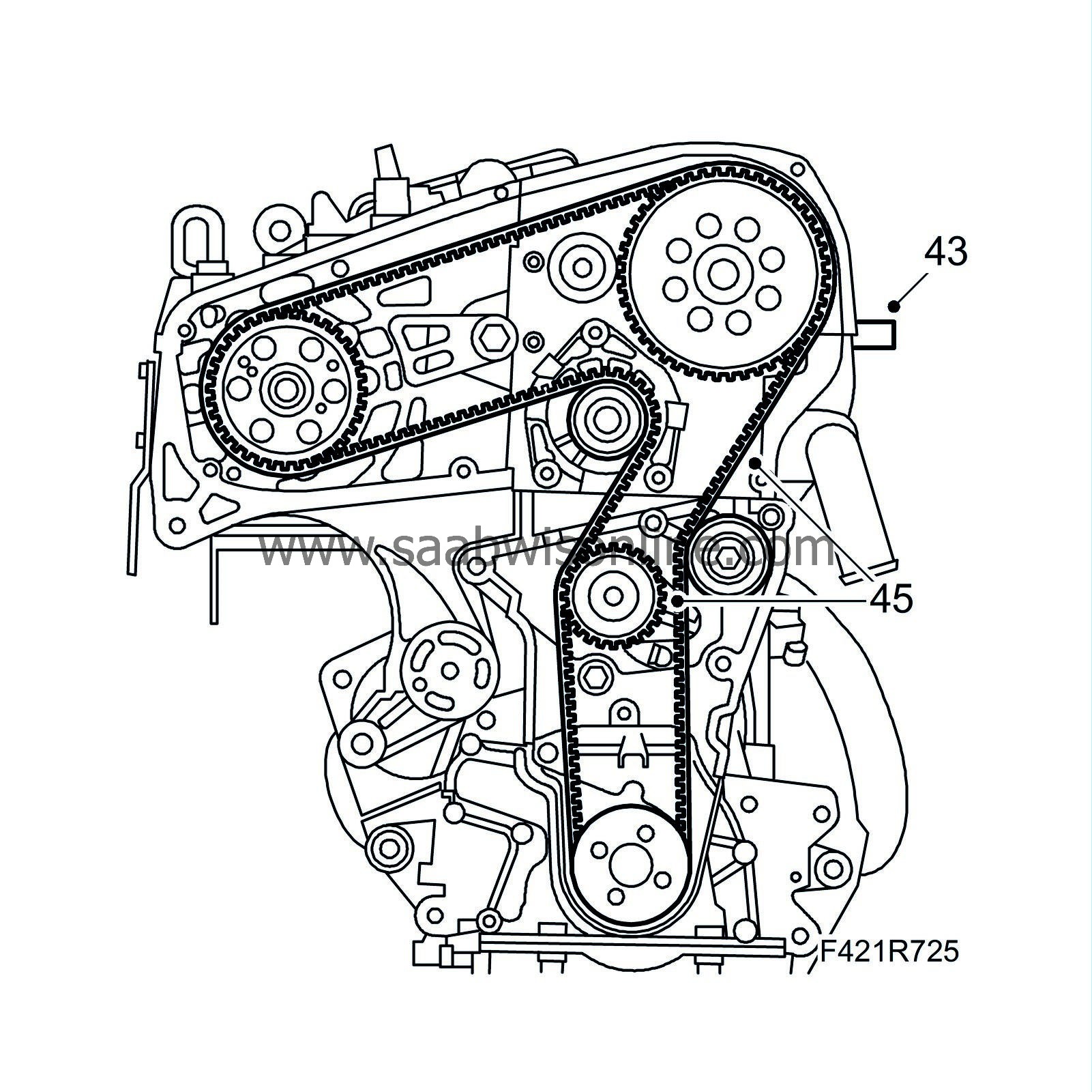
Reset the engine by removing the plug and fitting
32 025 008 Camshaft fixing tool
.
|
|
| 44. |
Turn the engine until the tool clicks and locks the exhaust camshaft.
|
|
| 45. |
Relieve tension in the belt tensioner and remove the timing belt.
Mark the direction of rotation if the timing belt is to be refitted. |
|
| 46. |
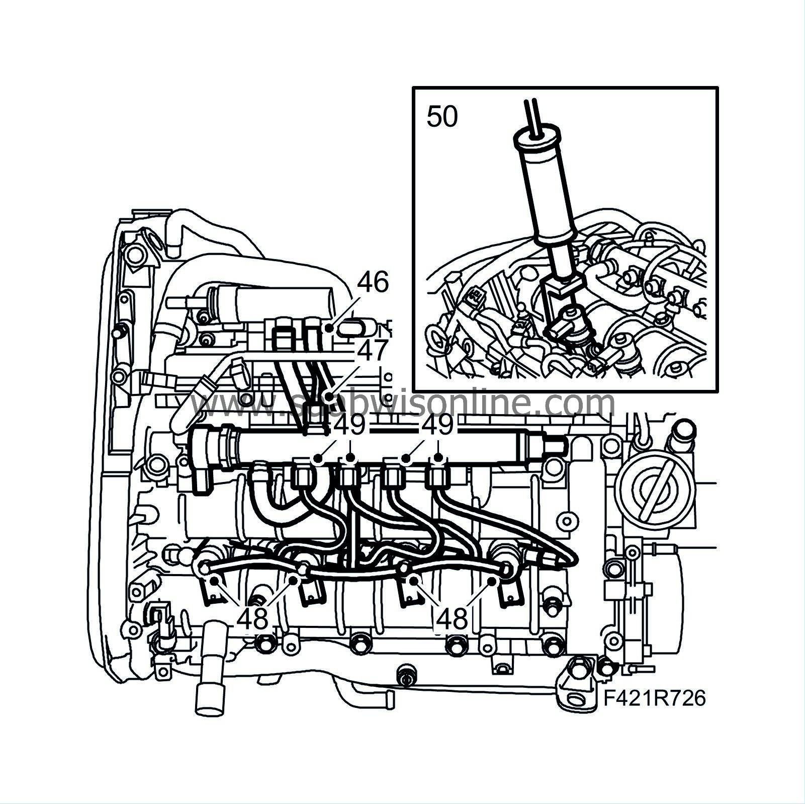
Detach the return fuel hose from the return fuel tank.
|
|
| 47. |
Detach the fuel delivery pipe between the pump and fuel rail.
|
|
| 48. |
Detach the return fuel hoses.
|
|
| 49. |
Detach the fuel pipes from the injectors and fuel rail. Use a wrench to counterhold at the injector when removing the pipe. Mark the pipes to facilitate refitting.
|
||||||||||
| 50. |
Remove the injector with holder. If the nozzles cannot be raised by hand, use
32 025 013 Injector removal tool
using 8
83 90 270 Sliding hammer
and
32 025 012 Sliding hammer adapter
. Remove the injectors in the following order: 1-2-3-4.
|
|
| 51. |
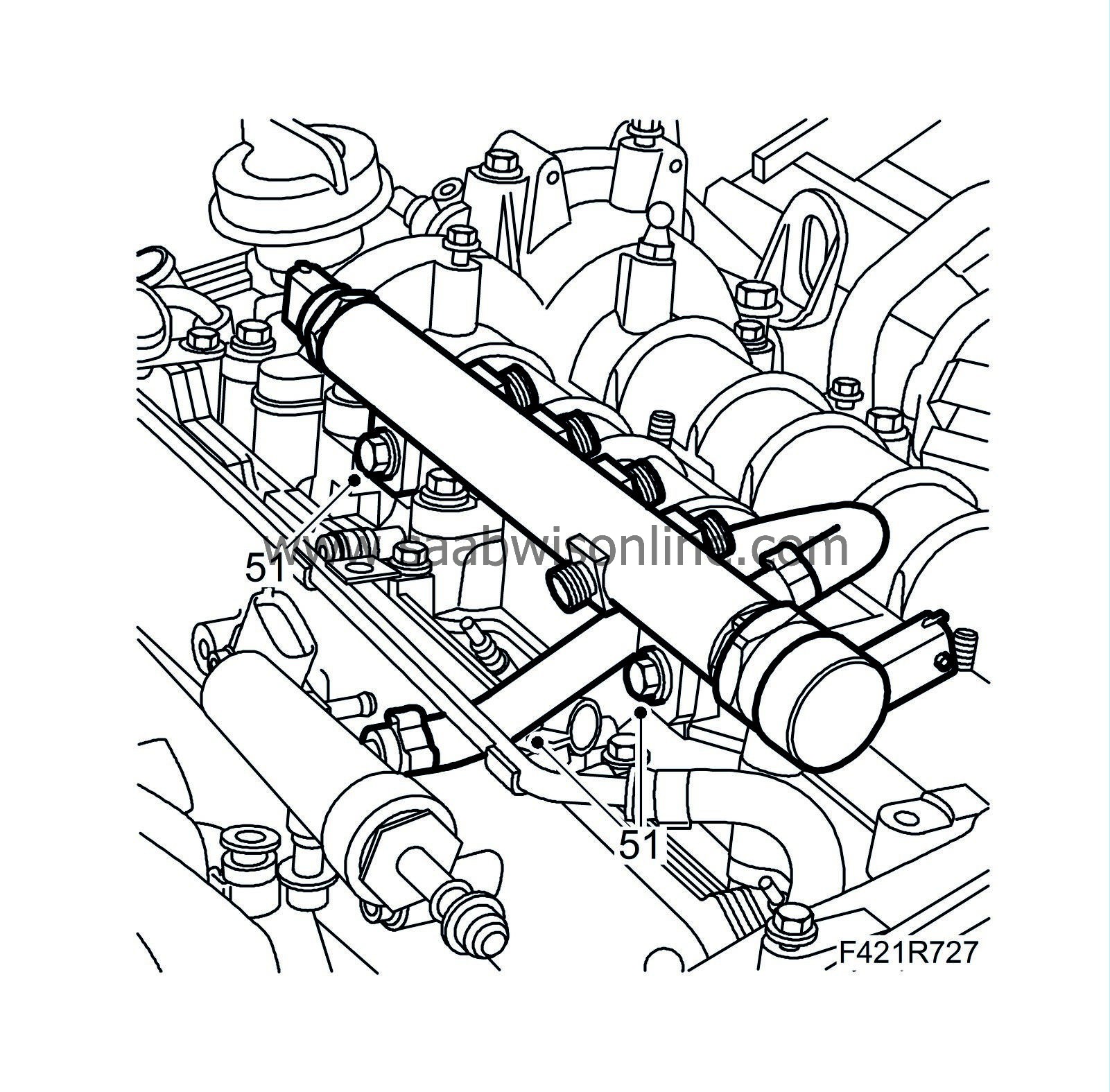
Remove the fuel rail and hose.
|
|
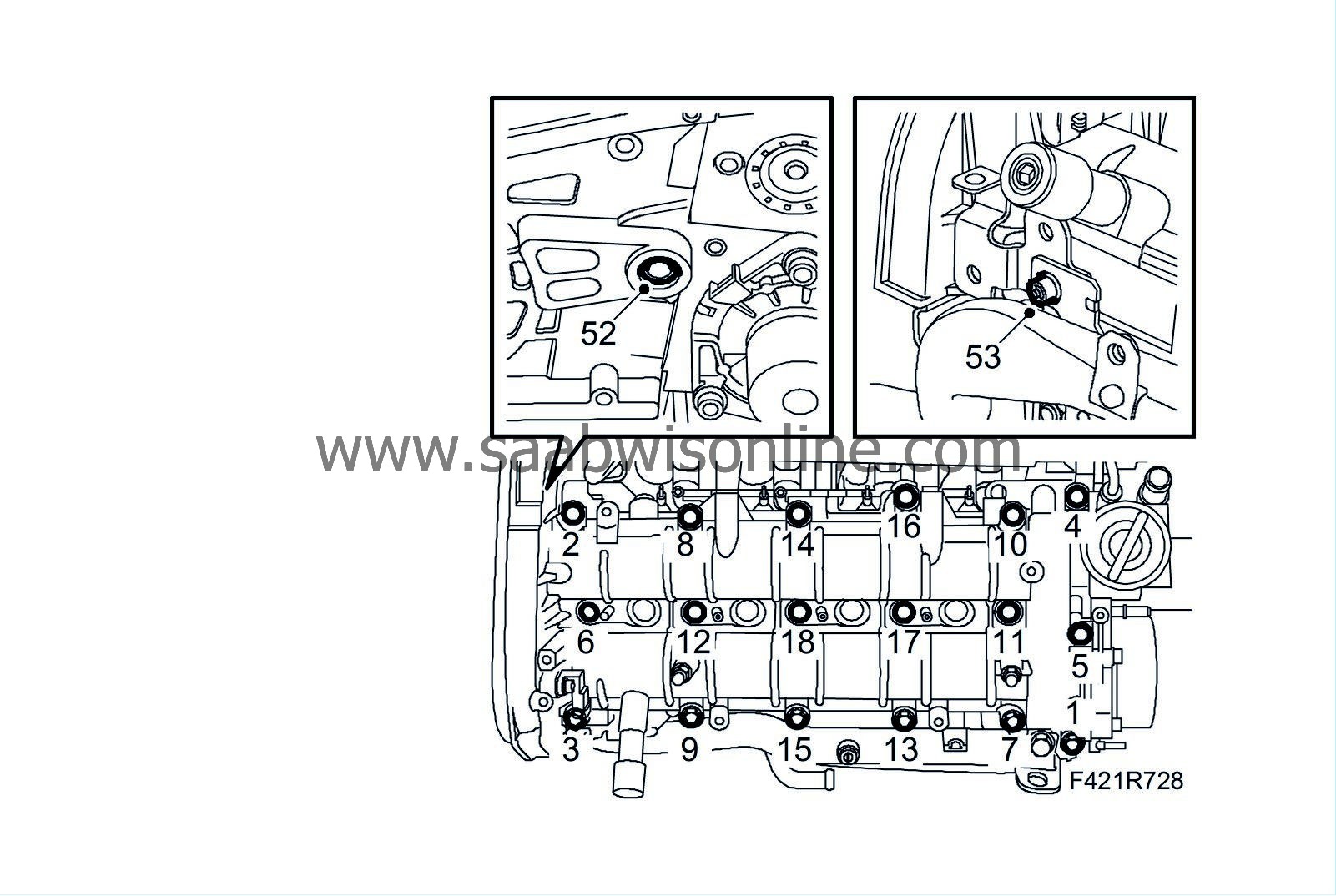
| 52. |
Remove the bolt between the fuel pump bracket and cylinder head. Slacken the spacer bolt a few turns.
|
|
| 53. |
Remove the mounting of the turbocharger intake manifold.
|
|
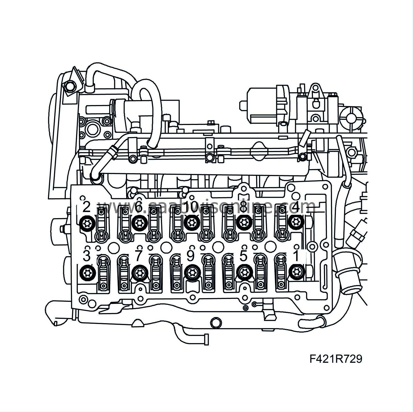
| 54. |
Loosen and remove the camshaft shaft housing and the guide sleeves. Remove in alternating order as illustrated.
|
|
| 55. |
Remove the cylinder head by undoing the bolts in the order illustrated.
|
|
| 56. |
Carefully lift off the cylinder head.
|
||||||||||
| 57. |
Remove the engine block guide sleeves.
|
|
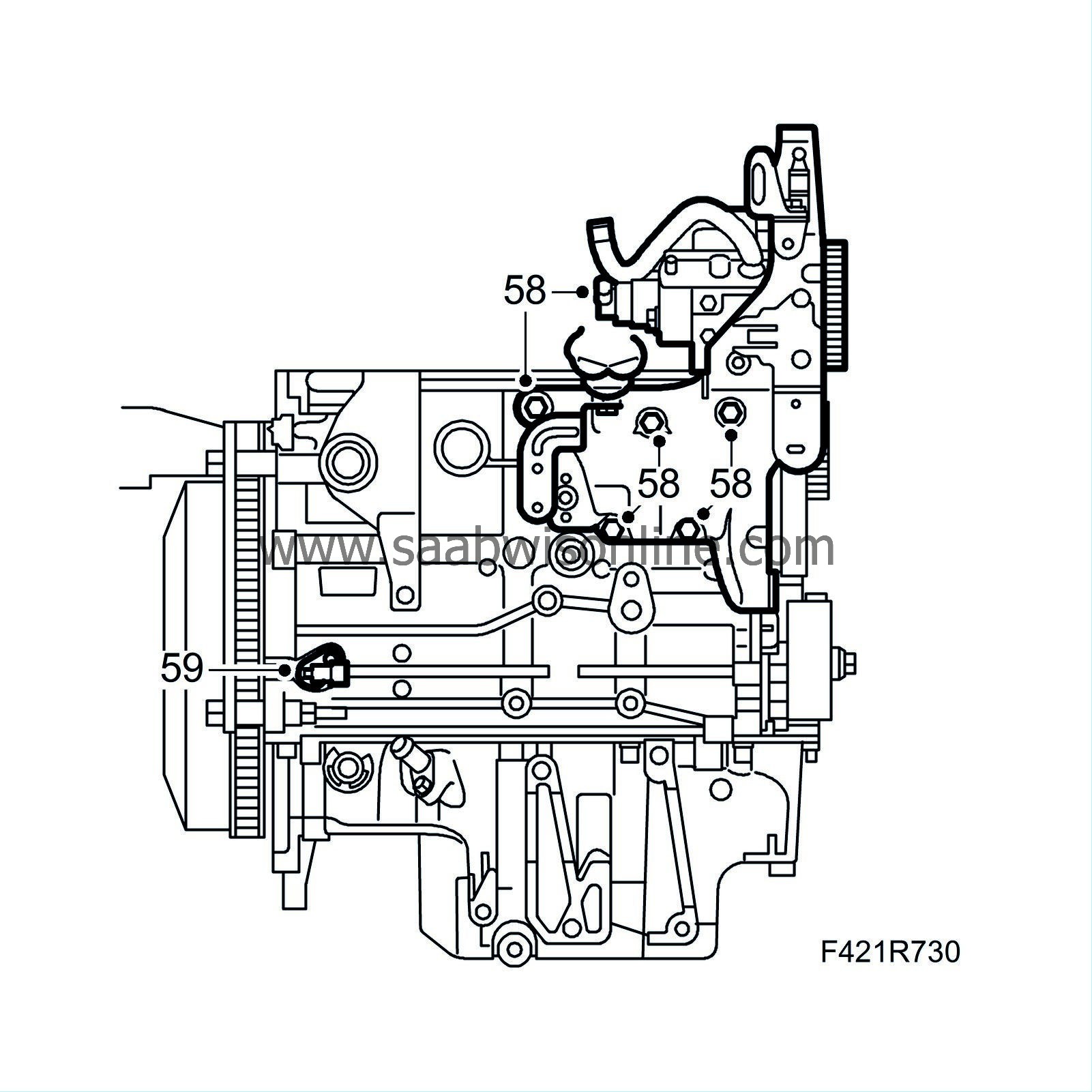
| 58. |
Remove the fuel pump mounting.
|
|
| 59. |
Remove the crankshaft position sensor.
|
|
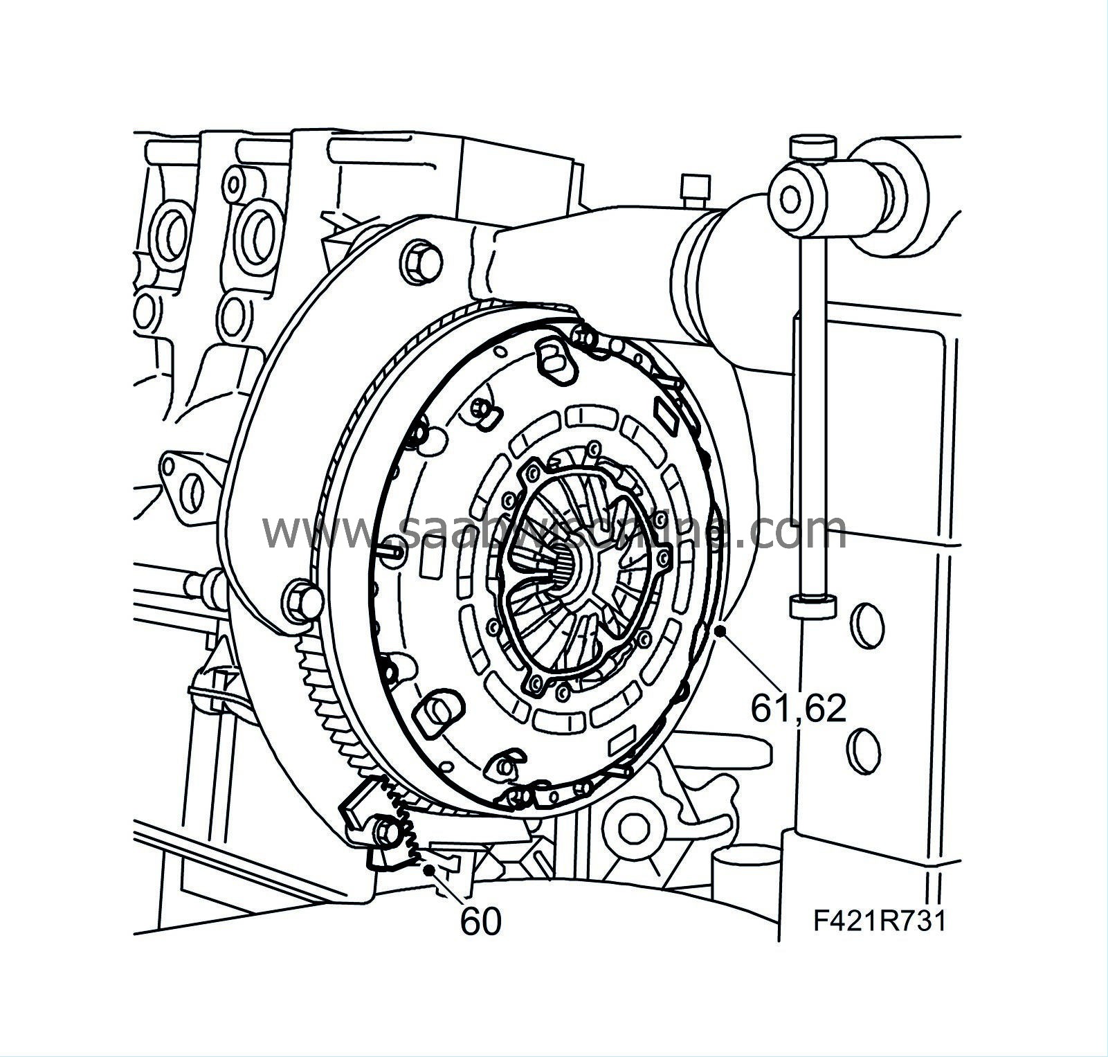
| 60. |
Fit
83 92 987 Flywheel locking attachment
in the threaded hole in the oil sump in order to lock the flywheel/driver plate in place.
|
|
| 61. |
Man
: Remove the bolts holding the pressure plate and remove the clutch.
|
|
| 62. |
Man
: Remove the clutch driven plate.
|
|
| 63. |
Remove the flywheel/driver plate.
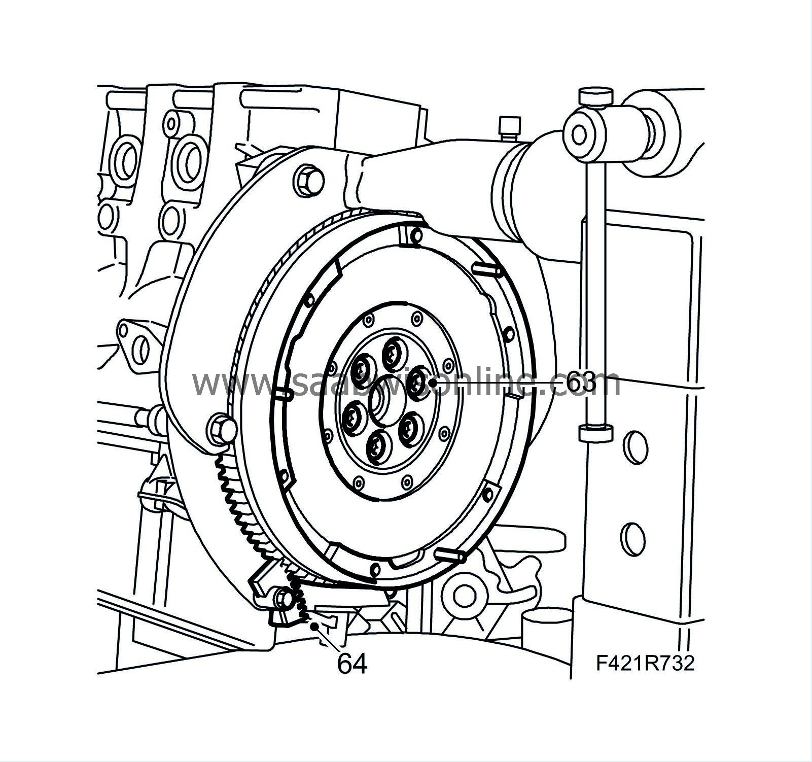
|
|
| 64. |
Remove the flywheel locking attachment.
|
|
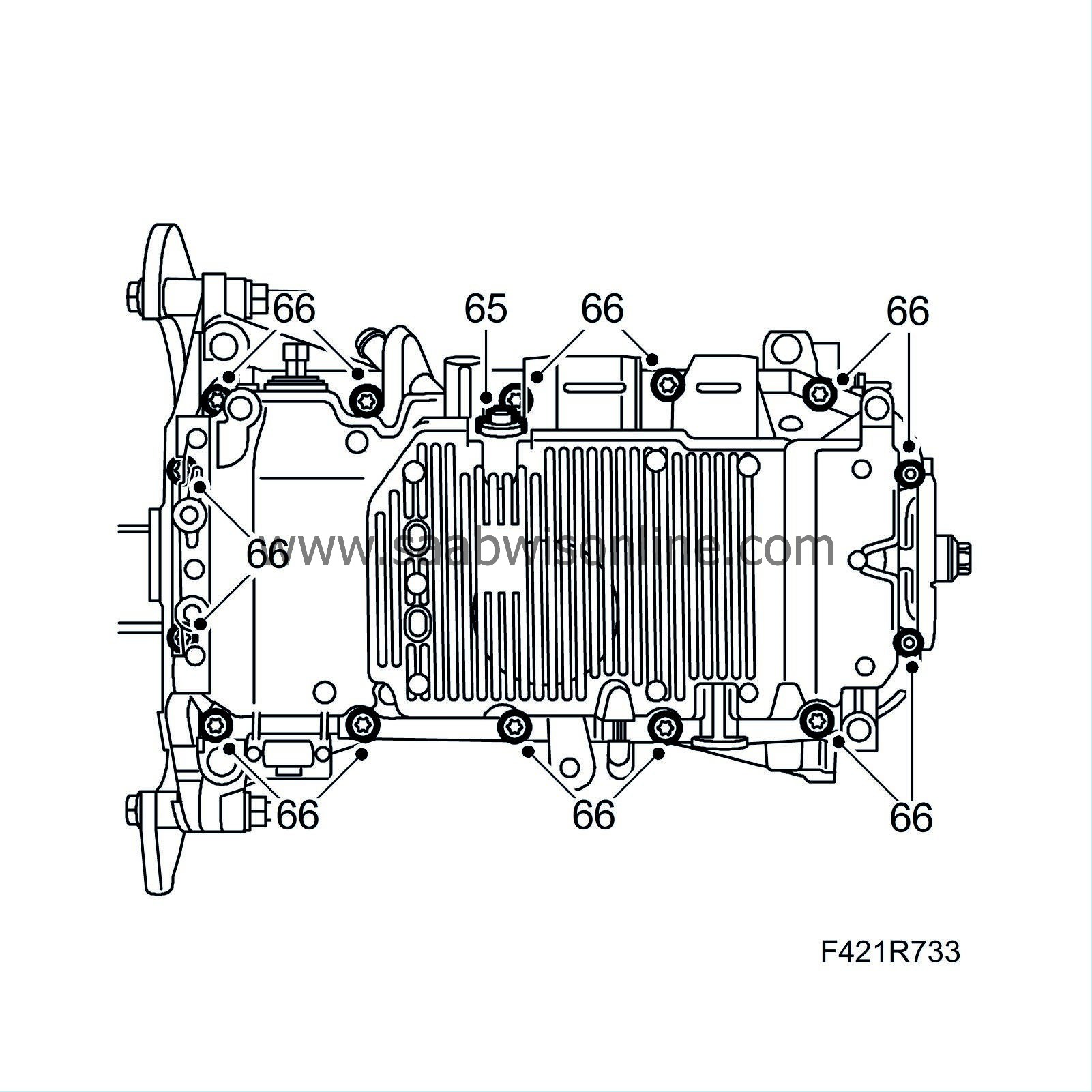
| 65. |
Replace the seal and fit the drain plug in the oil sump.
|
|
| 66. |
Remove the oil sump bolts using
32 025 015 Extension ribe M7
and
32 025 016 Extension ribe M8
.
|
|
| 67. |
Carefully prise loose the oil sump.
|
|
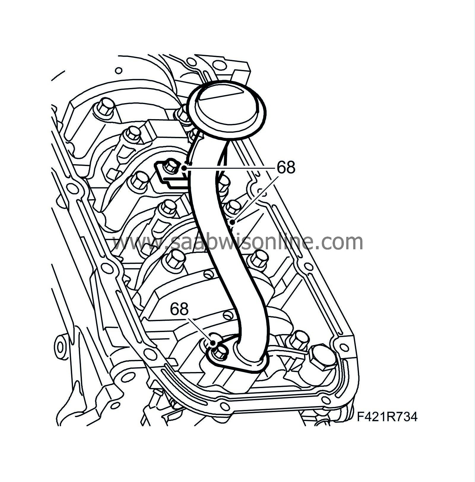
| 68. |
Remove the oil intake pipe.
|
|
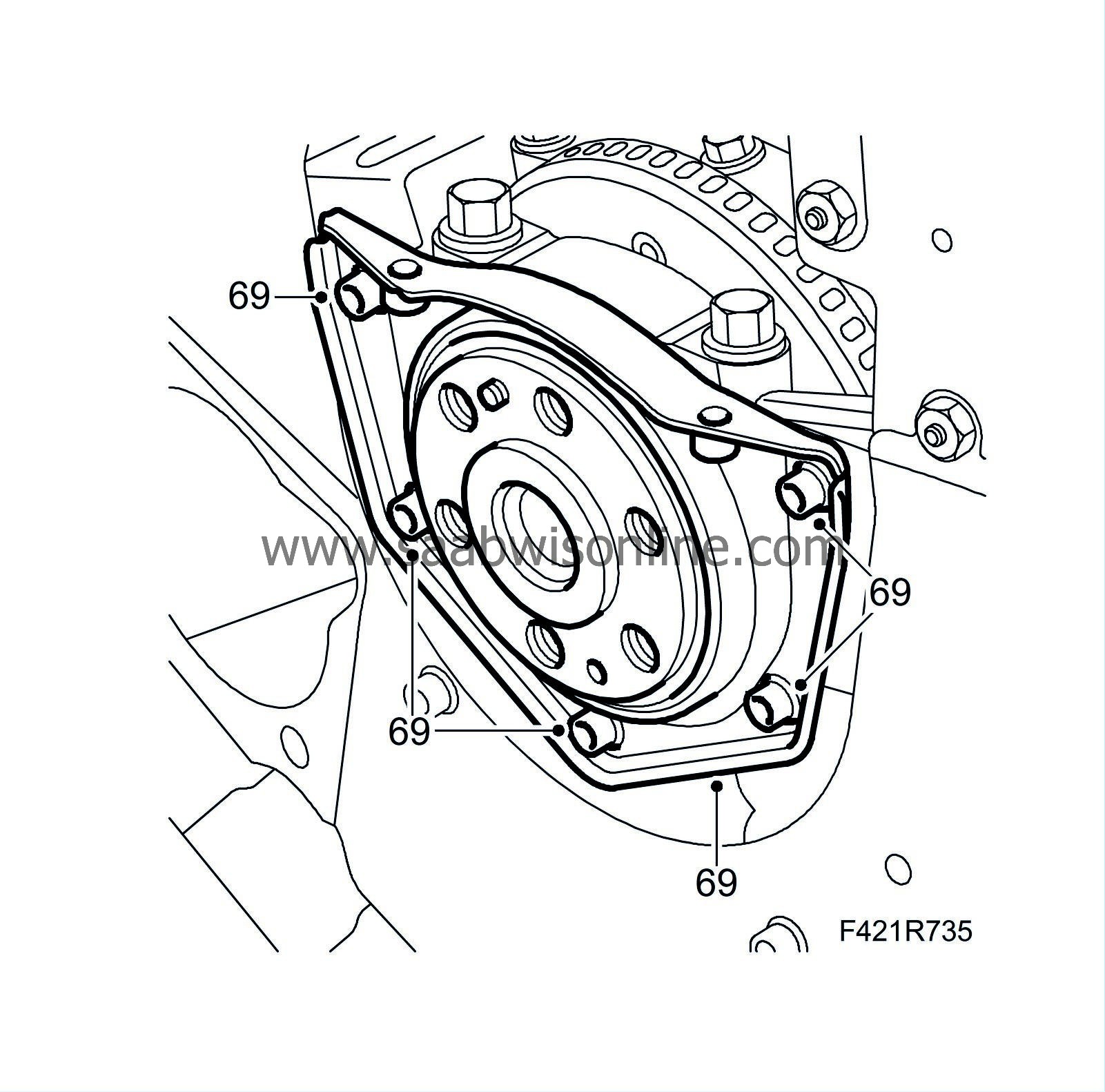
| 69. |
Remove the rear crankshaft seal.
|
|
| 70. |
Remove the belt pulley using
32 025 006 Crankshaft holder
(a) together with
83 95 360 Holding tool, crankshaft pulley
(b).
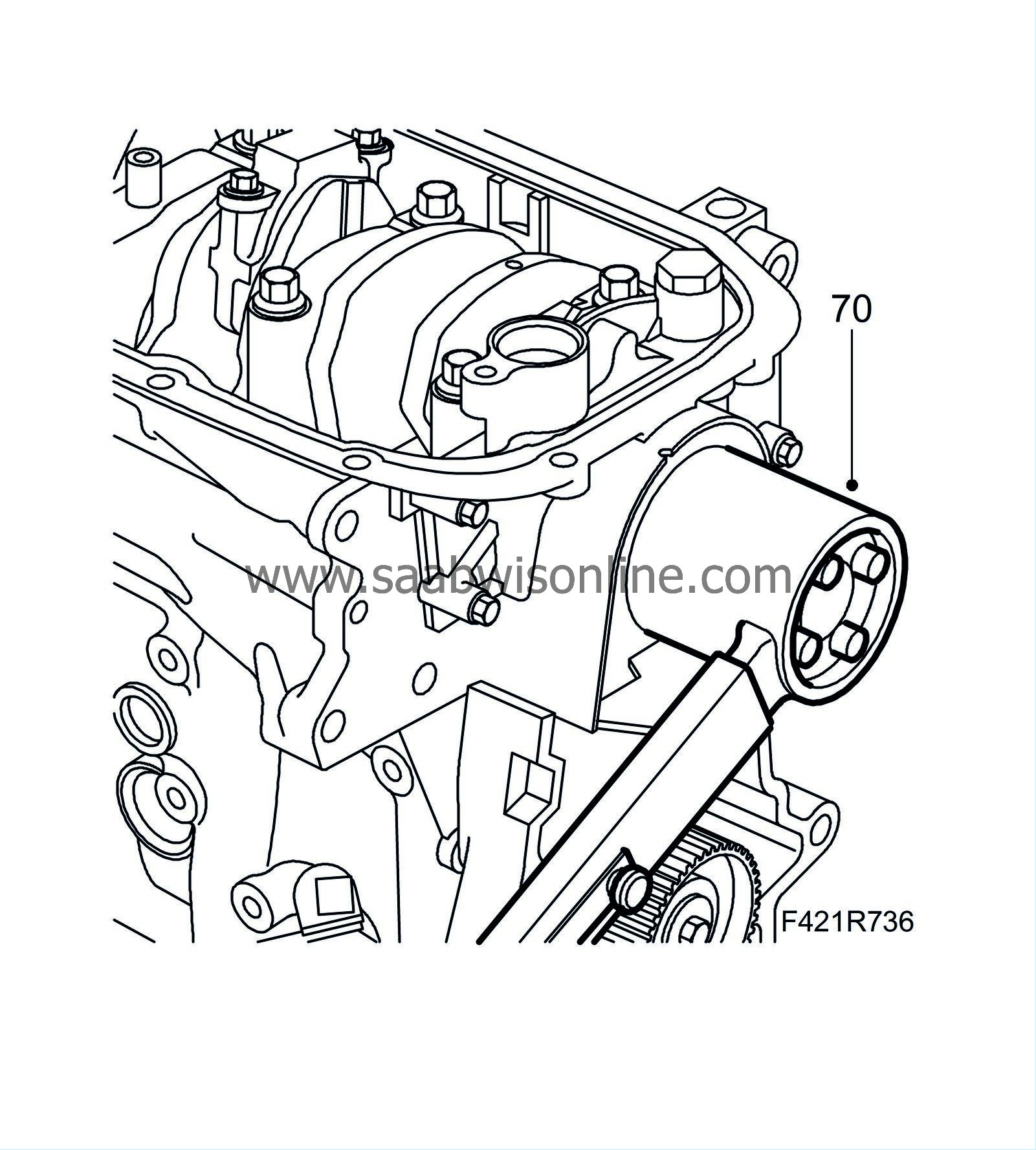
|
|||||||
| 71. |
Remove the oil pump.
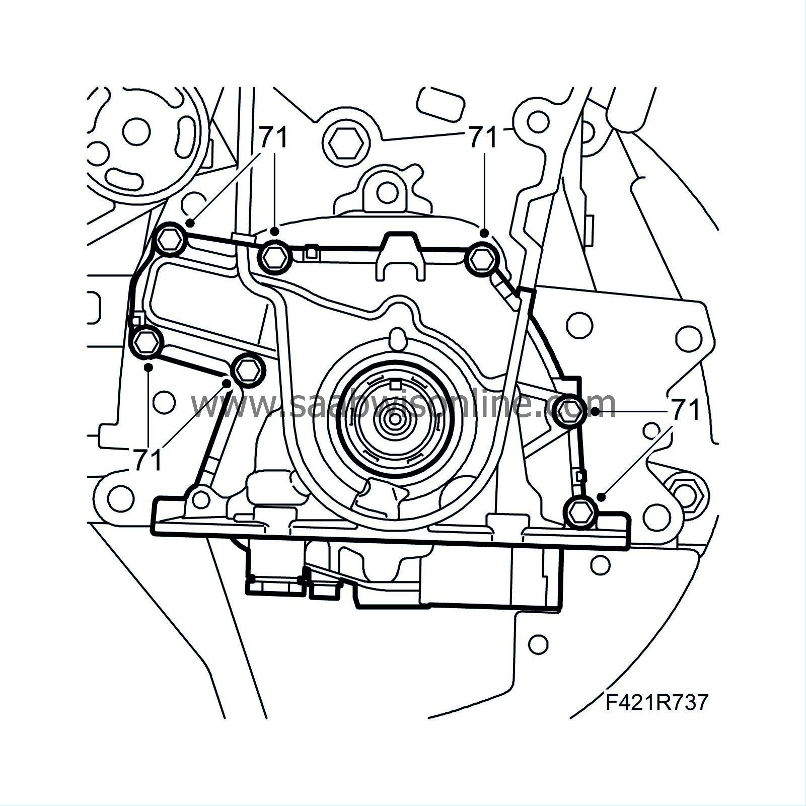
|
|
| 72. |
Note the marking on the connecting rods and bearing caps so that the can be refitted in their original spots. Remove the connecting rod bearing caps. Remove the pistons and connecting rods from the cylinder bore of cylinders 2 and 3.
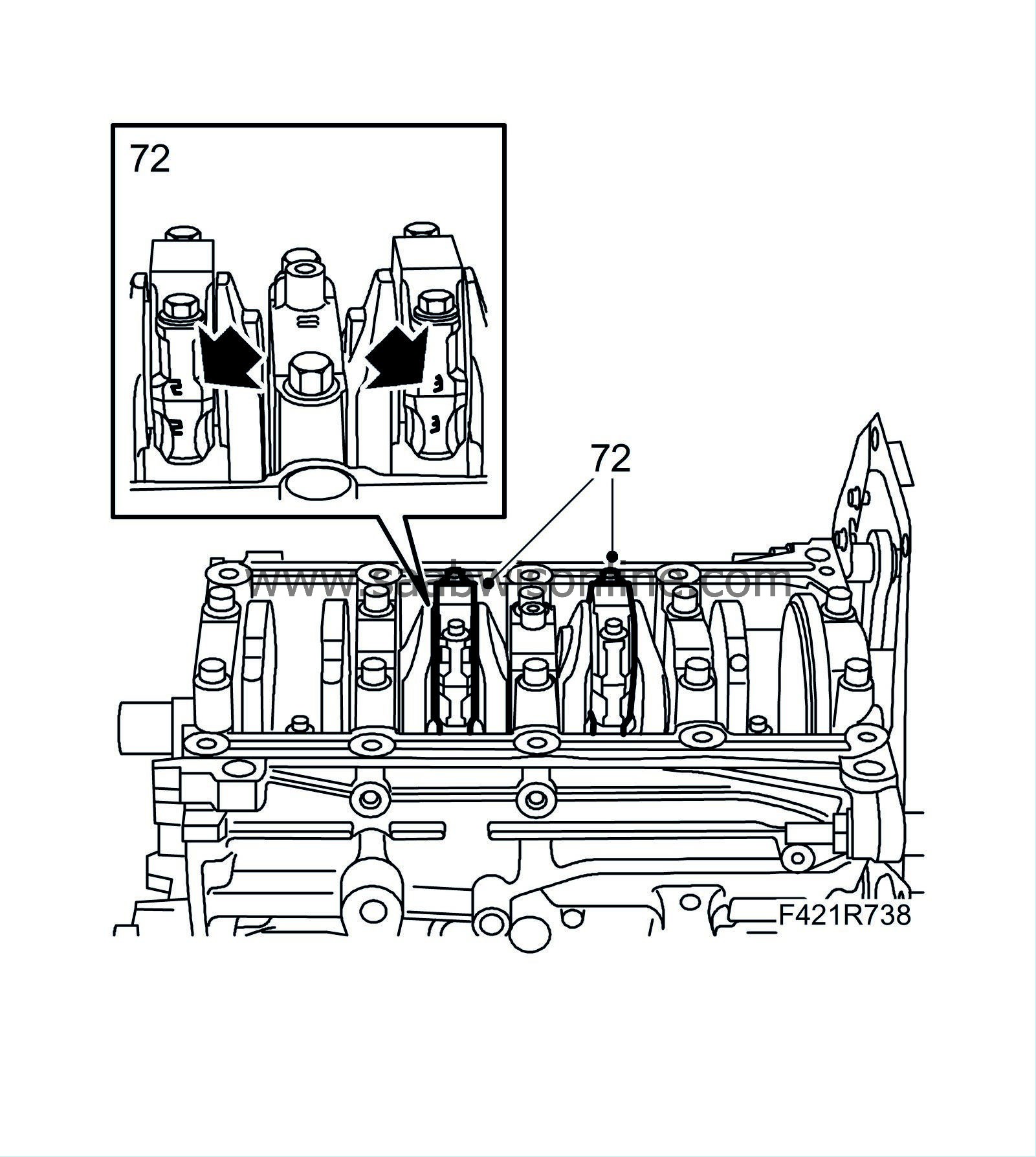
|
|
| 73. |
Turn the crankshaft 1/2 turn. Note the marking on the connecting rods and bearing caps so that the can be refitted in their original spots. Remove the connecting rod bearing caps. Remove the pistons and connecting rods from the cylinder bore of cylinders 1 and 4.
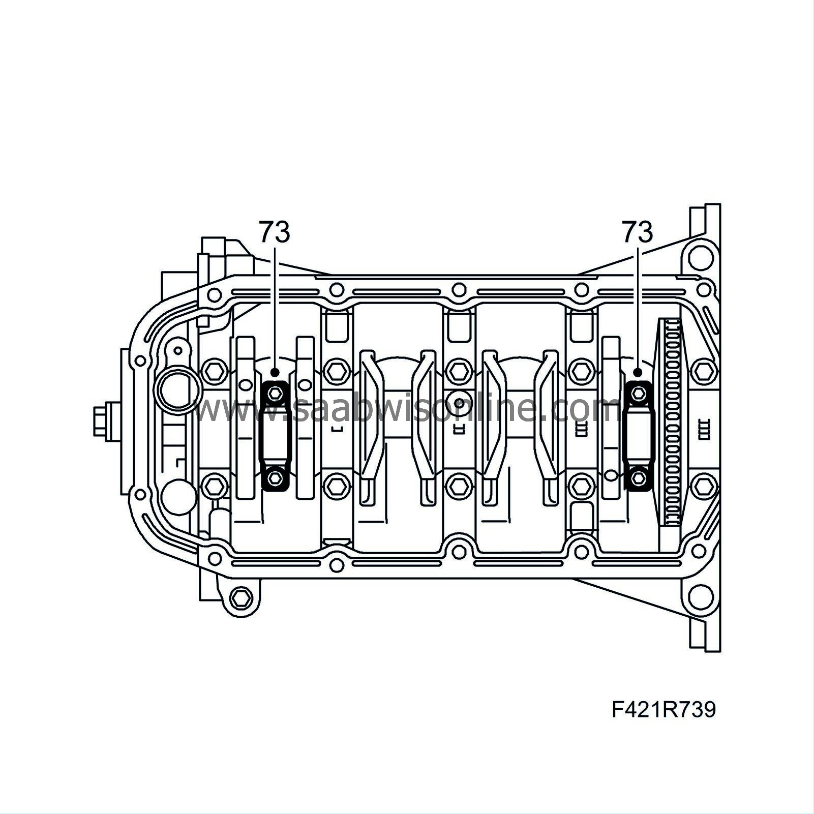
|
|
| 74. |
Remove the bearing shell from the connecting rod and bearing cap. Do not mix up the bearing shells.
|
|
| 75. |
Check crankshaft axial play using
78 40 622 Dial indicator
and
87 90 727 Dial gauge bracket
.
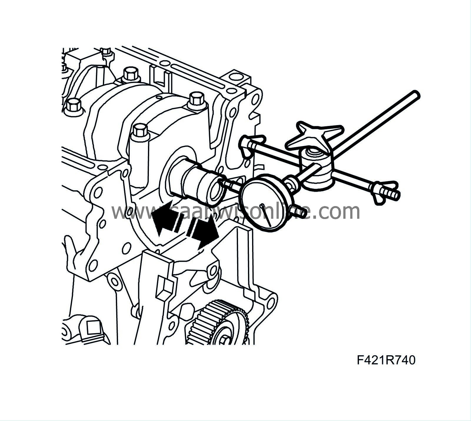
If bearing play is not within the interval specified above, use a suitable thrust bearing. |
||||
| 76. |
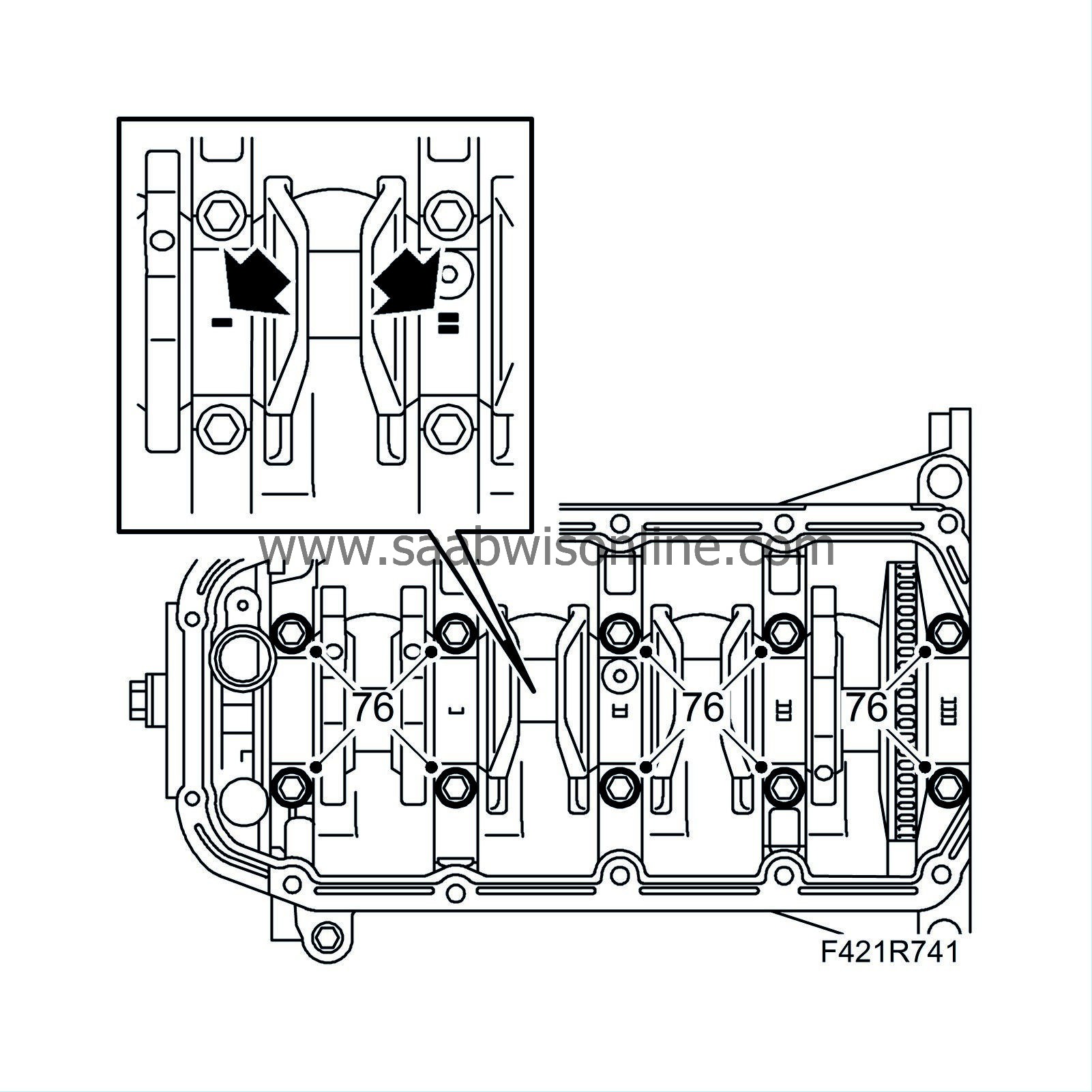
Remove the crankshaft bearing caps with lower bearing shells. Do not mix up the bearing shells.
|
|
| 77. |
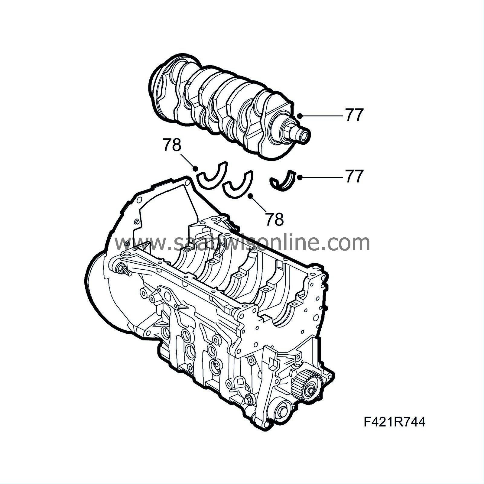
Lift out the crankshaft and the upper bearing caps. Do not mix up the bearing shells.
|
|
| 78. |
Lift out the thrust bearings.
|
|
| 79. |
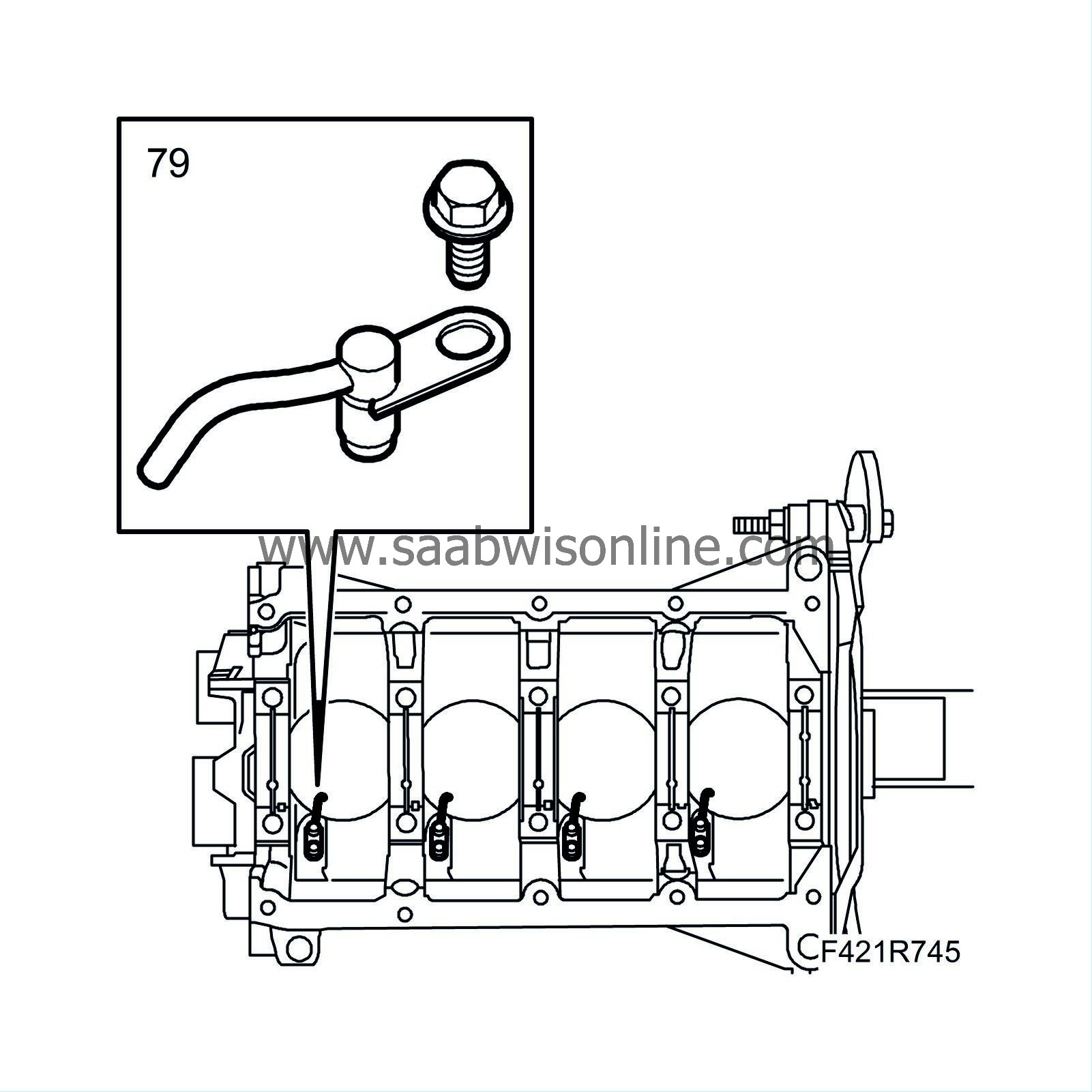
Remove the piston cooling nozzles.
|
|

