Cylinder head (in situ)
| Cylinder head (in situ) |
|
||||||||||||||||||||||
| To remove |
|
|||||||
| Important | ||
|
Always use wing covers when working in the engine bay. |
||
| 1. |
Remove
Timing belt (in situ)
.
|
|
| 3. |
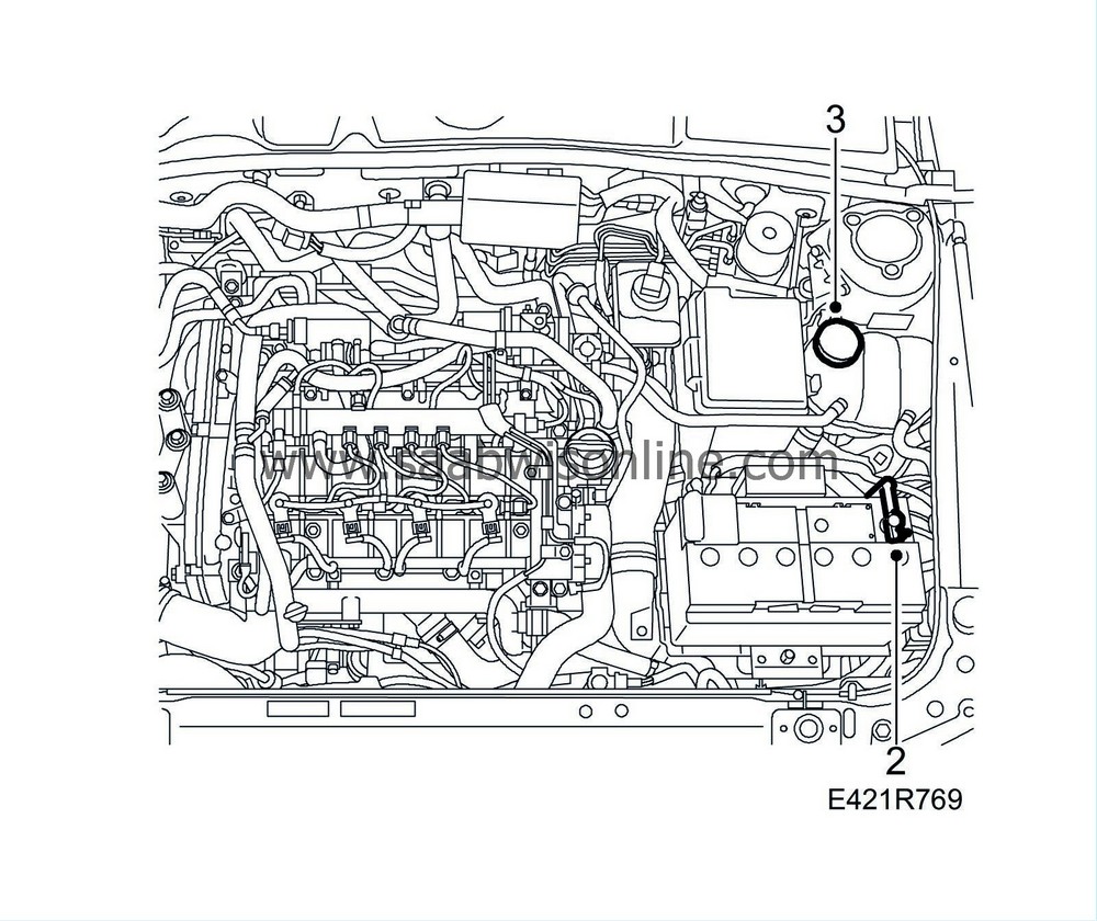
Loosen the coolant expansion tank cap to release any pressure.
|
|
| 4. |
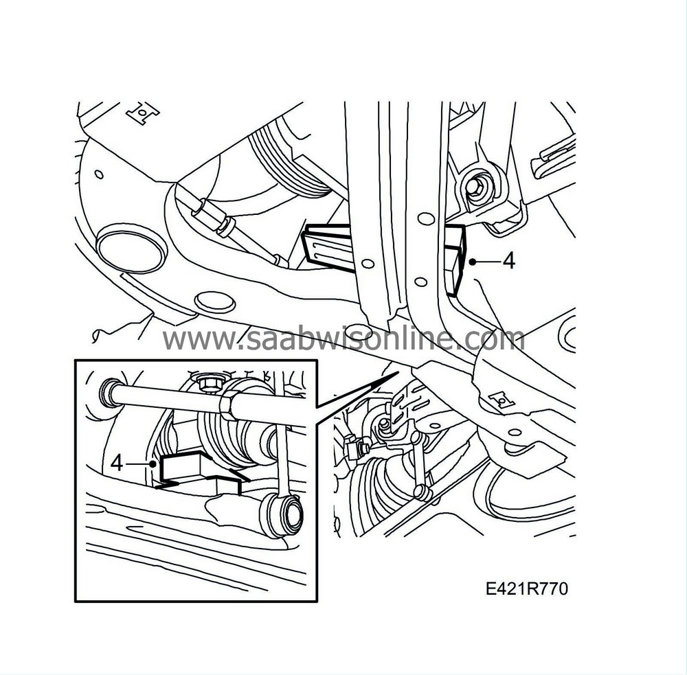
Raise the car and position plastic wedges or the like between the drive shaft and subframe as well as between the A/C compressor bracket and subframe.
|
|
| 5. |
Place a suitable receptacle under the radiator, attach a hose to the radiator and drain the coolant. Close the cock and fit the cover.
|
|
| 6. |
Remove the front exhaust pipe.

|
|
| 7. |
Detach the turbocharger oil return pipe from the engine block.
|
|
| 8. |
Remove the lower nuts and bolts from the turbocharger heat shield.

|
|
| 9. |
Slightly loosen the lower mounting of the front catalytic converter.
|
|
| 10. |
Lower the car and remove the lifting beam.
|
|
| 11. |
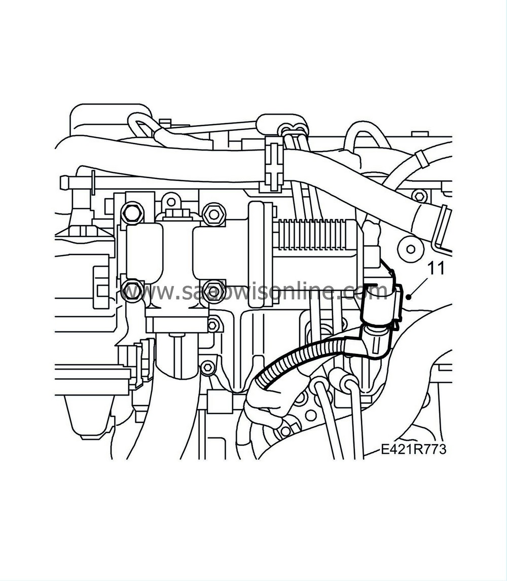
Detach the EGR valve connector.
|
|
| 12. |
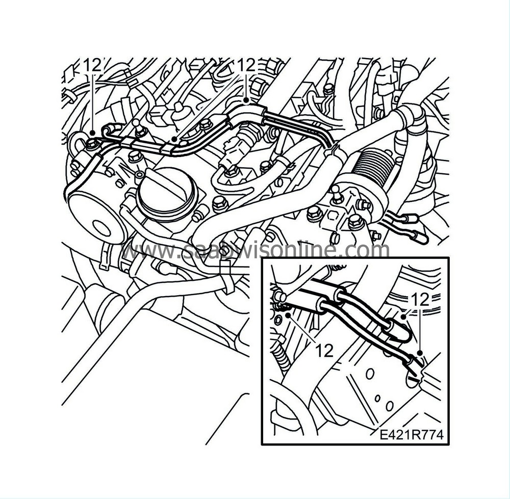
Detach the vacuum pipes from the camshaft housing and vacuum tank.
|
|
| 13. |
Remove the nuts from the radiator pipe holder on the starter motor bracket.

|
|
| 14. |
Detach the turbocharger delivery hose from the pipe and throttle body.
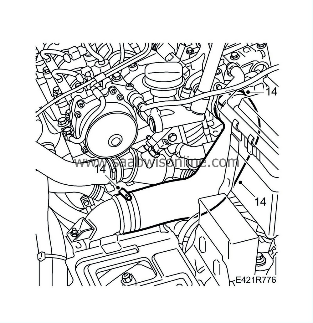
|
|
| 15. |
Remove the turbocharger intake manifold. Plug the connections.
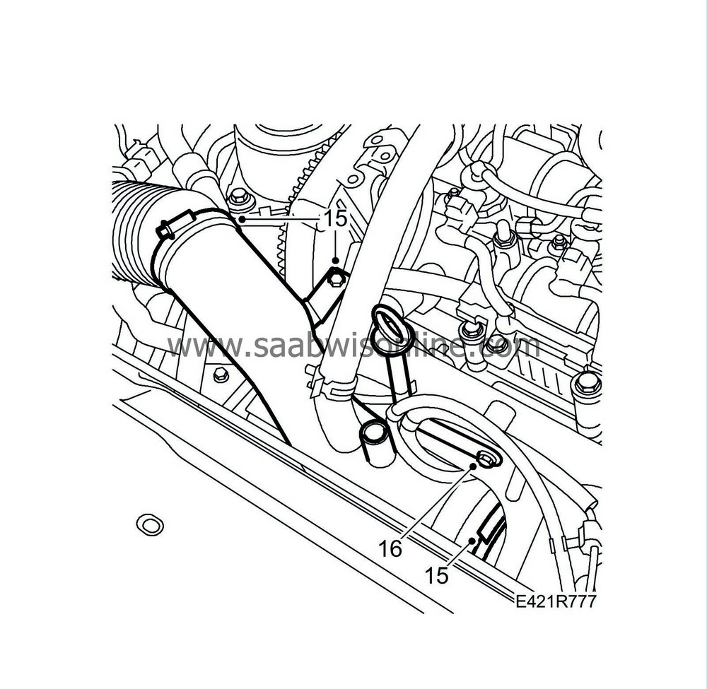
|
|
| 16. |
Remove the bolt securing the dipstick guide tube.
|
|
| 17. |
Remove the brake vacuum hose.

|
|
| 18. |
Unplug the connector of the coolant temp. sensor.
|
|
| 19. |
Detach the expansion tank bleeder hose.
|
|
| 20. |
Remove the crankcase ventilation hose from the clip. Move the hose aside.
|
|
| 21. |
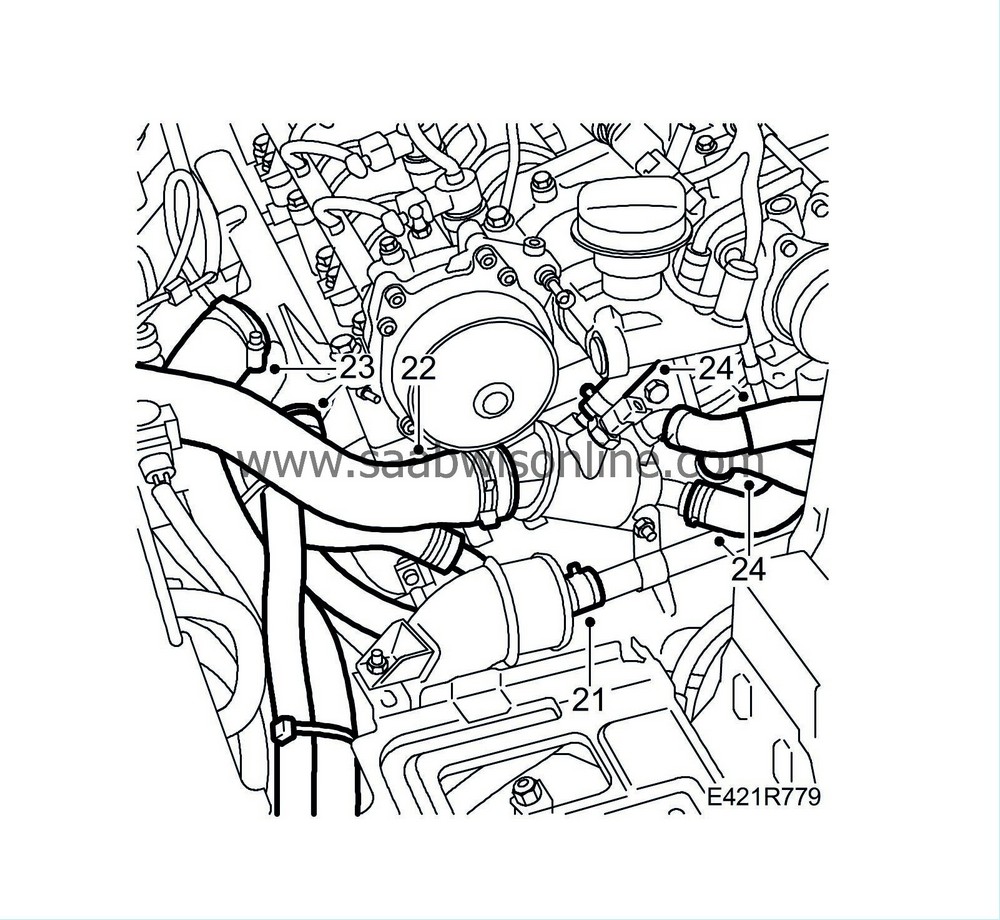
Detach the lower radiator hose from the coolant pipe.
|
|
| 22. |
Detach the upper radiator hose from the thermostat housing.
|
|
| 23. |
Detach the coolant hoses from the coolant pipe.
|
|
| 24. |
Detach the hoses from the thermostat housing.
|
|
| 25. |
Slightly slacken the bolt securing the turbo inlet pipe's upper retaining bracket.

|
|
| 26. |
Detach the EGR pipe between the exhaust manifold and heat exchanger.
|
|
| 27. |
Remove the heat shield.
|
|
| 28. |
Remove the exhaust manifold nuts and move it forward so that the studs are accessible.

|
|
| 29. |
Detach the return fuel pipe from the return fuel tank.

|
|
| 30. |
Detach the fuel hose from the high pressure pump.
|
|
| 31. |
Detach the wiring harness from the crankcase ventilation pipe. Remove the bolts holding the pipe in place and move it aside.
Cars with preheated crankcase ventilation:
Cut the cable tie and remove the brackets.
|
|
| 32. |
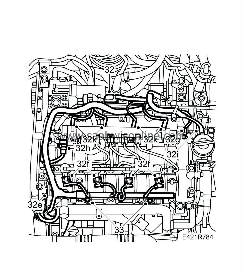
Unplug the following connectors:
|
|
| 32.a. |
Mass air flow sensor connector. (686)
|
| 32.b. |
Wiring harness connector. Fit bracket and cable tie.

|
| 32.c. |
A/C compressor connector (170).
|
| 32.d. |
Front temperature sensor (602).
|
| 32.e. |
Camshaft position sensor (555).
|
| 32.f. |
Injectors (206).
|
| 32.g. |
Fuel pressure sensor (653).
|
| 32.h. |
Fuel pressure solenoid valve (652a).
|
| 32.i. |
Electronic throttle actuator (604).
|
| 32.j. |
Intake air sensor (688).
|
| 32.k. |
Glow plug connector (398).
|
| 33. |
Remove the retaining bolts of the cable duct and move the wiring harness aside.
|
|
| 34. |
Remove the vacuum reservoir.

|
|
| 35. |
Remove the nuts and bolts holding the oil trap bracket in place and move it aside.
|
|
| 36. |
Remove the combustion circulation actuator. Carefully bend the control arm from the ball coupling.

|
|
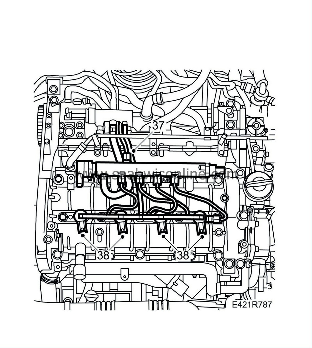
| 37. |
Detach the fuel delivery pipe between the pump and fuel rail.
|
||||||||||
| 38. |
Remove the injector (206)
|
|
| 39. |
Remove the fuel rail and hose.

|
|
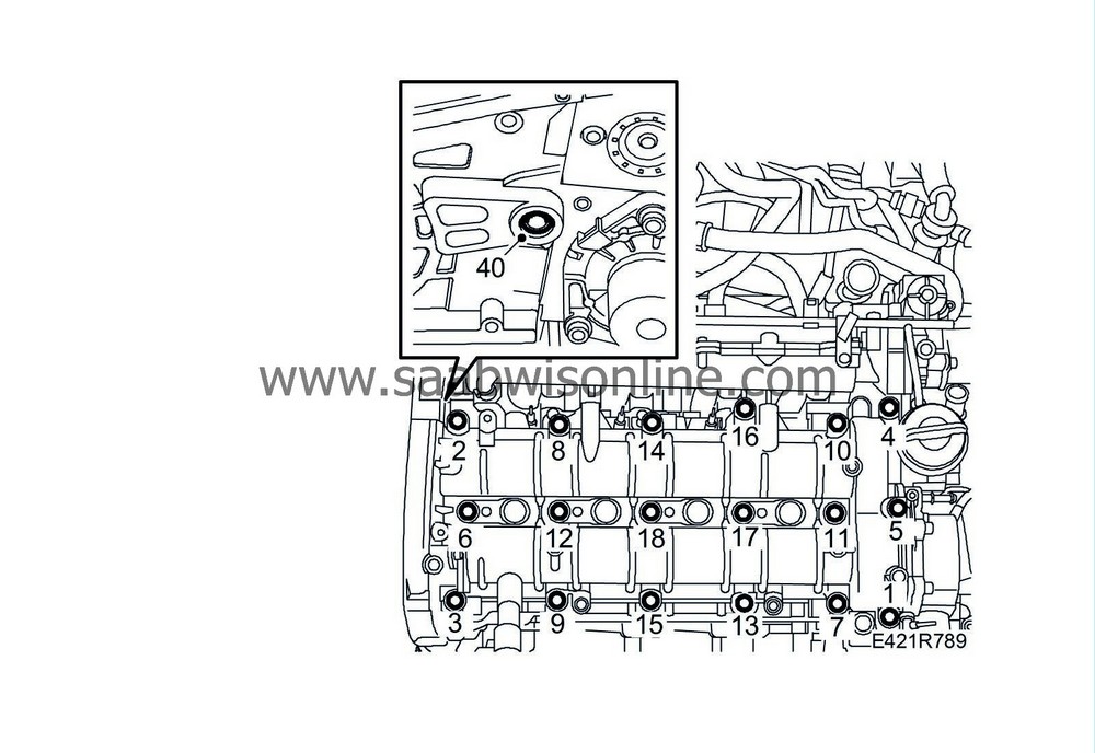
| 40. |
Remove the bolt between the fuel pump bracket and cylinder head. Slacken the spacer bolt a few turns.
|
|
| 41. |
Loosen and remove the camshaft shaft housing and the guide sleeves. Remove in alternating order as illustrated.
|
|
| 42. |
Remove the cylinder head by undoing the bolts in the order illustrated.

|
|
| 43. |
Carefully lift off the cylinder head.
|
||||||||||
| 44. |
Remove the engine block guide sleeves.
|
|
| To fit |
| 1. |
Clean the bolt holes in the cylinder block.
|
|
| 2. |
Clean away any gasket residue from the sealing surfaces of the cylinder head and cylinder block.
|
|
| 3. |
Use a steel rule to check that the cylinder head and cylinder block are flat and the sealing surfaces are not damaged.
|
||||||||||
| 4. |
Position the guide sleeves on the cylinder block.

|
|
| 5. |
Position a new gasket with the same thickness as the old one.
|
|
| 6. |
Fit the cylinder head to the cylinder block.
|
|
| 7. |
Tighten the cylinder head bolts in the order illustrated.
Tightening torques Step I: 65 Nm (48 lbf ft) Step II: +90° Step III: +90° Step IV: +90° 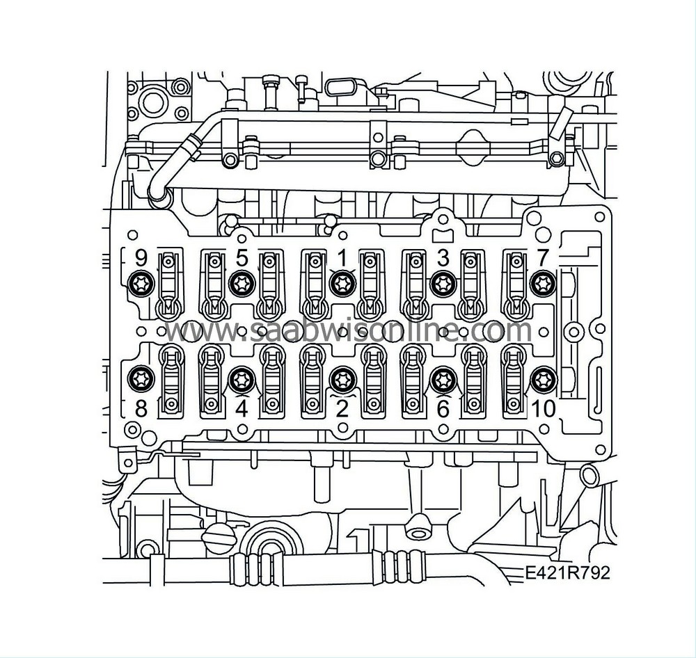
|
|
| 8. |
Clean away any gasket residue from the sealing surfaces of the cylinder head and camshaft housing.
|
|
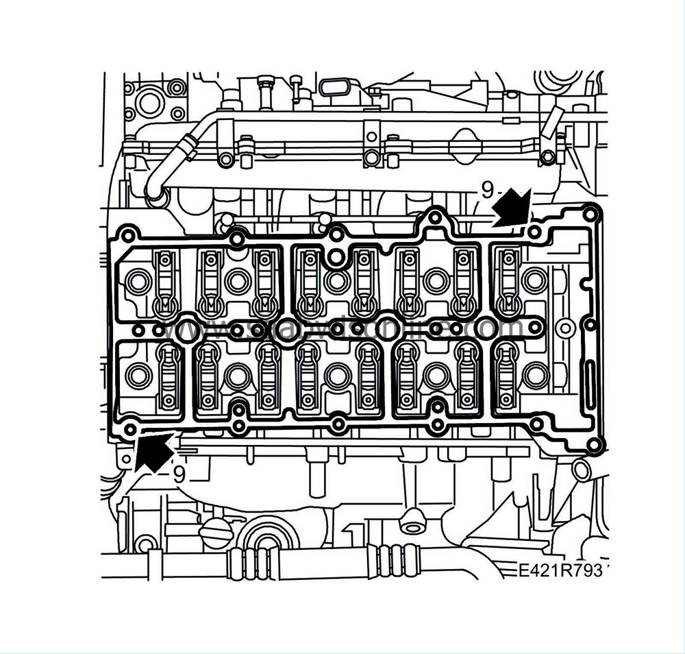
| 9. |
Fit the guide sleeves and position a new gasket on the cylinder head.

|
|||||||
| 10. |
Fit the camshaft housing, tightening the bolts alternatingly. Check that the guide sleeves are properly positioned in the camshaft housing.
Tightening torque: 25 Nm (18 lbf ft) |
|
| 11. |
Screw in the spacer sleeve to the cylinder head and fit the bolt.

|
|
| 12. |
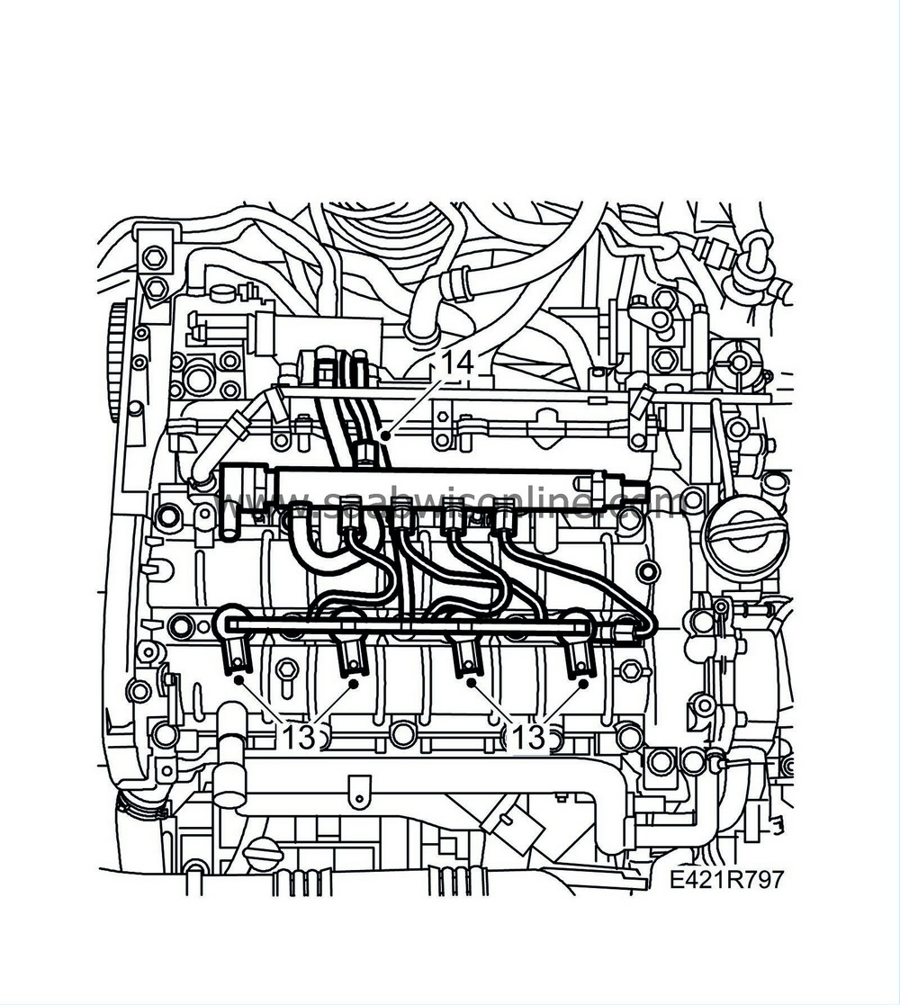
Fit the fuel rail and hose.

|
|
| 13. |
Fit the injector (206)
|
|
| 14. |
Fit the fuel delivery pipe between the pump and fuel rail.
Tightening torque: 25 Nm (18 lbf ft) |
|
| 15. |
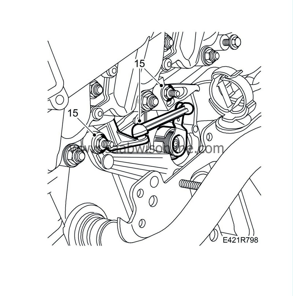
Fit the combustion circulation actuator and attach the control arm to the ball coupling.
|
|
| 16. |
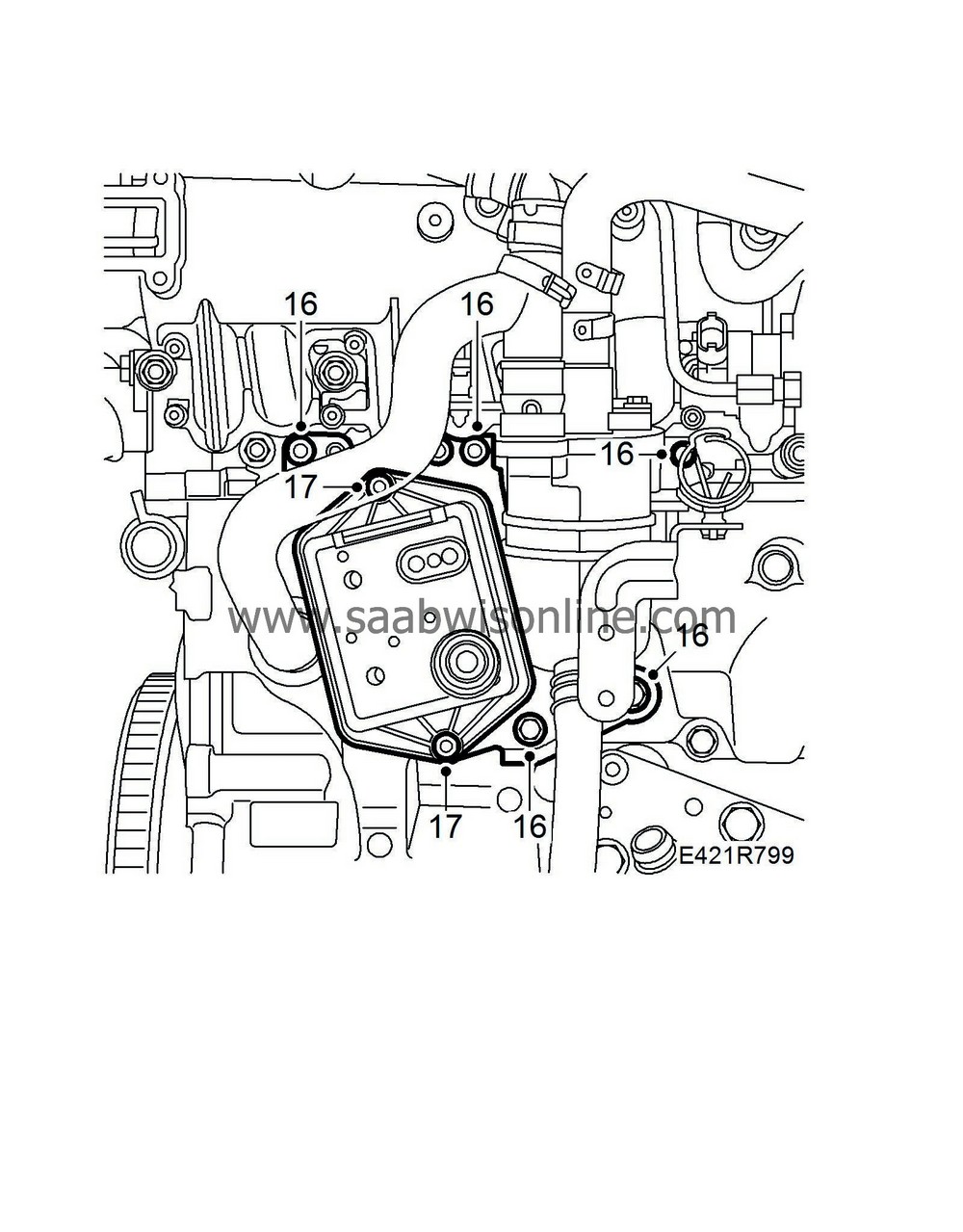
Fit the nuts and bolts holding the oil trap bracket in place.
|
|
| 17. |
Fit the vacuum reservoir.
|
|
| 18. |
Fit the wiring harness and cable duct retaining bolts.
|
|
| 19. |
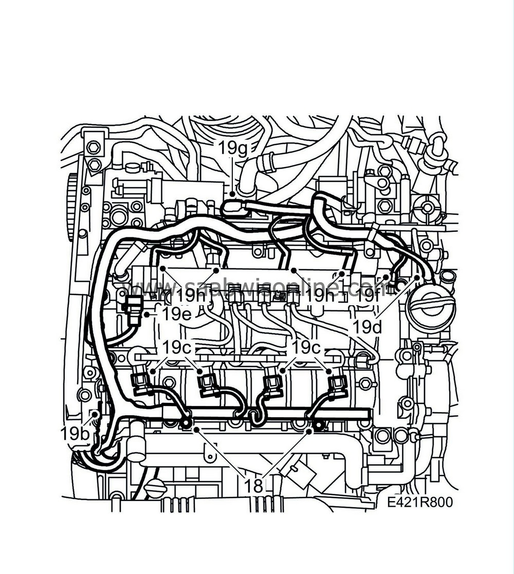
Reposition the engine harness and plug in the following connectors:
|
|
| 19.a. |
Front temperature sensor (602).
|
| 19.b. |
Camshaft position sensor (555)
|
| 19.c. |
Injectors (206).
|
| 19.d. |
Fuel pressure sensor (653).
|
| 19.e. |
Fuel pressure solenoid valve (652a).
|
| 19.f. |
Throttle body actuator (604)
|
| 19.g. |
Sensor, intake air (688)
|
| 19.h. |
Glow plug connector (398).
|
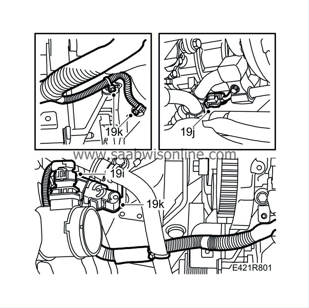
| 19.i. |
Mass air flow sensor connector. (686)
|
| 19.j. |
A/C compressor connector (170).
|
| 19.k. |
Wiring harness connector. Fit bracket and cable tie.
|
| 20. |
Cars with preheated crankcase ventilation:
Fit the brackets.
All:
Fit the bolts of the crankcase ventilation pipe. Fit the wiring harness.

|
|
| 21. |
Attach the fuel hose to the high pressure pump.
|
|
| 22. |
Attach the return fuel pipe to the return fuel tank.
|
|
| 23. |
Fit the exhaust manifold nuts and move it forward so that the studs are accessible. Use a new gasket.
Tightening torque: 20 Nm (15 lbf ft) 
|
|
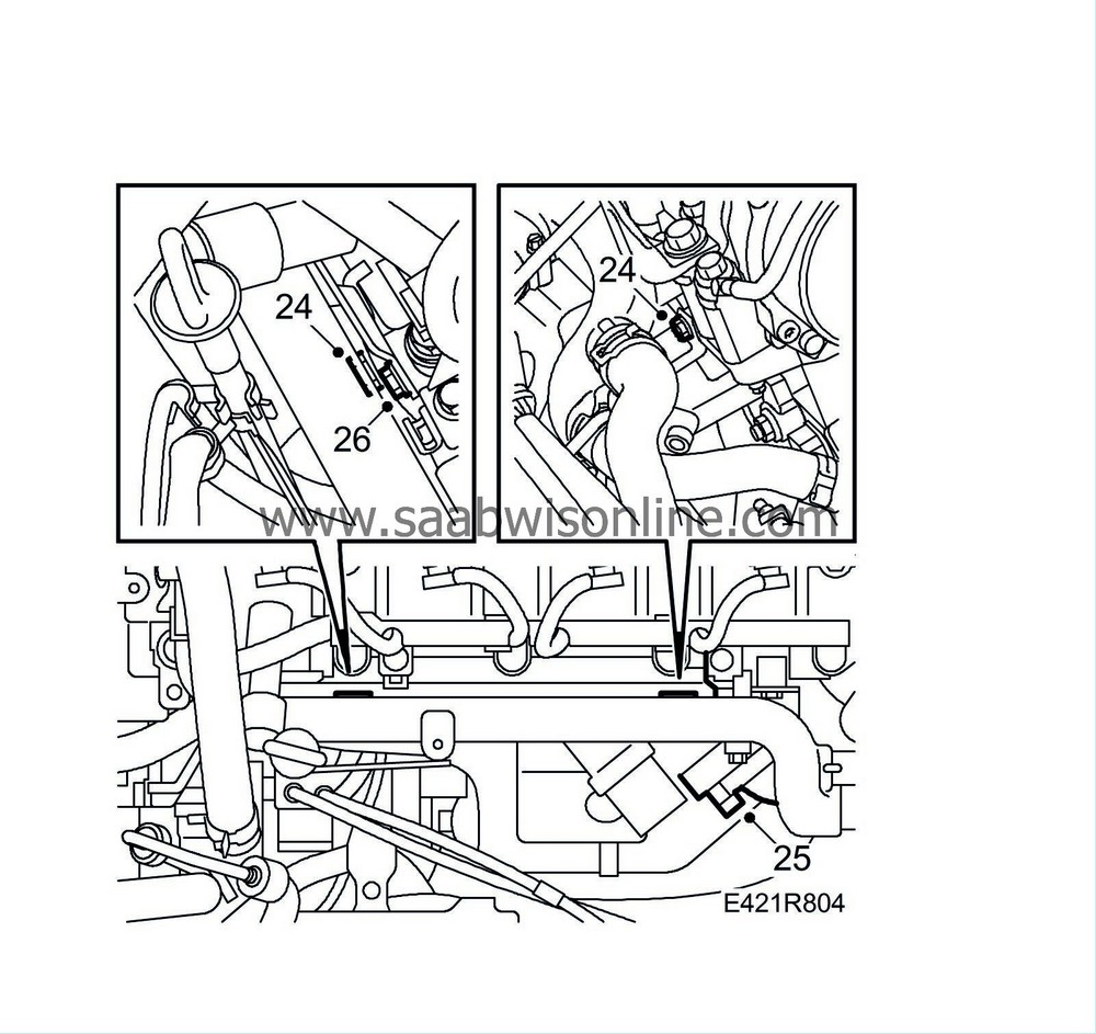
| 24. |
Fit the upper bolts of the heat shield.
|
|
| 25. |
Attach the EGR pipe between the exhaust manifold and the heat exchanger. Use new gaskets.
|
|
| 26. |
Tighten the bolt securing the turbo inlet pipe's upper retaining bracket.
|
|
| 27. |
Attach the hoses to the thermostat housing.

|
|
| 28. |
Attach the coolant hoses to the coolant pipe.
|
|
| 29. |
Attach the upper radiator hose to the thermostat housing.
|
|
| 30. |
Attach the lower radiator hose to the coolant pipe.
|
|
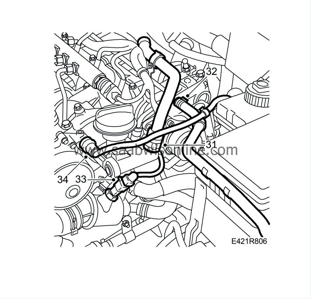
| 31. |
Fit the crankcase ventilation hose to the clip.
|
|
| 32. |
Fit the expansion tank bleeder hose.
|
|
| 33. |
Plug in the connector of the coolant temp. sensor.
|
|
| 34. |
Attach the brake vacuum hose.
|
|
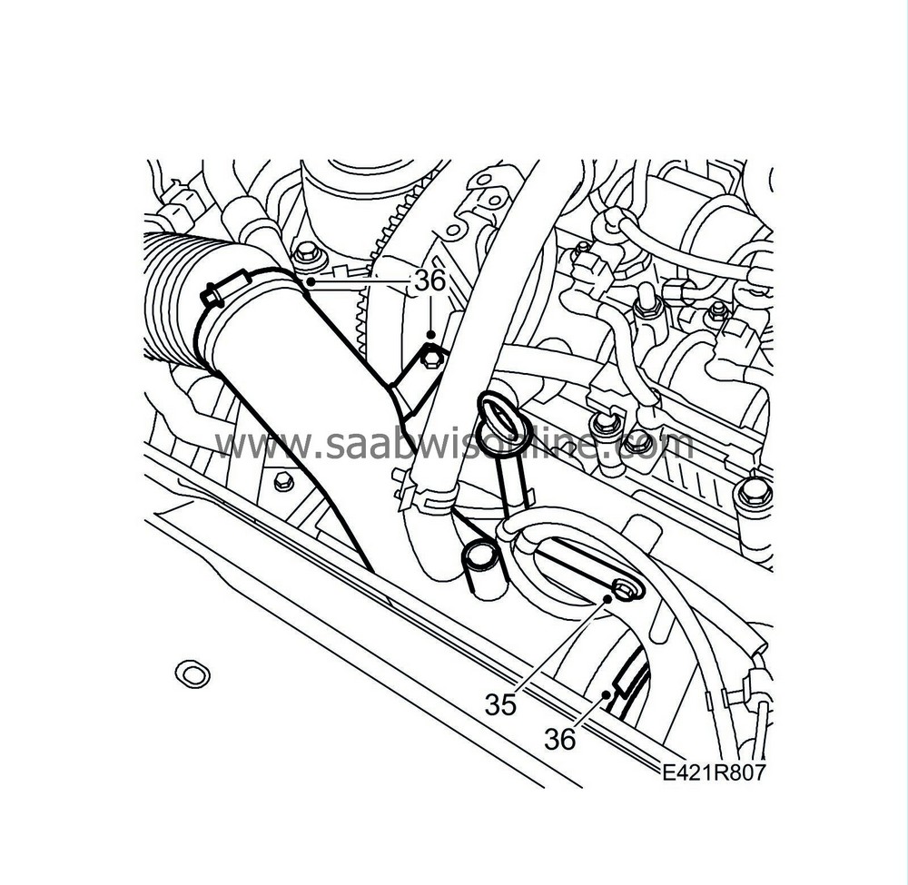
| 35. |
Fit the bolt securing the dipstick guide tube.
|
|
| 36. |
Remove the plugs and attach the turbocharger intake manifold.
|
|
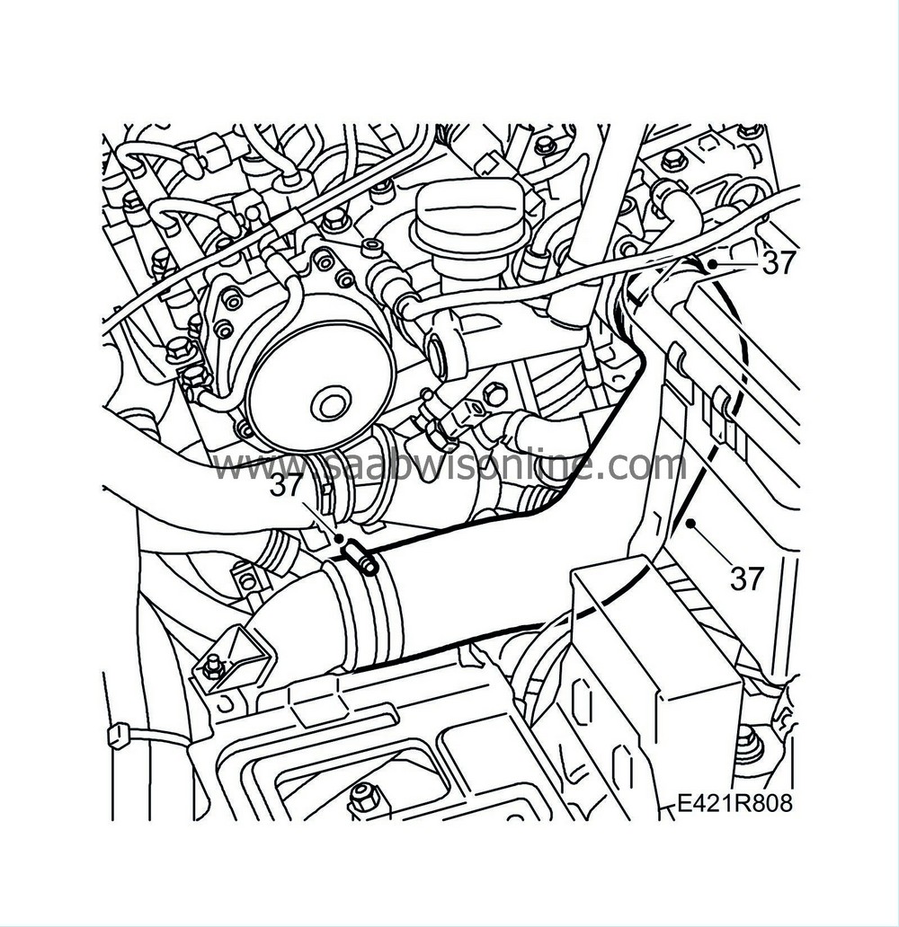
| 37. |
Attach the turbocharger delivery hose to the pipe and throttle body.
|
|
| 38. |
Fit the nuts from the radiator pipe holder on the starter motor bracket.
Tightening torque: 10 Nm (7 lbf ft) 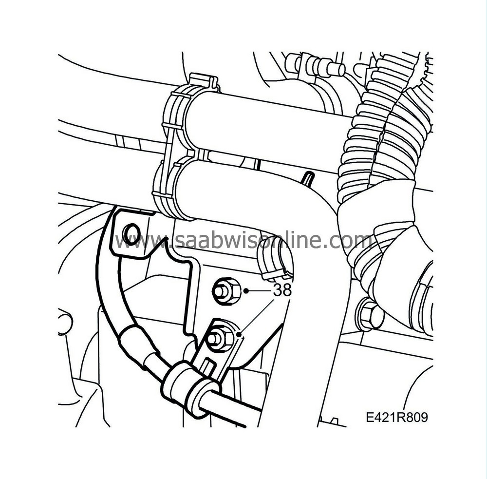
|
|
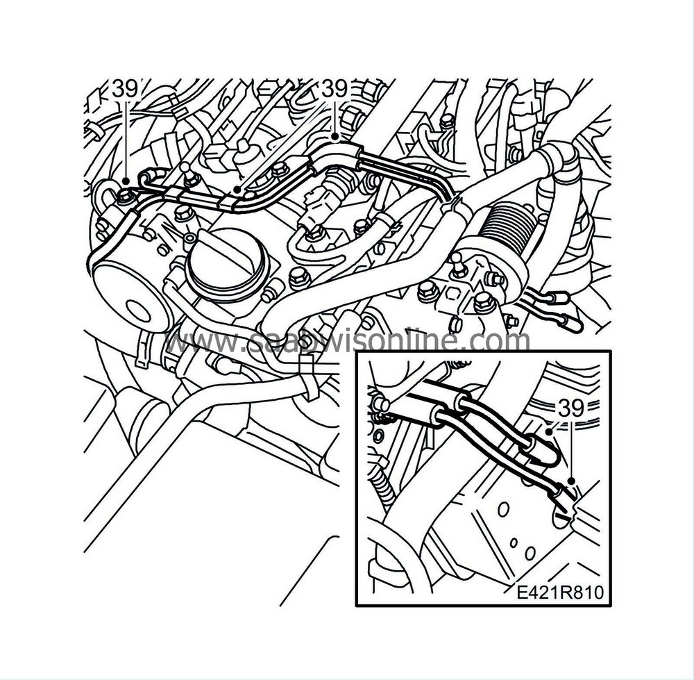
| 39. |
Attach the vacuum pipes to the camshaft housing and vacuum tank.
|
|
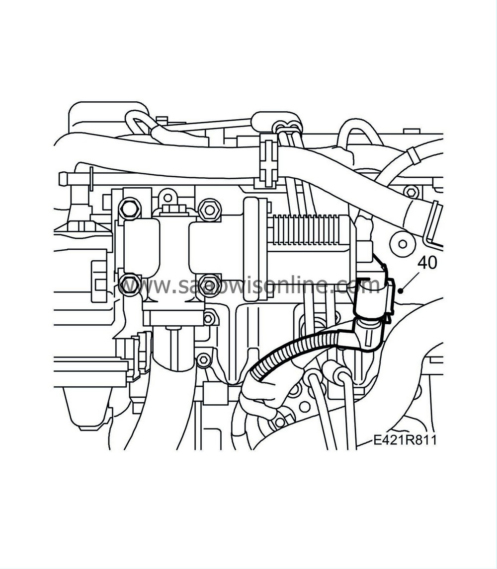
| 40. |
Attach the EGR valve connector.
|
|
| 41. |
Raise the car.
|
|
| 42. |
Tighten the lower mounting of the front catalytic converter.
Tightening torque: 25 Nm (18 lbf ft) 
|
|
| 43. |
Fit the lower nuts and bolts of the turbocharger heat shield.
|
|
| 44. |
Attach the turbocharger oil return pipe to the cylinder block.
Tightening torque: 20 Nm (15 lbf ft) |
|
| 45. |
Attach the front exhaust pipe using new gaskets.
Tightening torque: 25 Nm (18 lbf ft) 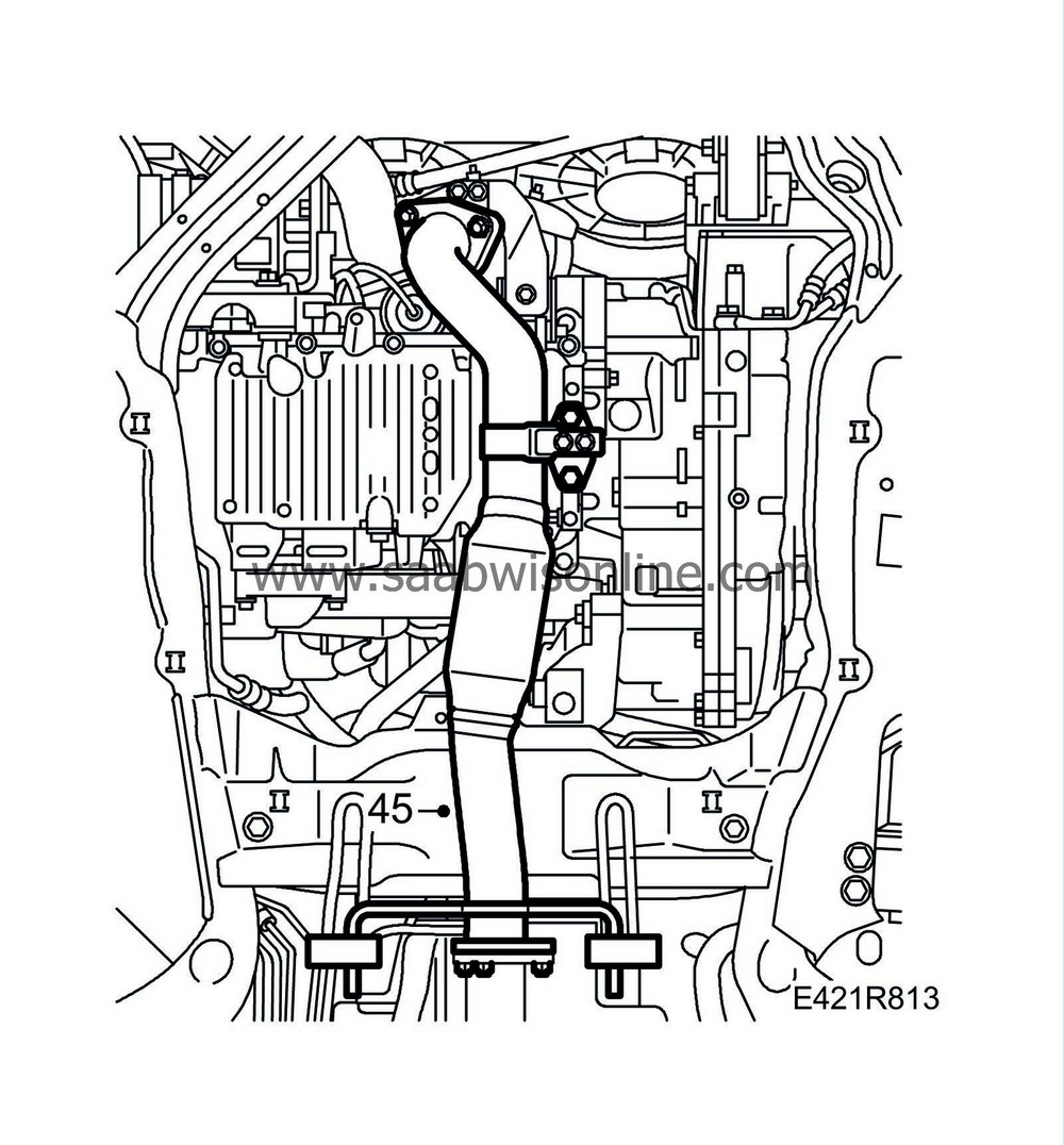
|
|
| 46. |
Connect the negative battery cable.
|
|
| 47. |
Fit
Timing belt (in situ)
.
|
|
| 48. |
Pressure test - see Cooling system, pressure testing - and fill coolant - see Filling and bleeding cooling system.
|
|
| 49. |
Carry out
Procedure after battery disconnection
.
|
|
| 50. |
Check and clear any diagnostic trouble codes using the diagnostic tool.
|
|

 Warning
