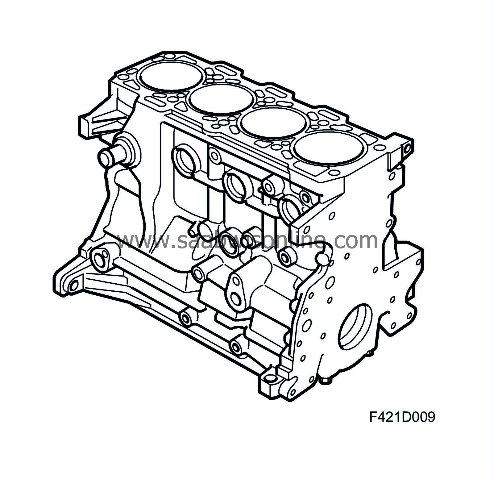
Detailed description
| Detailed description |
| Pistons |
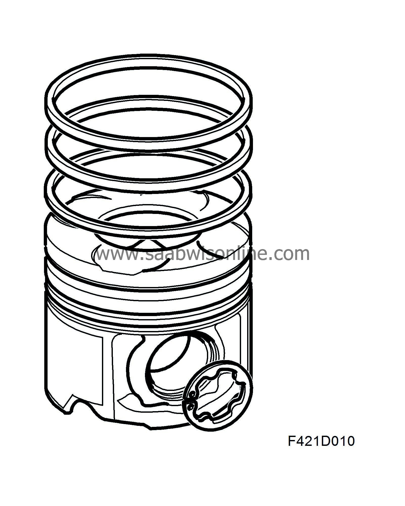
The light alloy pistons are equipped with grooves for two compression rings and one oil scraper ring. The upper compression ring is flat and has a chrome or molybdenum coating. The lower compression ring has oil scraper properties and is somewhat wider than the upper one. The oil scraper ring has three sections. The piston has drilled holes to allow oil from the oil scraper ring groove to drain to the inside of the piston and drip down into the crankcase. The upper piston ring groove has a steel inlay.
The piston crown contains a cavity which together with the flat surface of the cylinder head constitutes the combustion chamber. Because of its shape, the air reaches a very high speed in the combustion chamber just before the piston reaches its upper position. This is important to ensure that the fuel and air are mixed homogeneously. The result is an engine with high performance but low emissions.
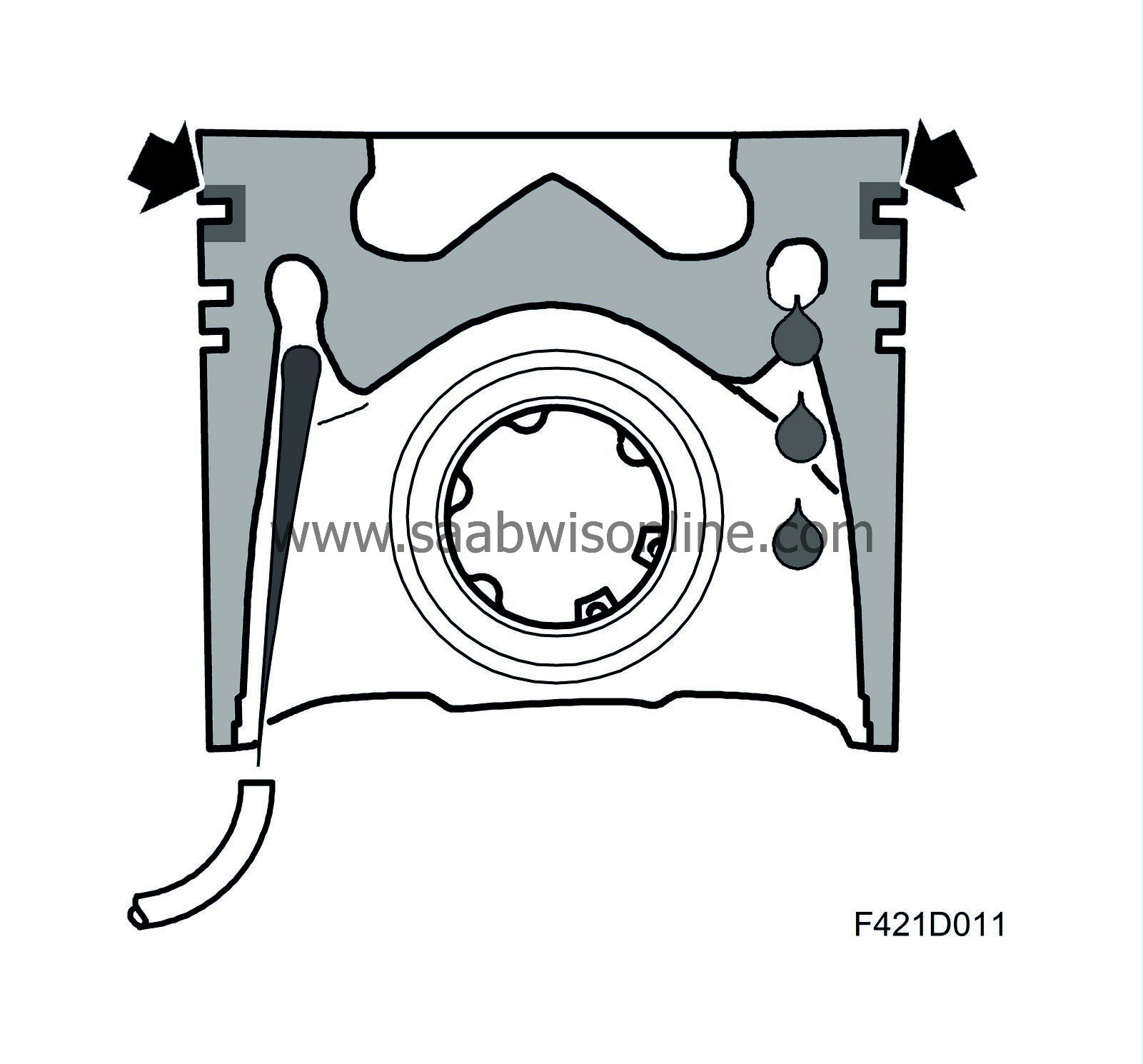
Z19DTH: The pistons have cooling ducts of effective cooling. A cooling coil is located inside the piston at the same height as the second piston ring. The cylinder block contains nozzles (one for each cylinder). The oil jet from the nozzle hits a hole that leads into the cooling coil. At the other side of the cooling coil there is an outlet hole for the cooling oil, which drops down into the crankcase. This makes high power extraction possible without overheating of the pistons.
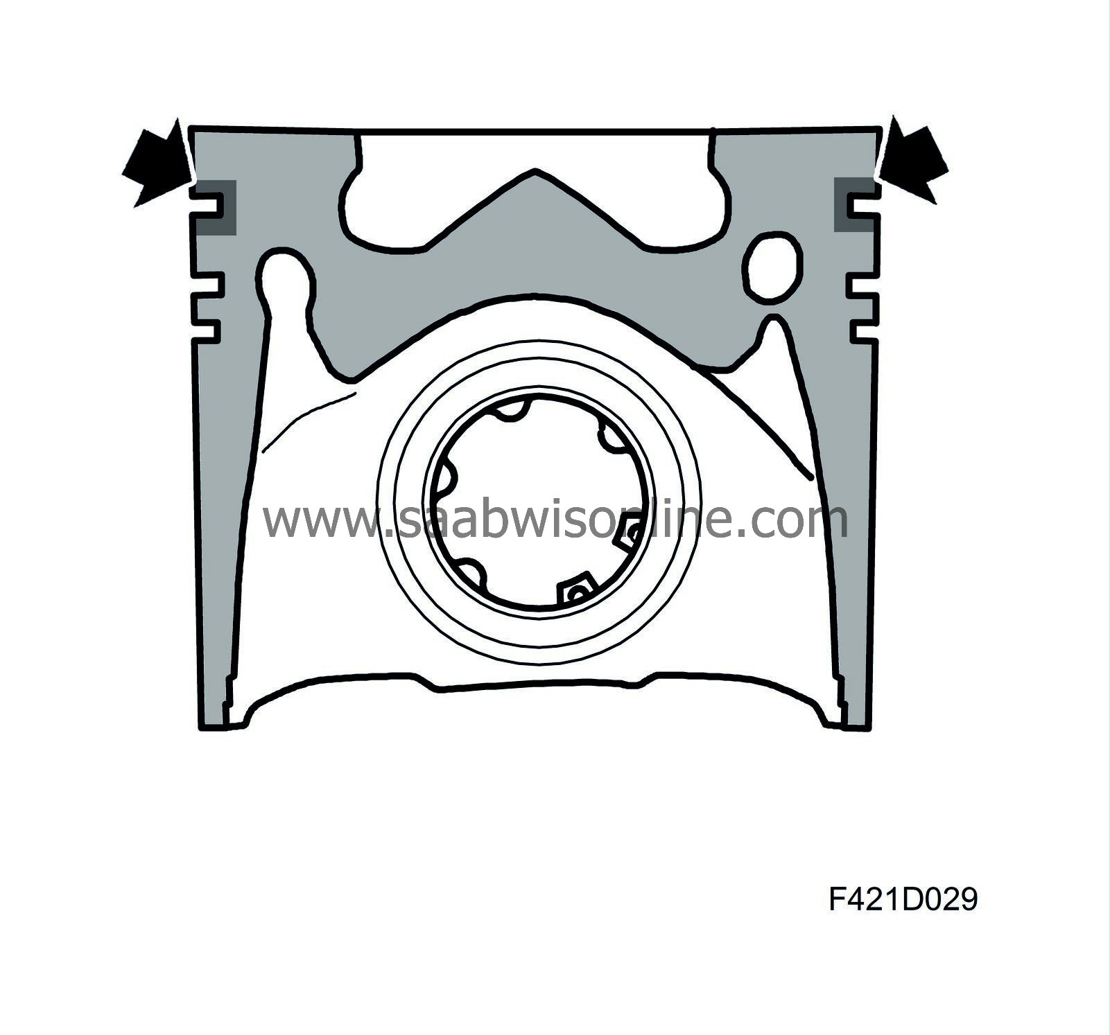
The pistons are surface-treated to reduce friction (and thereby wear) against the cylinder walls. The piston skirts are coated with graphite.
The hole for the fully floating gudgeon pin has bearing bushings for increased strength. The gudgeon pin is slightly off-centre.
The compression ratio is 17.5:1.
| Connecting rods |
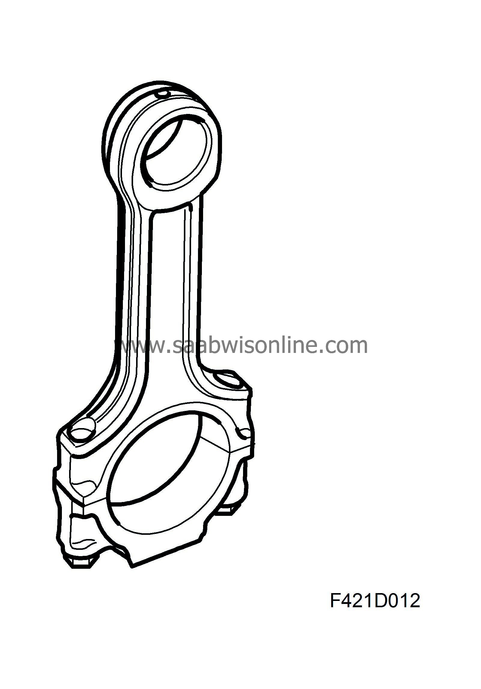
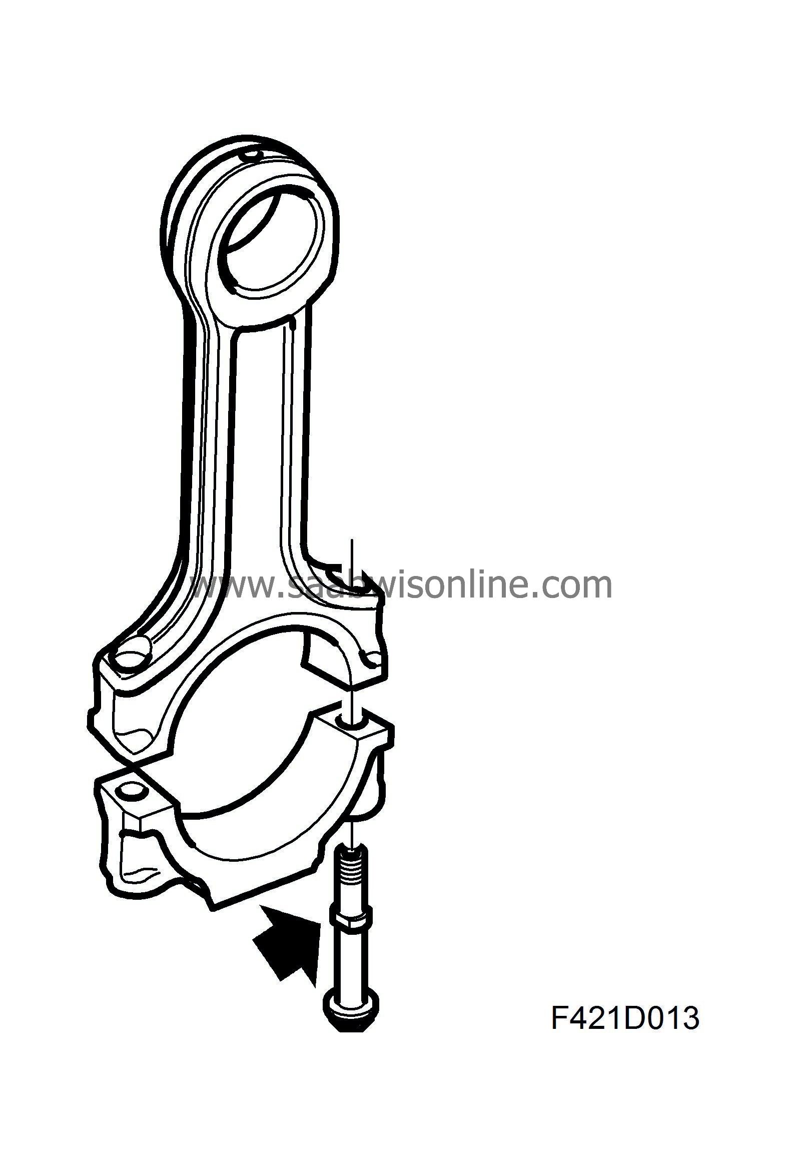
The connecting rods in Z19DTH are forged. They have a bushing for the gudgeon pin bearing. The gudgeon pin bushing and connecting rod bearing caps can be replaced. There is a drilled hole up at the small end for lubrication of the gudgeon pin bearing bushing.
The gudgeon pin floats in the piston and connecting rod. The pin's axial movement is limited by circlips in the piston's gudgeon pin hole.
The bearing cap of the connecting rod's big end has ground surfaces facing the connecting rod. The bolts have a collar to guide the bearing cap toward the connecting rod.
The engines have robust connecting rods.
| Crankshaft assembly |
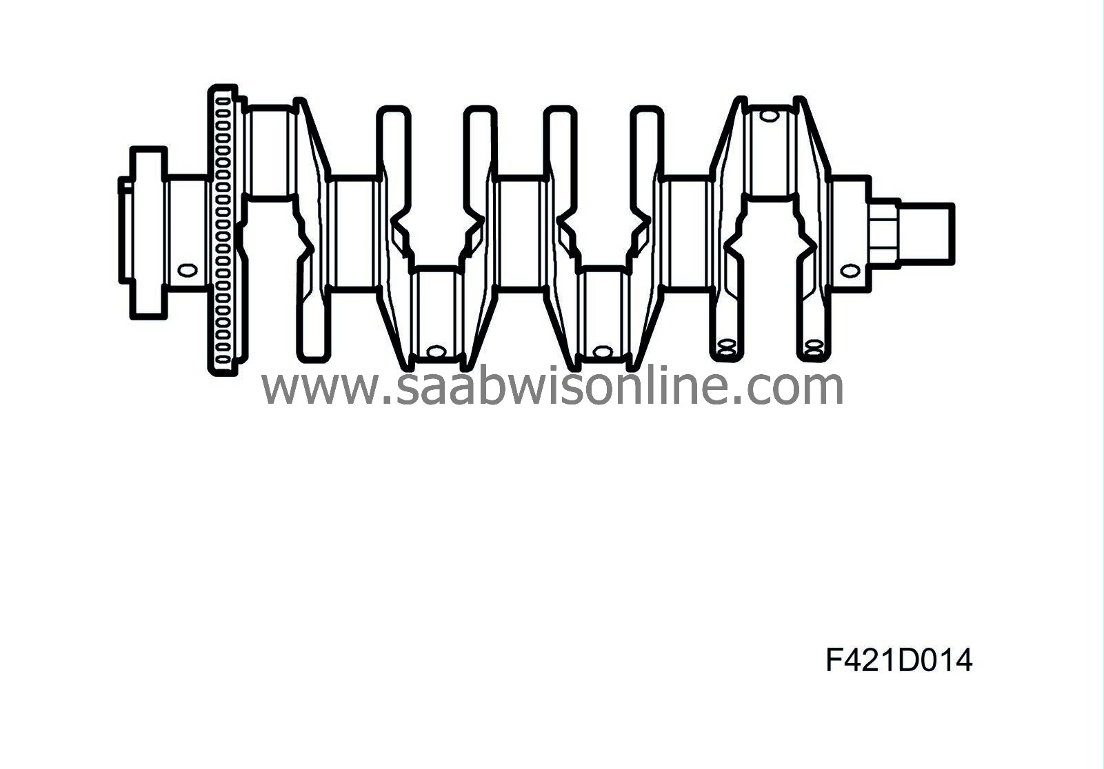
The crankshaft is forged and has ground, surface hardened bearing journals. This generates a hard outer layer that protects against wear. The crankshaft is mounted in 5 main bearings, with the centre bearing also serving as an axial guide bearing. The shaft contains drilled ducts for lubrication oil. All main bearing shells are replaceable.
| Cylinder head |
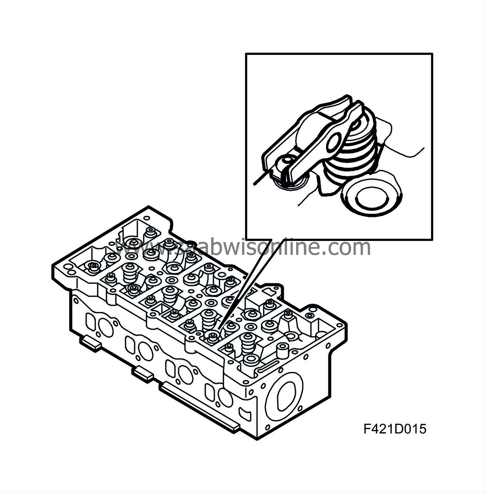
The cylinder head is precision cast in light metal alloy and is mounted on the cylinder block with a bolted joint. The cylinder head has 4 valves per cylinder so that they are filled efficiently. The injectors have a central location. The two exhaust ducts are identical while the intake ducts have different shapes. One duct is used for light engine loads. When the load is high, the other duct opens via a flap regulated by ECM. This improves swirl formation. The cylinder head is sealed with a meal gasket consisting of three bearings. The gasket is available in three thicknesses.
| Camshaft housing |

The camshafts share a common housing, which also serves as the cylinder head cover. The camshaft housing has two bearing races, each containing five bearings. The camshafts are mounted on bearings directly in the camshaft metal. The gearings are pressure lubricated.
| Intake manifold |
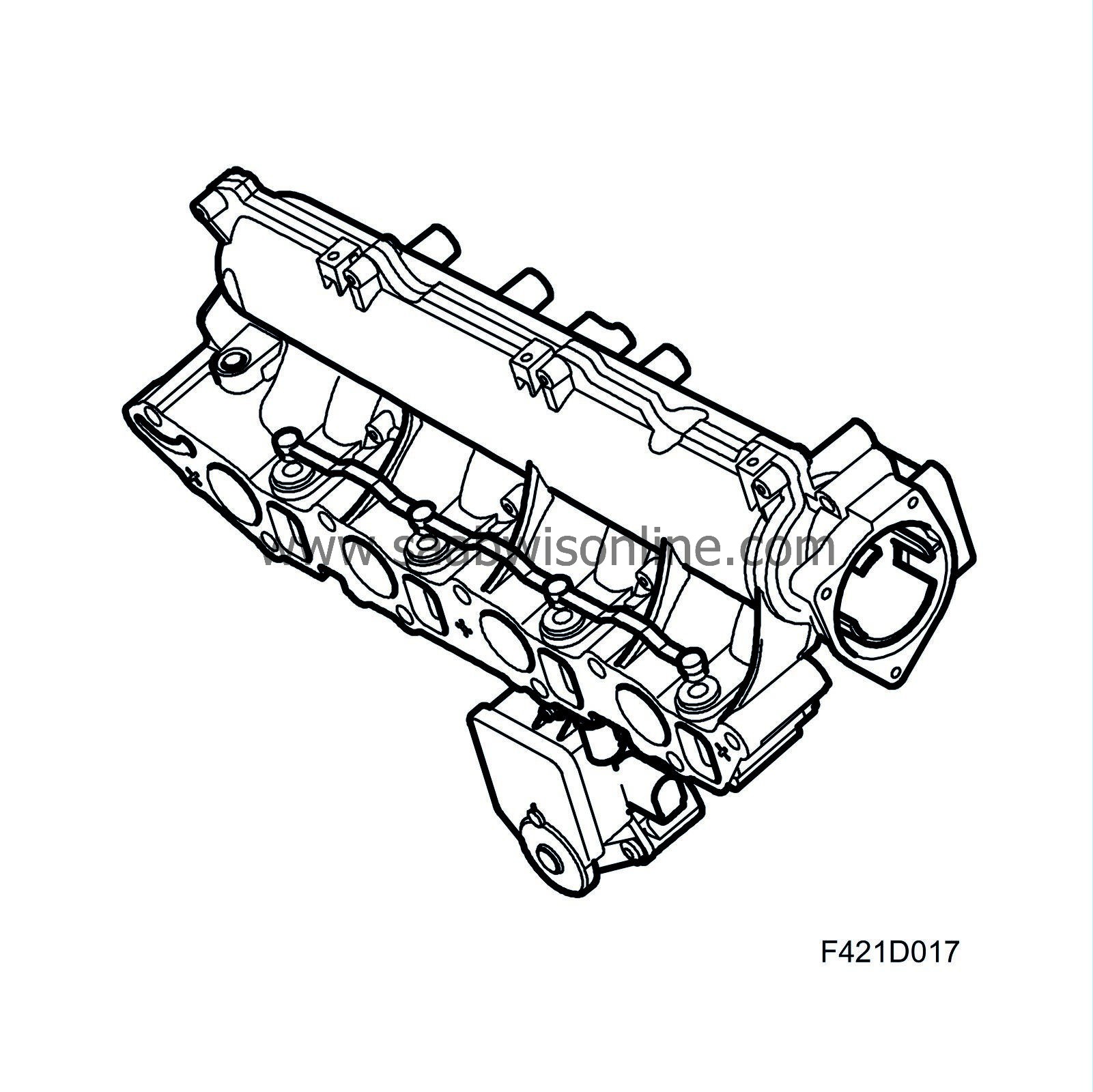
General
The intake manifold distributes the air to each cylinder. The throttle body, EGR valve, return fuel tank, swirl throttle and the actuating motor for the swirl throttle are housed on the intake manifold.The intake manifold consists of a plenum chamber and eight inlet ducts to the cylinder head - two for each cylinder. The inlet ducts are designed to guide the air from the plenum chamber into the cylinder head inlet ducts. The cylinder head ducts are designed to provide a good degree of fullness and good tumble and swirl formation. Strong swirl formation is especially desirable at low engine loads so that there is a good blend of air and injected fuel. One of the inlet ducts to each cylinder is designed to generate a good screwing movement to the air, which is then led into the cylinder. The other duct is designed to cause a wider but small screwing movement of the air, known as tumble. To generate this tumble and swirl during operation, the engine intake manifold is equipped with a throttle in each tumble duct. The throttle is operated by an actuating motor.
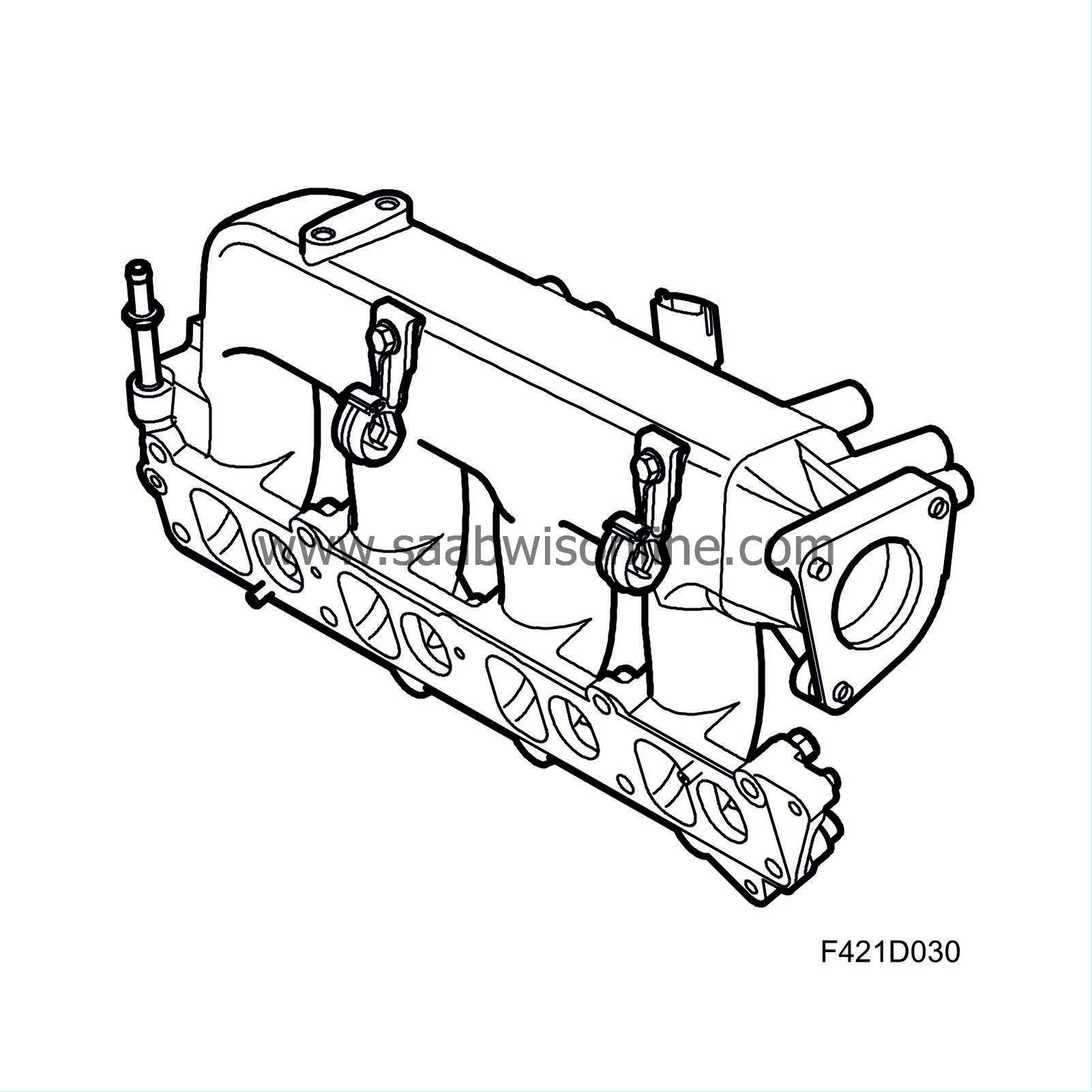
Function at light load, low to moderate engine speed
When driving with a light load, a powerful turbulence is desired during the intake stroke to ensure a good blend of air and fuel. This is difficult to achieve, though, as there a small amount of air flow through the engine during this time. The solution is to increase swirl formation through outside forces. By allowing air to only flow in through the inlet duct that generates strong swirl and blocking the other one, there is strong turbulence even during these conditions. The inlet duct for tumble is blocked by the throttle. Funnily enough, this throttle is called a "swirl throttle" even though it is located in the tumble duct.Function at high load, moderate to high engine speed
When driving at high engine output, the intake air would be choked too much if only one inlet duct were open. So, the swirl throttle opens so that the cylinder is supplied air from both inlet ducts. The result is a considerably higher degree of fullness in the cylinder, allowing ECM to employ more fuel without a significant increase in emissions. The swirl throttle can be opened to any degree, thus the balance of tumble and swirl can be controlled to any degree. The goal is to have a blend of fuel and air that is as good as possible.| Camshaft drive |

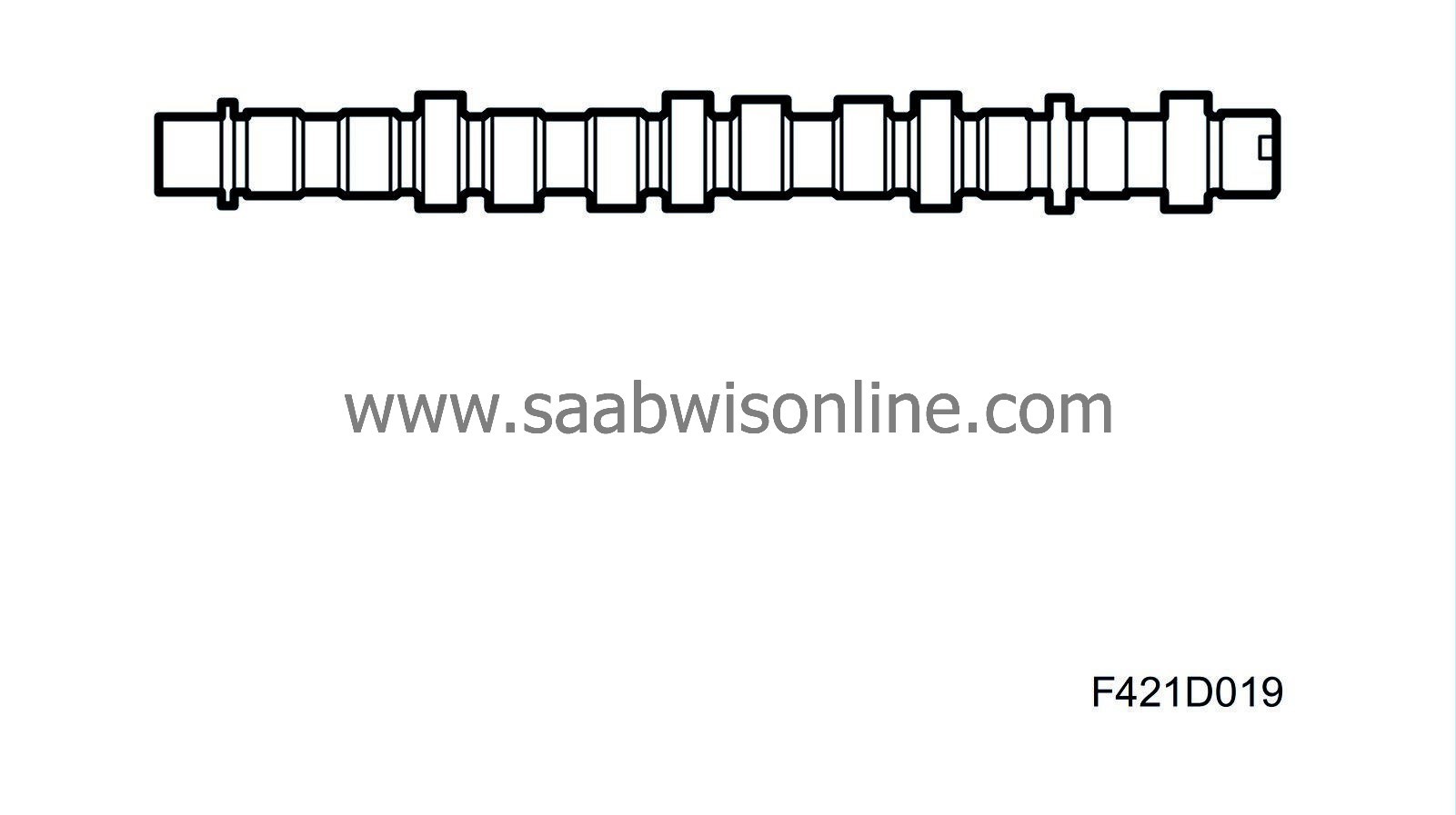
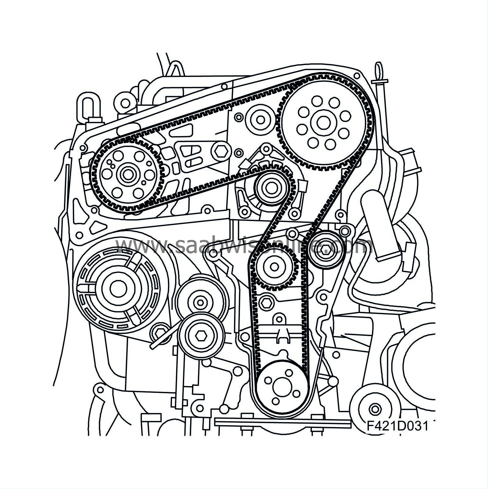
Camshafts
Z19DTH: The engine is equipped with dual overhead camshafts. The exhaust camshaft is driven by a belt with self-adjusting tensioner. The exhaust camshaft houses a sprocket which drives the intake camshaft. The camshafts actuate the rocker arms via a roller bearing mounted on the rocker arm. The need for valve clearance adjustment has been eliminated as this is done continuously via a hydraulic balancer the sits under the valve rocker.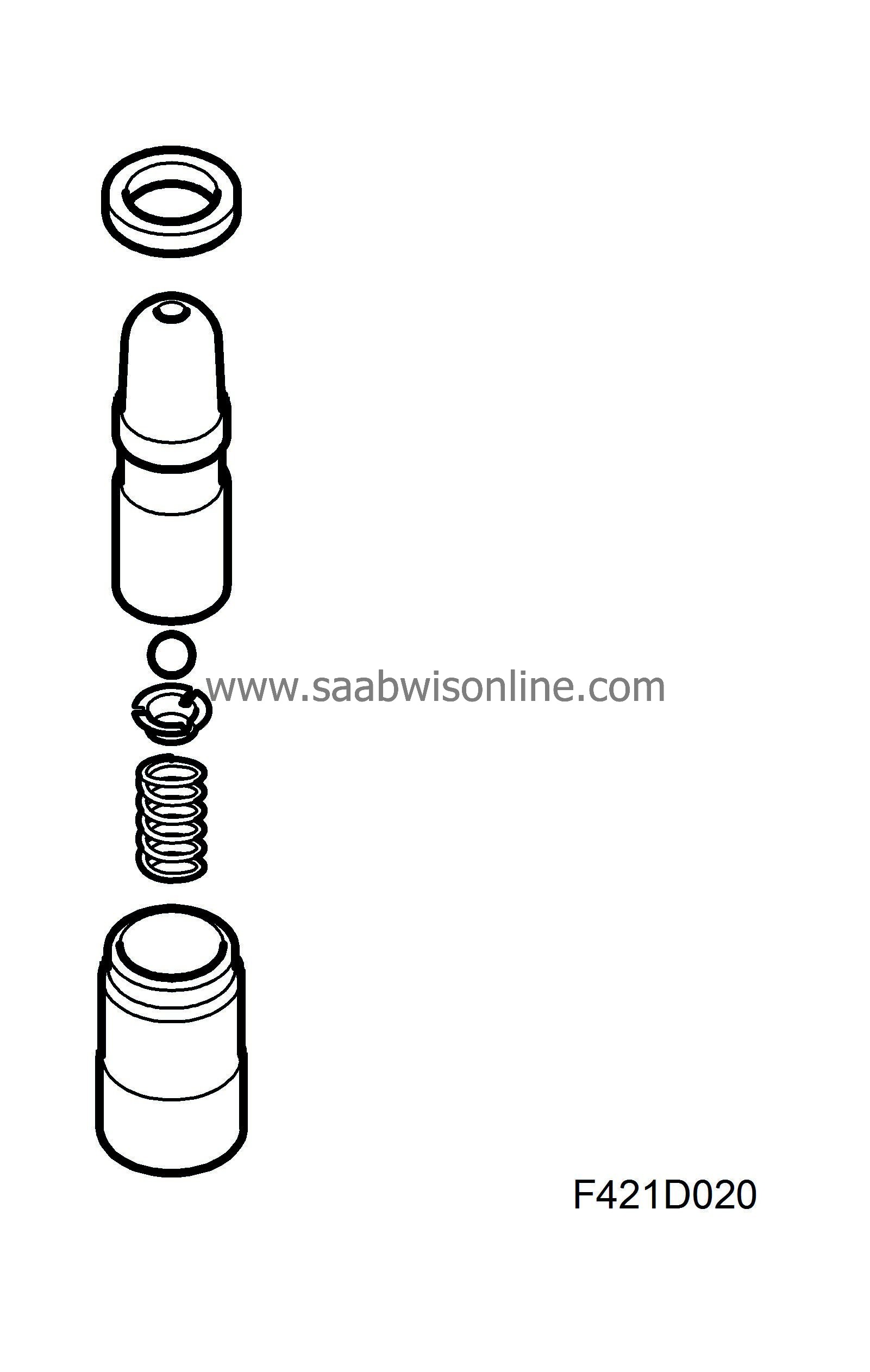
The valve clearance balancer works in an oil bath. It is supplied oil via an oil duct in the cylinder head. The greatest benefits are low friction, quite running and high reliability. The vacuum pump is driven directly by the exhaust camshaft.
.
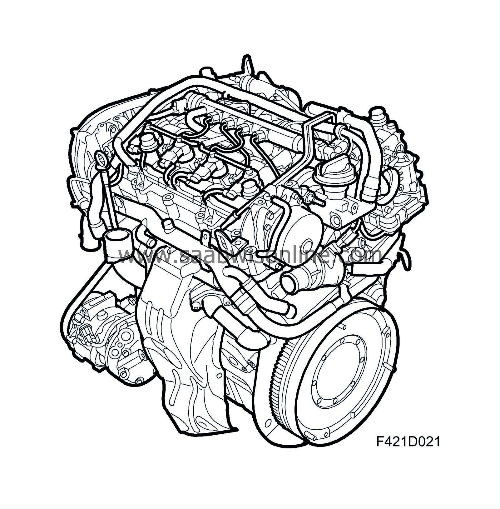
| Lubricating system |
Engine lubrication is handled by a pressure lubricating system. A filter cleans the oil. To keep the oil temperature within appropriate values, the engine is equipped with an engine oil heat exchanger, which is connected to the engine's coolant system.
Oil sump
The oil sump is cast of an aluminium alloy in a robust design to reduce noise. The sump has a baffle plate to reduce the risk of oil splashing up onto the crankshaft and the oil pump drawing air.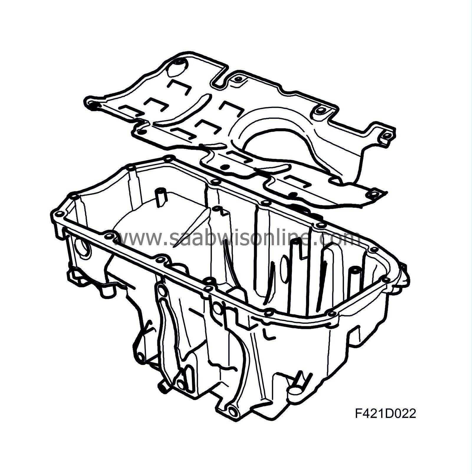
Oil pump
Engine lubrication is handled by a pressure lubricating system in which oil pressure is generated by a gear pump consisting of a pump housing, sprocket and off-centred gear ring. The pump is mounted on the camshaft drive side of the engine and is driven directly by the crankshaft. The pressure relief valve is located in the pump housing. The oil pump sucks oil from the oil pump via a pipe. The oil goes into the gear pump and is pressed out into a duct in the engine to the heat exchanger, after which it is filtered in the oil filter.
Oil filter
To prevent wear and engine damage caused by particles and to reduce engine wear, the engine is equipped with an insert oil filter. The filter cartridge is to be changed as specified in the service programme. If the filter should become clogged and oil has trouble passing through, an overflow valve in the oil filter holder cover will open. The oil then passes without being filtered. This is an "emergency function" when oil must circulate regardless of the condition.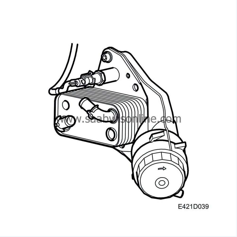
Heat exchanger
Engine oil passes through a heat exchanger to keep it at a more uniform temperature. When the engine is started and the engine oil is cold, the oil is warmed up by engine coolant. When the engine is driven at a high load, i.e. engine oil is hotter than the coolant, the heat exchanger will cool the engine oil. The heat exchanger is mounted on the cylinder block on the rear of the engine together with the oil filter.| Driver circuit for auxiliaries |
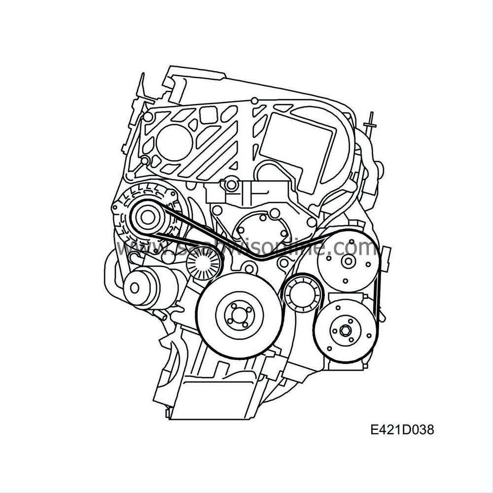
The engine has a belt circuit for auxiliaries. The belt tensioner is automatic and self-adjusting.

The crankshaft pulley has calibrated vibration dampers to dampen the crankshaft resonance (torsional vibrations) and resonance in the auxiliaries circuit. To futher improve the properties of the belt circuit, the generator pulley is a freewheel pulley. The following units are driven by the poly-V belt:
- A/C compressor
- Generator

