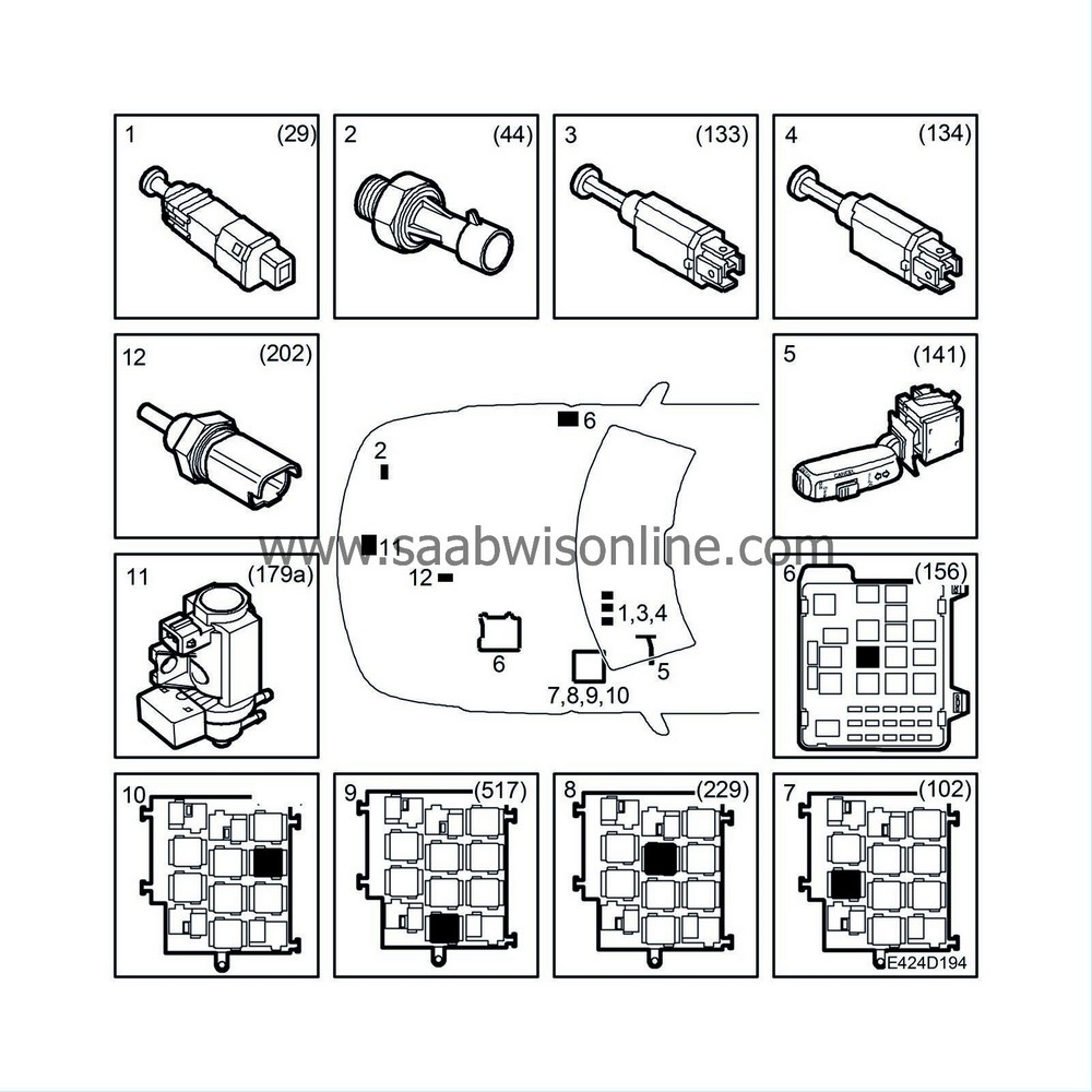
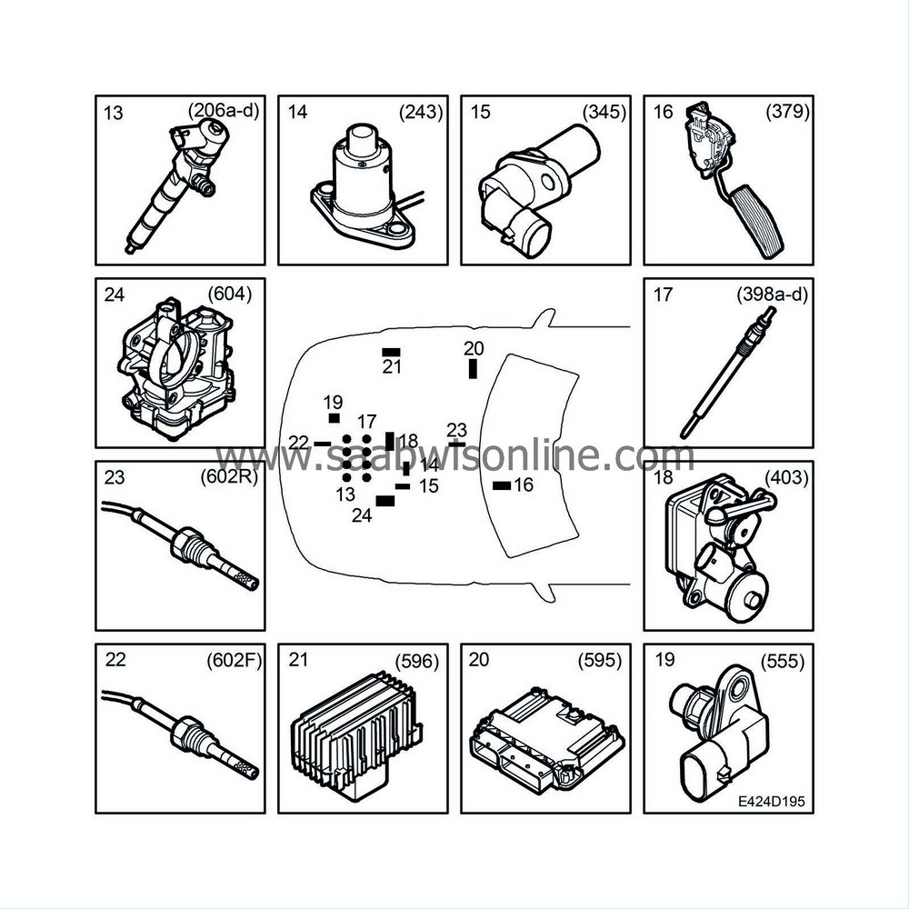
Brief description
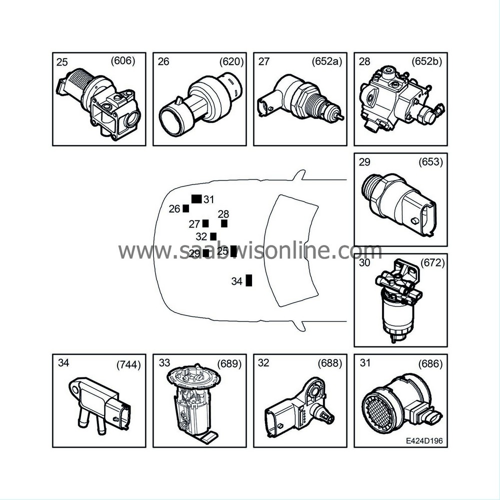
| Brief description |
| 1. |
Switch, brake lights (29)
|
|
| 2. |
Engine oil pressure switch (44)
|
|
| 3. |
Switch, clutch, cruise control (133)
|
|
| 4. |
Switch, brake, cruise control (134)
|
|
| 5. |
Switch, cruise control (141)
|
|
| 6. |
Relay, A/C compressor (156)
|
|
| 7. |
Fuel pump relay (102)
|
|
| 8. |
Main relay, engine management system (229)
|
|
| 9. |
Relay, +50 (517)
|
|
| 10. |
Relay, diesel pre-heating (641)
|
|
| 11. |
Solenoid valve, charge air (179a)
|
|
| 12. |
Coolant temperature sensor (202)
|
|
| 13. |
Injectors (206a-d)
|
|
| 14. |
Level switch, engine oil (243)
|
|
| 15. |
Crankshaft position sensor (345)
|
|
| 16. |
Accelerator pedal position sensor (379)
|
|
| 17. |
Glow plug (398a-d)
|
|
| 18. |
Combustion circulation actuator (403)
|
|
| 19. |
Camshaft position sensor (555)
|
|
| 20. |
EDC16 control module (595)
|
|
| 21. |
Control module, glow plugs (596)
|
|
| 22. |
Front exhaust gas temperature sensor (602F)
|
|
| 23. |
Rear exhaust gas temperature sensor (602R)
|
|
| 24. |
Throttle body actuator (604)
|
|
| 25. |
EGR solenoid valve (606)
|
|
| 26. |
Pressure sensor, A/C (620)
|
|
| 27. |
Fuel pressure control valve, common rail (652a)
|
|
| 28. |
Fuel quantity solenoid valve, high pressure pump (652b)
|
|
| 29. |
Fuel pressure sensor, fuel rail (653)
|
|
| 30. |
Fuel filter unit, diesel (672) contains:
|
|
| • |
Heater element, fuel filter (410)
|
| • |
Fuel temperature sensor (651)
|
| • |
Water level switch, fuel filter (692)
|
| 31. |
Mass air flow sensor unit (686) contains:
|
|
| • |
Mass air flow sensor (205)
|
| • |
Temperature sensor, mass air flow sensor (772)
|
| 32. |
Intake air sensor (688) contains:
|
|
| • |
Intake air temperature sensor (407)
|
| • |
Charge air pressure sensor (603)
|
| 33. |
Fuel pump unit (689) contains:
|
|
| • |
Level sensor, fuel (46)
|
| • |
Fuel pump motor (323)
|
| 34. |
Pressure sensor, particle trap (744)
|
|
| Function |
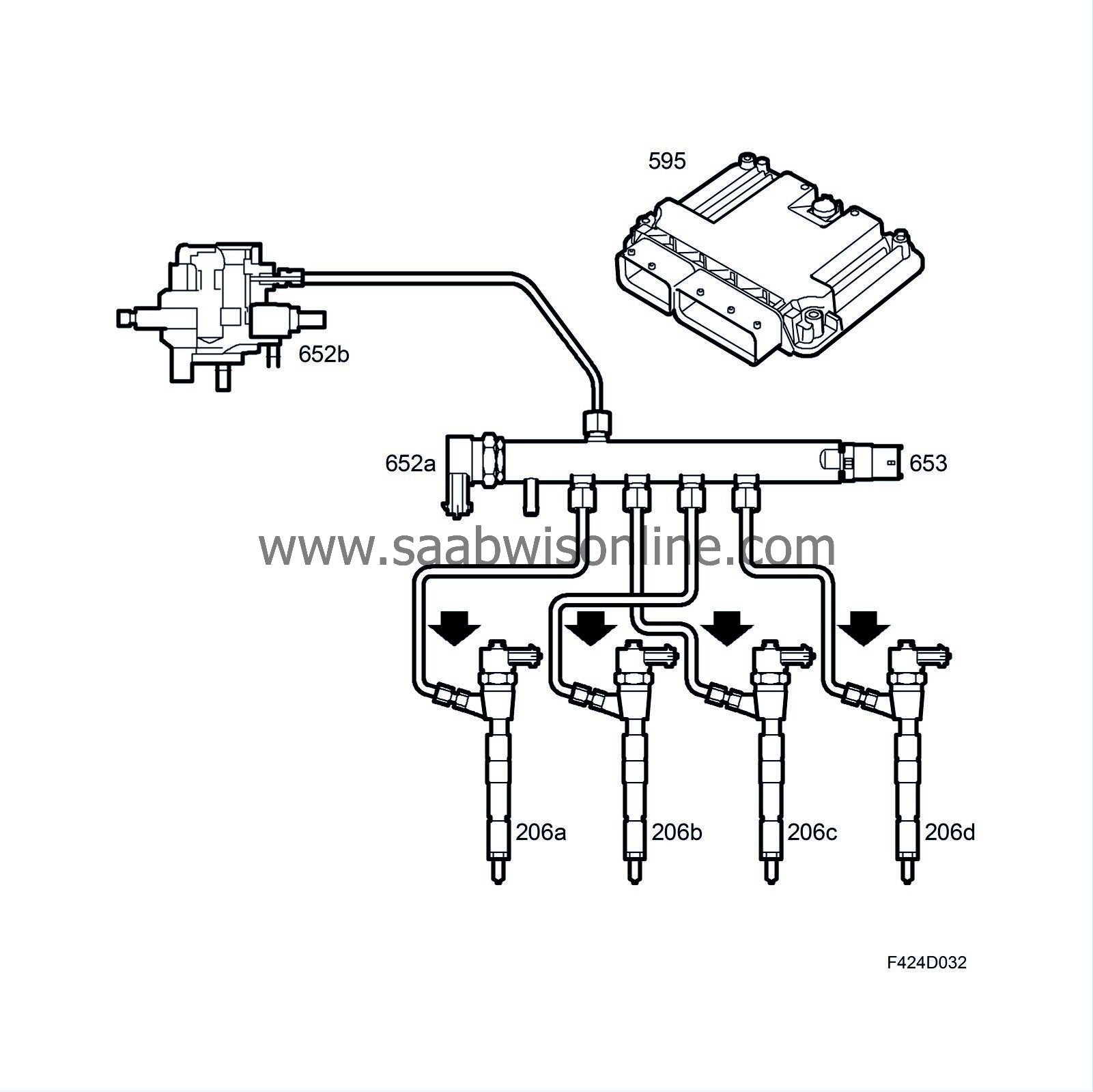
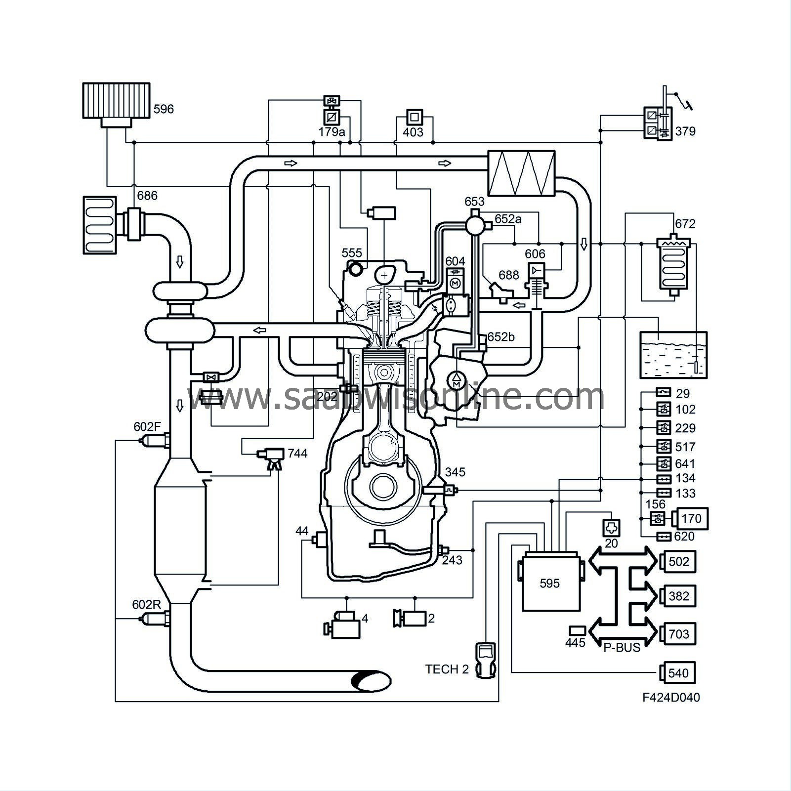
The Bosch EDC16C9 engine management system is used on both the Z19DH and Z19DTH engines, but is calibrated differently for the two variants. The system uses common rail technology. A high-pressure pump feeds a fuel rail to which electronically controlled fuel injectors are connected by pipes.
The software can be updated using SPS.
The main purpose of the engine management system is to control the quantity of fuel injected, injection timing, the turbocharger and engine torque. When the driver depresses the accelerator this affects the pedal position sensor, which is integrated in the pedal bracket. This information (a voltage) is sent to the ECM, which converts it to a request for engine torque from the driver. The torque request is processed by the ECM with regard to the current operating conditions and limitations. The result is an air mass request to produce the torque requested by the ECM.
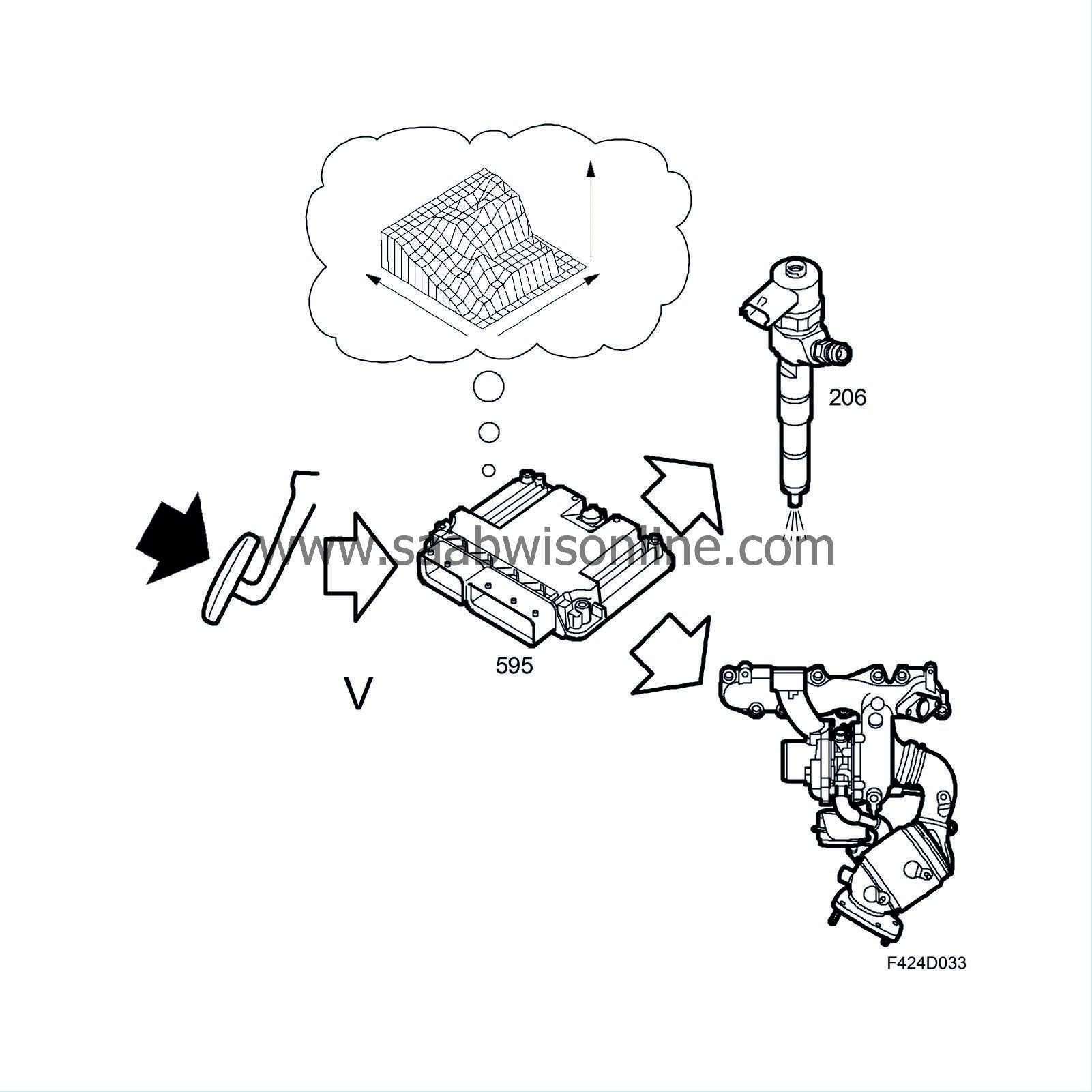
The engine torque is roughly determined by the quantity of injected fuel. To minimise emissions, the ECM controls the air flow. Too little air produces black smoke. To avoid this, there is a smoke limitation function that limits the fuel quantity.
The quantity of injected fuel is controlled by regulating the fuel pressure, injection period and injection timing (crankshaft position). The control module calculates the quantity per combustion that is ideal for the exact present driving conditions, taking into regard emissions, engine durability, driveability and fuel consumption.
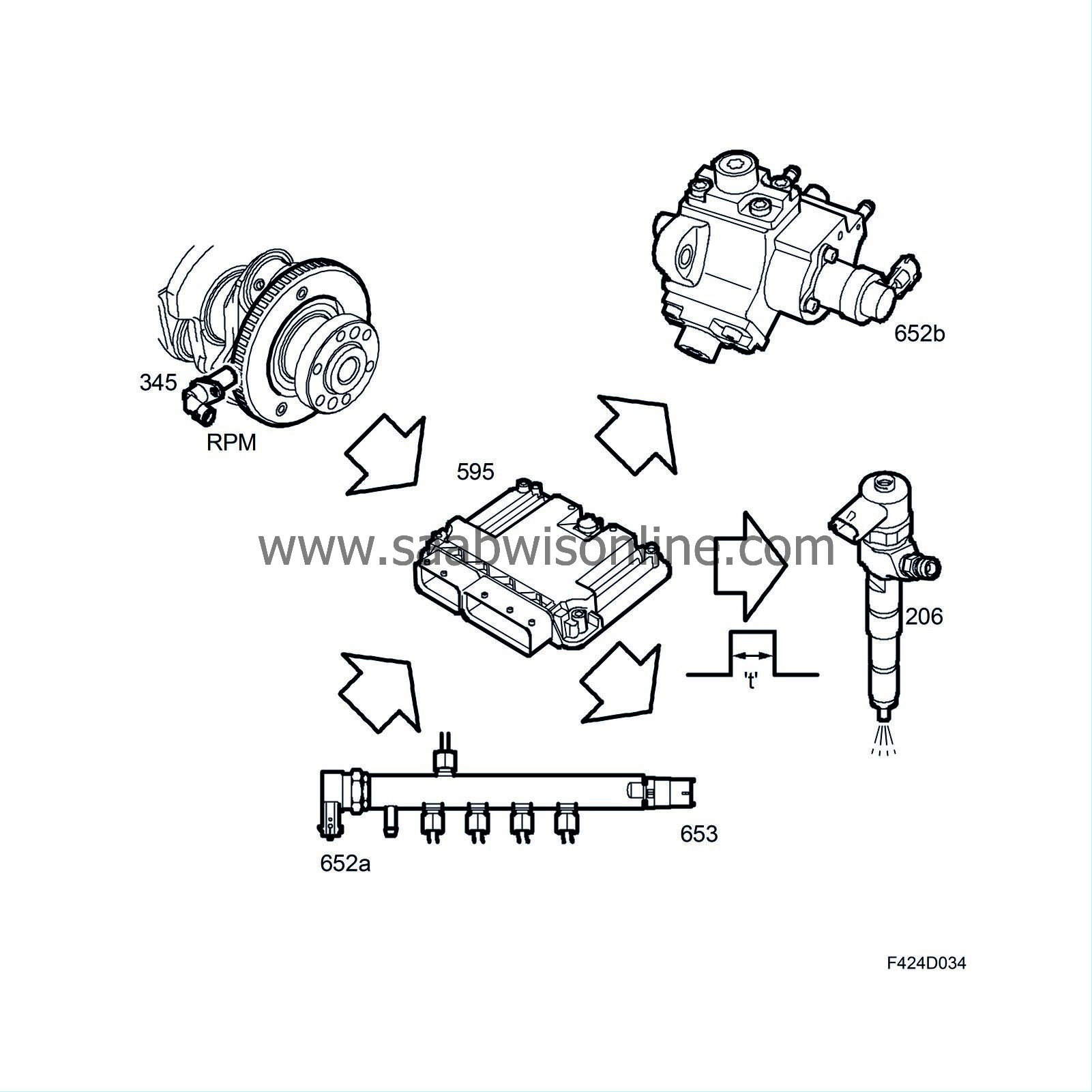
The engine uses pilot injection to reduce engine noise at low coolant temperatures. A small amount of fuel is injected immediately before the main injection. This function is active at coolant temperatures below +60°C.
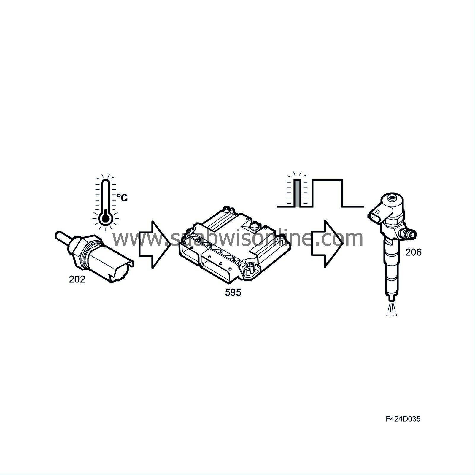
| Description |
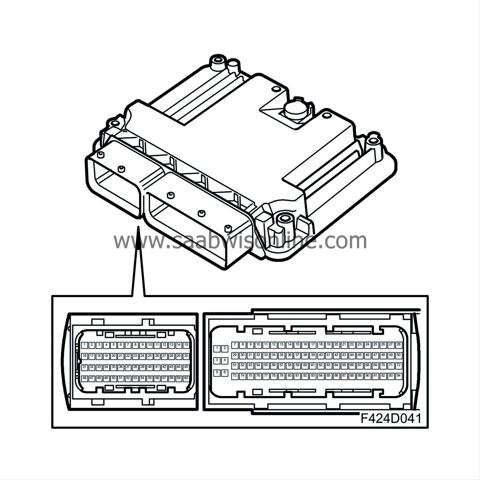
EDC16 control module (595)
The ECM reads the driver's requested power output (torque request) and with the help of several sensors, it calculates the permissible amount of fuel to use in mg/combustion.Its internal diagnosis can be read directly using the diagnostic tool.
ECM also reads the digital information from the cruise control system switch and, if requested by the driver, the engine control module will control the speed of the car.
The radiator fan speed is controlled by ECM.
Generator (2)
The ECM controls the charge from the alternator and compensates for its torque load.When the ECM has registered that the engine has started by calculating the engine speed signal, charging will start.
Switch, brake lights (29)
The switch informs ECM of the brake pedal position. It is used to turn off cruise control.Engine oil pressure switch (44)
If there is no oil pressure, the switch closes and makes a ground to the ECM which in turn sends out the bus message "no oil pressure" to the MIU and SID.Fuel pump relay (102)
The relay is activated by the ECM when it is time to start the fuel pump.Switch, clutch, cruise control (133)
The switch informs ECM of the clutch pedal position. It is used to turn off cruise control.Switch, brake, cruise control (134)
The switch is used to carry out a feasibility assessment of the brake light switch. It is also used to turn off the cruise control.Switch, cruise control (141)
With help of the integrated cruise control switch (141) the driver can request that ECM should maintain vehicle speed alternatively reduce or increase the set vehicle speed.Relay, A/C compressor (156)
The relay turns the A/C compressor on and off after receiving a command from the ECM. The ECM compensates for the increase/decrease in engine torque required.Solenoid valve, charge air (179a)
The solenoid valve controls the charge air with vacuum from the vacuum pump. The engagement period is controlled by a PWM signal from the ECM.Temperature sensor, coolant, engine management system (202)
The temperature sensor measures the engine temperature. The ECM uses the reading to deliver more fuel to the engine when the engine is cold. In addition, it can protect the engine against harmful overheating because the control module will limit the amount of fuel if there is a risk of overheating. The speed of the radiator fans is controlled by the engine temperature.Injectors (206)
Inject the fuel quantity calculated by the ECM into the cylinder.Main relay, engine management system (229)
The relay controls the power supply to the majority of components in the engine management system.Level switch, engine oil (243)
The sensor switch breaks when the oil level is too low. The ECM confirms the low level by evaluating the time that the switch is open.The ECM then sends the bus message "Oil level low" to the SID. This information from the oil sensor is a filtered value that depends on the temperature, engine speed, acceleration and vehicle speed, which together give a mean value for the oil level.
Crankshaft position sensor (345)
The position sensor sends an alternating current, the frequency of which is proportional to the engine speed. Each pulse is used by the ECM to calculate when the engine is at top dead centre.Accelerator pedal position sensor (379)
The position sensor has two potentiometers that inform the ECM of the driver's torque request.Glow plug (398)
Provide the fuel, when necessary, with the correct ignition temperature.Swirl throttle actuator (403)
The actuator controls the vacuum that controls the swirl throttle.Relay, +50 (517)
When the ECM has checked that all start conditions are fulfilled, it activates the relay, which starts the starter motor.Camshaft position sensor (555)
The position sensor keeps check of the camshaft position to determine which cylinder is next for ignition.Control module, glow plugs (596)
The control module supplies power to the glow plugs on request from the engine control module. It also reduces the power to the glow plugs when the engine has started. The glow plug control module has internal diagnostics, the result of which is sent through a lead to the ECM, where any diagnostic trouble codes can be read.Exhaust temperature sensor (602)
Measures the temperature of the exhaust gases before and after the catalytic converters.Throttle body actuator (604)
Controls the air mass supplied to the combustion chamber.EGR solenoid valve (606)
The ECM controls the activation period of the solenoid valve with a PWM signal. The EGR function means that the ECM commands the EGR to return a certain quantity of exhaust gases to achieve the mg/combustion calculated by the control module.Pressure sensor, A/C (620)
Measures the prevailing pressure on the high-pressure side of the A/C system.Used for load compensation and radiator fan operation. The value is sent as a bus message for use by the ACC.
Relay, pre-heating (641)
The ECM activates the relay when fuel pre-heating is required in the fuel filter.Fuel pressure control valve, common rail (652a)
When the pressure in the fuel rail is higher than the required pressure, the ECM opens the solenoid valve, releasing excess fuel into the return line.Fuel quantity solenoid valve, high pressure pump (652b)
The valve controls the quantity of fuel supplied to the high-pressure pump, especially at low engine speeds.Fuel pressure sensor, fuel rail (653)
The fuel rail pressure is measured by the pressure sensor so that ECM can regulate the pressure in the fuel rail and thereby the amount of fuel to the injector.Fuel filter unit (672)
The unit comprises a heating element, fuel filter (410), temperature sensor, fuel level switch (651) and water level switch (692).The heating element pre-heats the fuel as necessary. The ECM controls heating based on the reading from the temperature sensor.
When there is too much water in the filter, the level switch warns of this.
Mass air flow sensor (686)
The unit contains a mass air flow sensor (205) and temperature sensor (772).The mass air flow sensor measures the mass air flow to the engine. The ECM calculates the intake air mass per combustion based on the mass air flow.
The temperature sensor measures the temperature of the intake air.
Sensor, intake air (688)
The combined pressure and temperature sensor measures the temperature and pressure of the intake air.The pressure sensor measures the pressure in the intake manifold so that the ECM can control the turbocharger boost pressure.
The temperature sensor measures the temperature of the intake air so that the ECM can request the correct quantity of air for combustion (hot air requires a high volume).
Fuel pump unit (689)
The fuel pump unit comprises a fuel level sensor (46) and fuel pump (323).The level sensor measures the amount of fuel in the tank.
The fuel pump supplies fuel at low pressure to the high-pressure pump.
Pressure sensor, particle trap (744)
To determine when the particle trap is full and requires emptying, the pressure sensor measures the pressure difference over the trap.| Principles of operation, 4-stroke diesel engine |
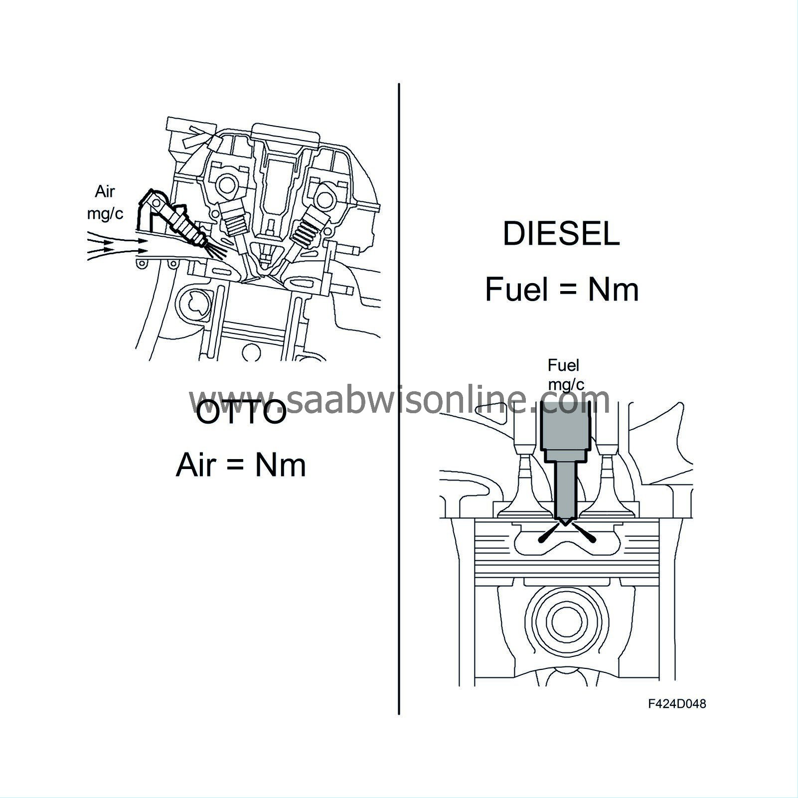
Differences between Otto and diesel engines
The major differences between a conventional Otto engine and diesel engine are the fuel supply to the engine, ignition system and compression ratio.Otto engine
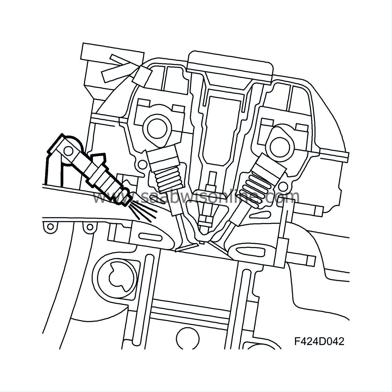
| • |
Fuel is supplied mixed in the intake air
|
|
| • |
Ignition with an electrical spark
|
|
| • |
Relatively low compression ratio (generally between 8:1 - 12:1)
|
|
Diesel engine
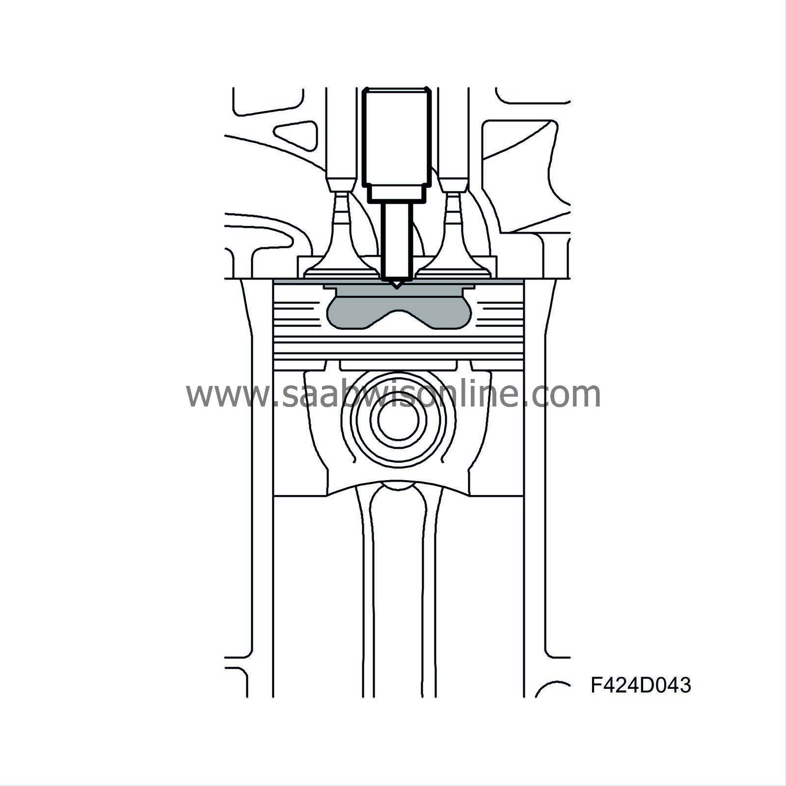
| • |
Fuel supplied directly into the combustion chamber where it mixes with the air
|
|
| • |
Ignition through the heat of compression
|
|
| • |
Relatively high compression ratio (generally between 16:1 - 22:1)
|
|
The four strokes
Diesel engines have four strokes: intake stroke, compression stroke, power stroke and exhaust stroke.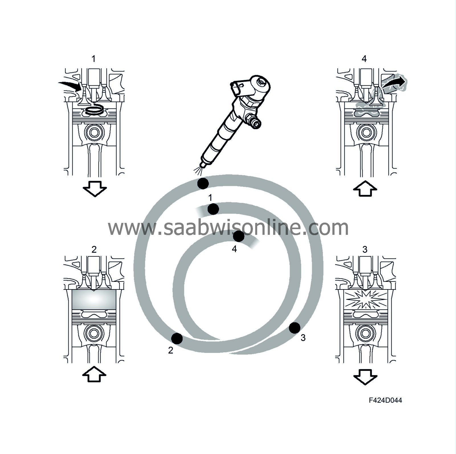
During the intake stroke, air is fed into the cylinder. The design of the inlet ducts means the air swirls violently in the cylinder. The intake valve close and the compression stroke starts.
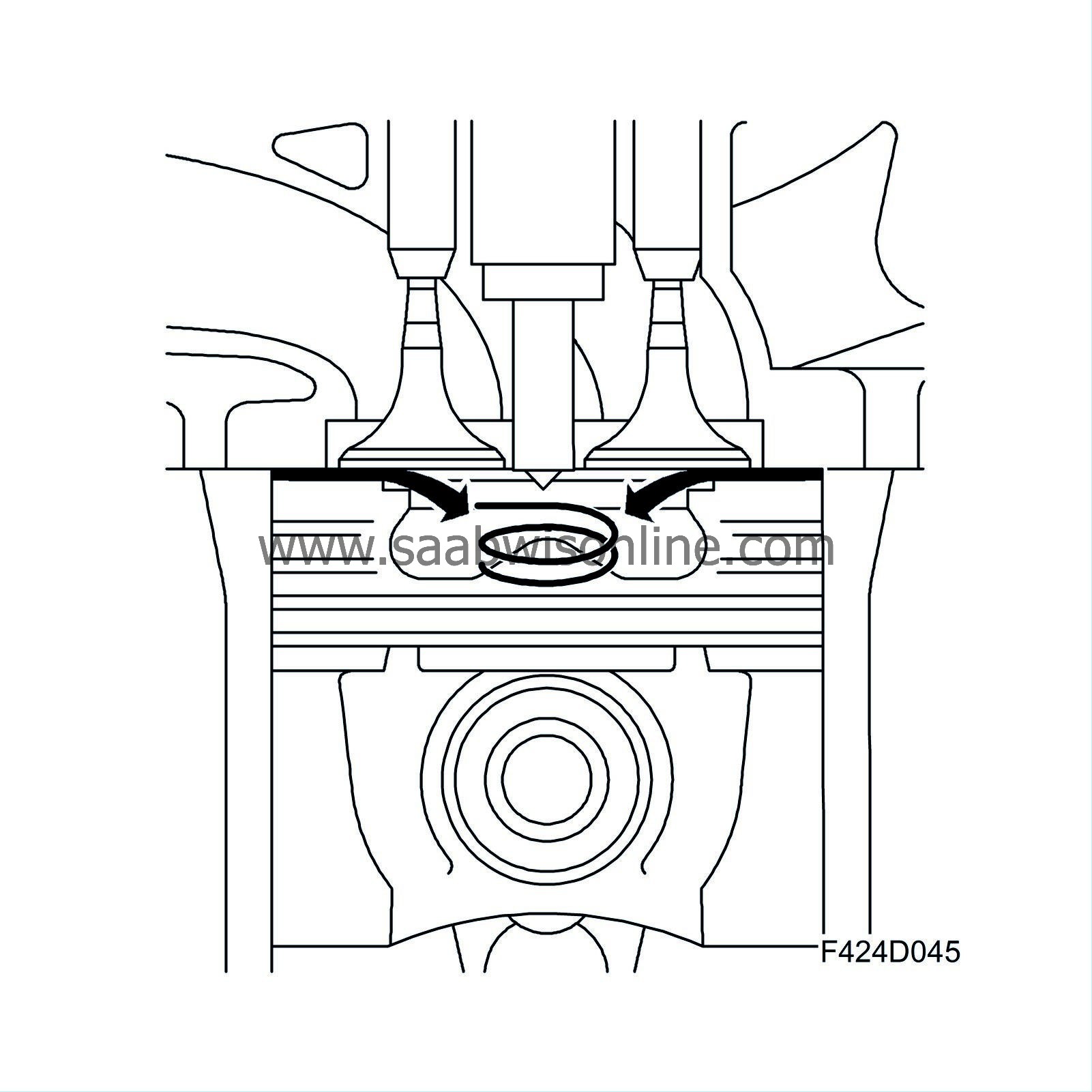
The enclosed air mass is now compressed. The pressure and temperature rise. The upward movement of the piston affects the movement of air. At the end of the stroke, virtually all air is forced into a space in the piston (combustion chamber). This movement of air from the extremities to the combustion chamber increases the air speed. At the end of the compression stroke, fuel is added at high pressure (up to 16 MPa/160 bar).
Combustion in a diesel engine takes place when the correct quantity of fuel is added to a mass of air at high temperature and pressure. After a slight delay, the fuel combusts. The delay primarily depends on the current pressure, temperature, cetane rating and how well the fuel mixes with the air. Ideally, this delay should be short to ensure smooth, quiet running.
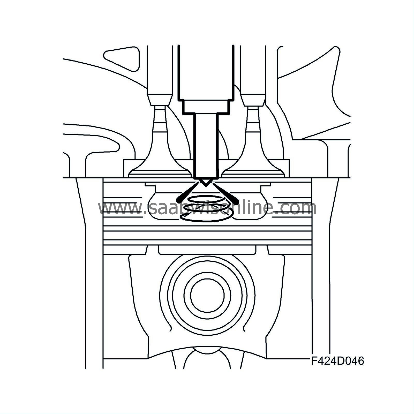
The piston has now changed direction. The fuel is ignited and the gases expand violently. This is the power stroke. The pressure in the cylinder is converted to work. Just before the piston reaches bottom dead centre, the exhaust valve opens and the exhaust gases are led out through the exhaust manifold to the turbocharger. The process is repeated.
Efficiency
Diesel engines are significantly more efficient that conventional Otto engines. There are several reasons.
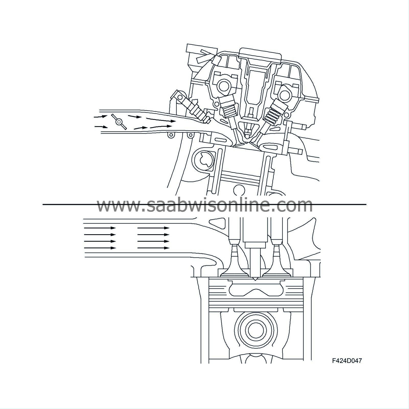
The absence of a throttle means that the engine is aspirated without restrictions in the air intake system, thus reducing pump losses. A higher compression ratio means greater efficiency. It is however not possible to increase the compression ratio indefinitely since at a certain point the losses will outweigh the gains, thus reducing efficiency. A turbo with VNT turbine reduces the exhaust counter pressure compared to a turbocharger with fixed turbine geometry and waste gate control. Lower exhaust counter pressure means lower pump losses.
Torque control
Engine torque is controlled by supplying the correct quantity of fuel and then adding the correct mass of air. Otto engines work in the reverse: air mass produces torque, and the fuel quantity is based on the mass of air.