Detailed description, fuel system
| Detailed description, fuel system |
| Fuel tank |
The fuel tank is made of plastic. The tank also contains an integrated fuel level sensor and feed pump.
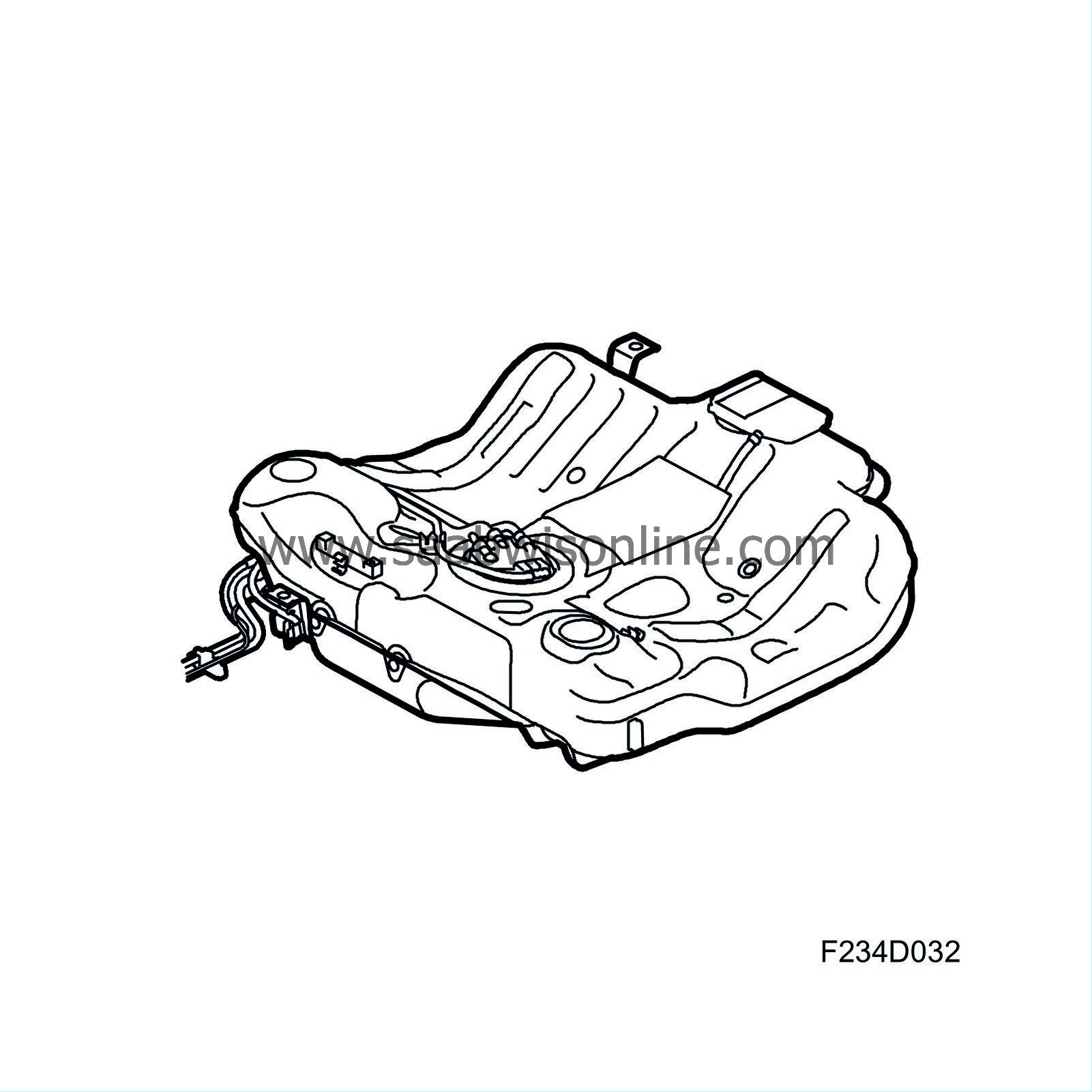
| Feed pump integrated in fuel tank |
An electric feed pump is mounted in the fuel tank. This delivers fuel to the high pressure pump. Fuel pressure is 4 bar.
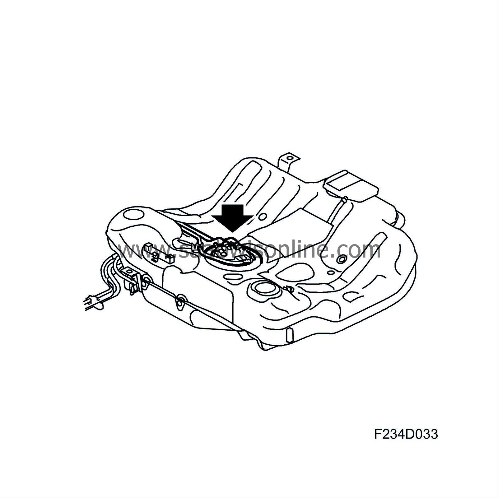
| Fuel lines |
The delivery line supplies fuel to the pressure pump. The return line is for return fuel. The lines are made of plastic and steel.
| Fuel filter |
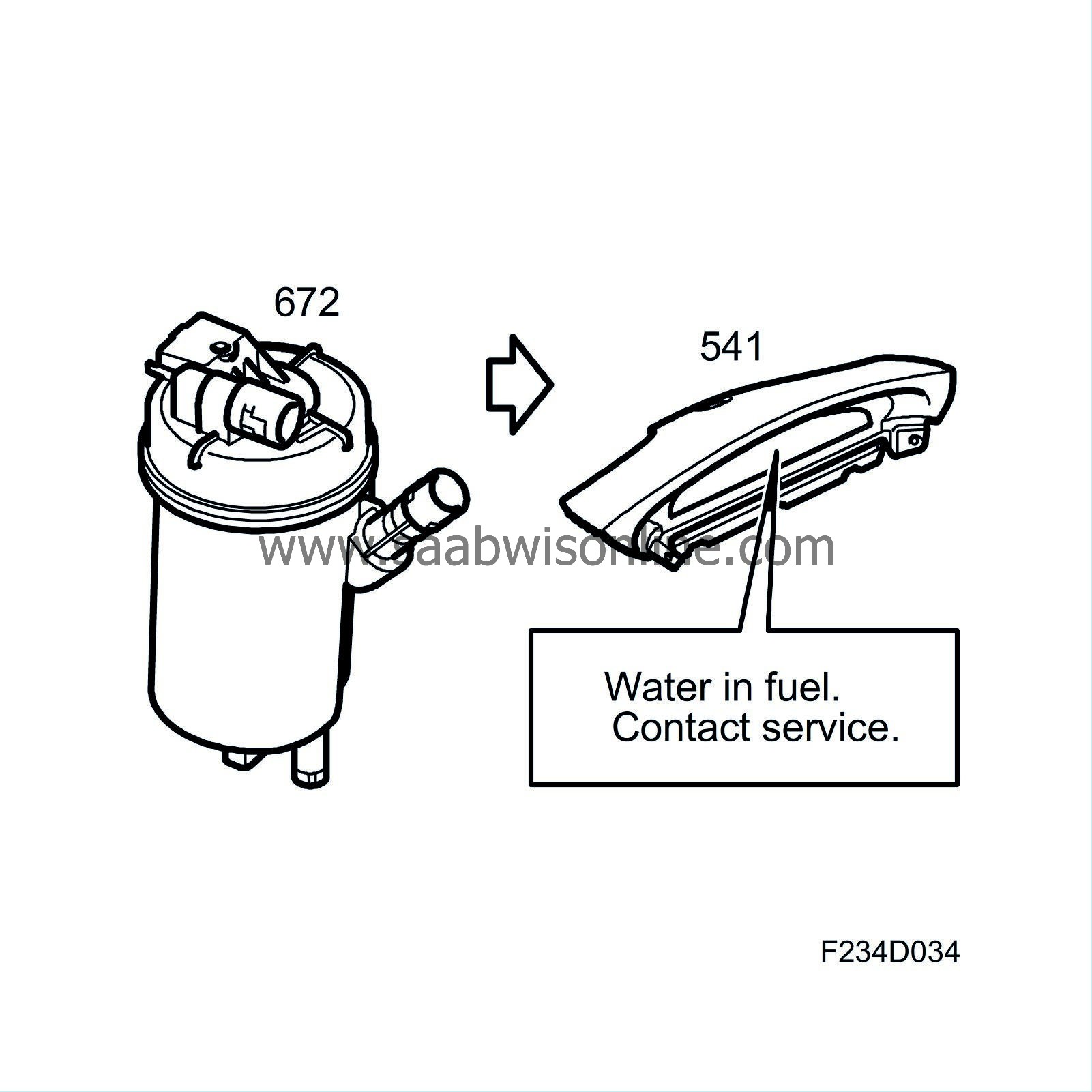
The main task of the fuel filter is to prevent contaminants from entering the fuel system. The size of the pores in the filter is 3-5 micrometres. The filter also contains a sensor to detect the presence of water in the fuel. The filter holder also contains a preheating element and fuel temperature sensor.
If the amount of separated water exceeds 60 ml, the driver is warned of such via the following message in the main instrument unit: Water in fuel. Contact workshop. The filter can hold no more than 100 ml of water. The fuel filter, which is a spin-on type, is located on a bracket on the left side of the tank.
| High-pressure pump |
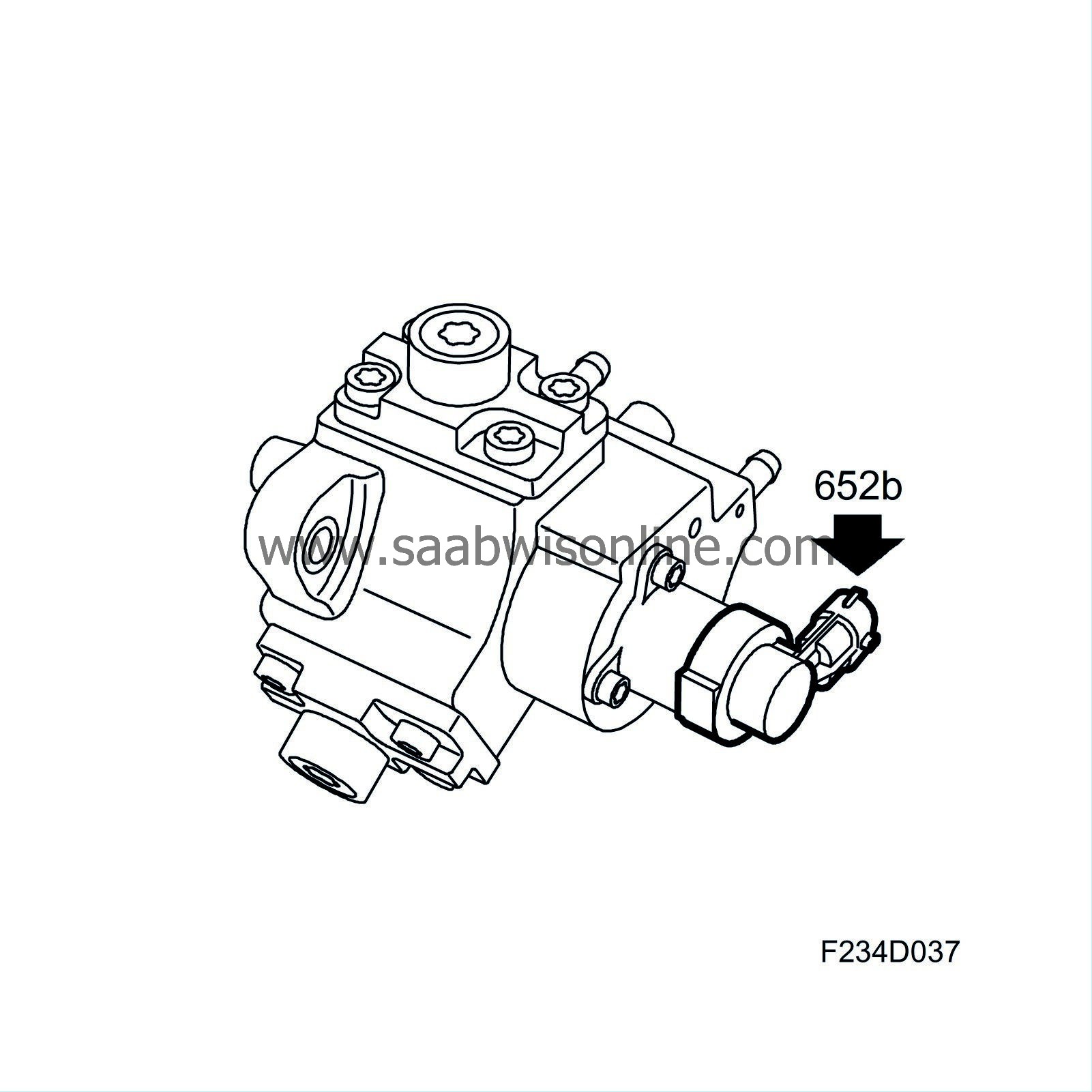
The three-cylinder high pressure pump generates injection pressure, which can reach about 160 MPa (1600 bar). As the engine's fuel need changes over a large range, the fuel pressure delivered to the fuel rail by the high pressure pump must be regulated. This is done by the fuel control valve (652b), which is mounted on the high pressure pump, and the fuel pressure control valve (652a), which is located on the right side of the fuel rail.
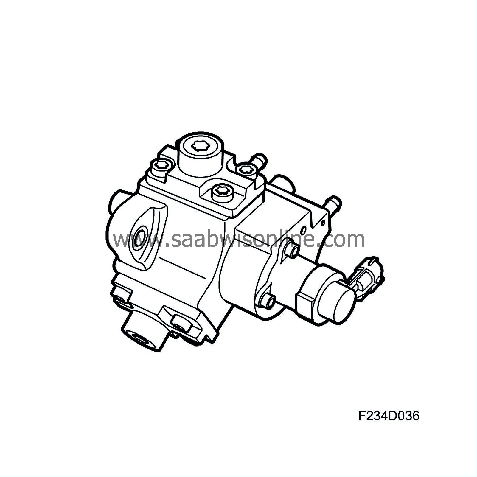
The fuel control valve (652b) on the high pressure pump is used to choke the fuel supply to the pump's inlet side. When fuel need is low, the pump's supply is choked so that the cylinders are not filled completely. Thus, pump capacity is regulated, which reduces its output need. Regulation via the valve (652b) is preferably done at a speed over idling speed. The high pressure pump is driven by the camshaft drive and has specific relationship to the crankshaft. Be aware of this when replacing a timing belt or the high pressure pump.
| Fuel quantity solenoid valve, high pressure pump (652b) |
The fuel control valve (652b) regulates fuel quantity to the high pressure pump. This prevents the high pressure pump from working at full capacity (will completely filled pump chamber) when fuel needs are low. ECM regulates the valve and measures the result in the form of fuel pressure attained in the fuel rail. The PWM signal is corrected if necessary to obtain the requested pressure. At present, the valve, which is mounted on the high pressure pump, cannot be replaced separately. If the valve is faulty the entire unit, comprising the high pressure pump and valve, must be replaced.
| Fuel rail/reservoir |
The fuel rail/reservoir distributes fuel to the four cylinders and serves as a reservoir to reduce the pulsations of the fuel pressure. The fuel rail has connections for the high-pressure fuel from the high pressure pump and return fuel. A pressure sensor is mounted on the left side of the fuel rail while the fuel pressure control valve (652a) is mounted on the right. The fuel rail has a capacity of 20 cm 3 .
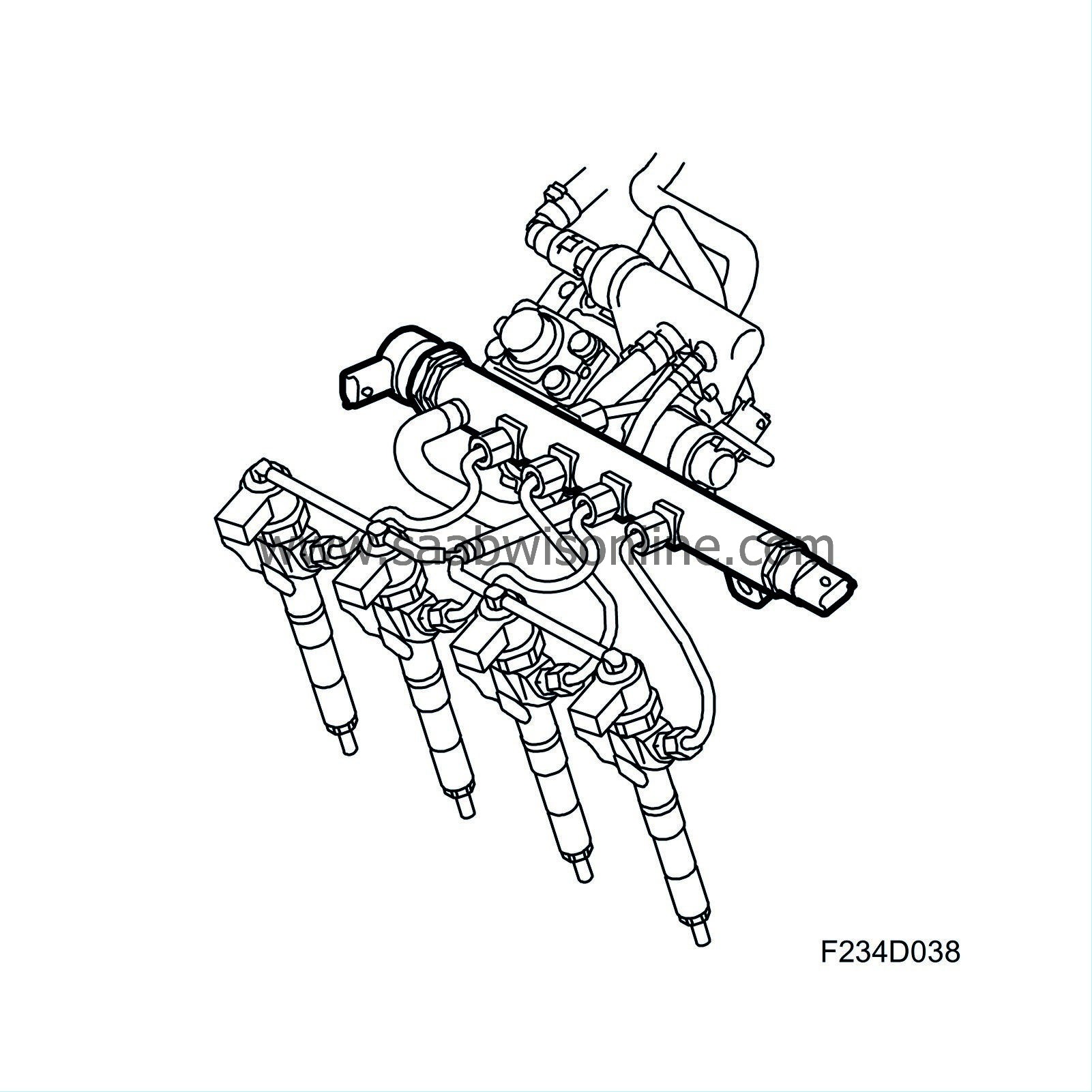
The volume, shape and location of the connections have been thoroughly tested to prevent disruptions in the form of fuel pressure pulsation, which would cause unequal distribution of fuel to the four nozzles.
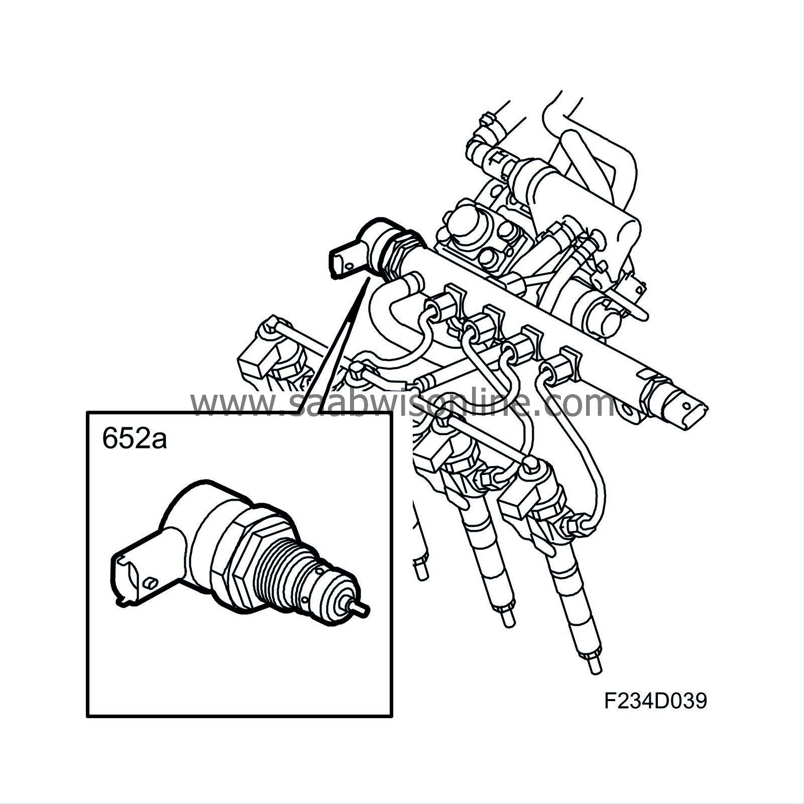
| Fuel pressure control valve, common rail (652a) |
The pressure sensor (652a) is mounted on the right side of the fuel rail. The valve controls the pressure in the fuel rail and is regulated by ECM.
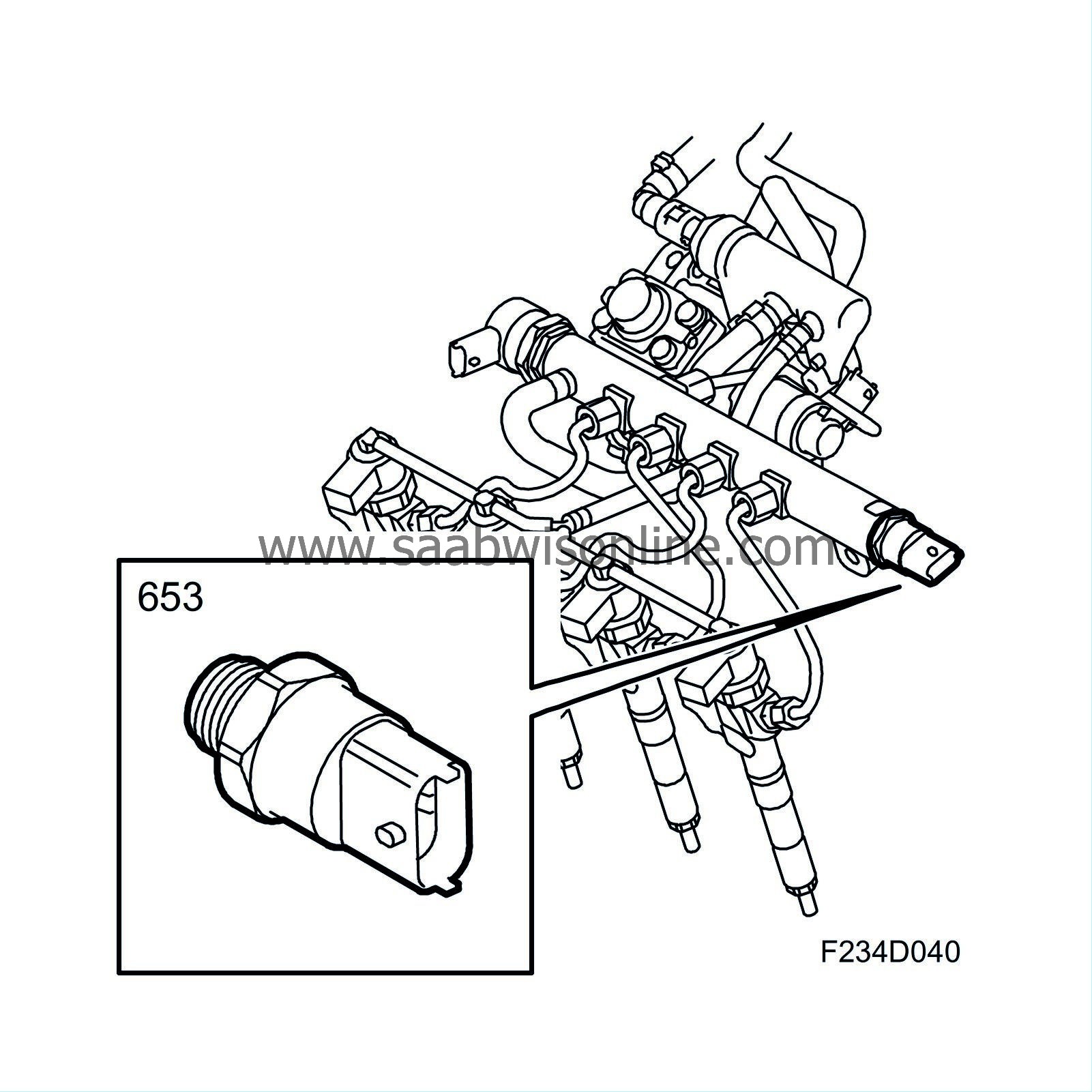
| Fuel pressure sensor, fuel rail (653) |
The fuel pressure sensor (653) is mounted on the left side of the fuel rail. It measures fuel pressure so that the engine management system knows when the request pressure has been attained. It is regulated by ECM with +5 V and output voltage within the area is 0.5-4.5 V. Upon replacement of the pressure sensor, the diagnostic tool must be connected to restore the adaptation values. Select Menu - Engine - Engine management system - Adjustment - Fuel Pressure Sensor Replaced.
| High pressure pipe |
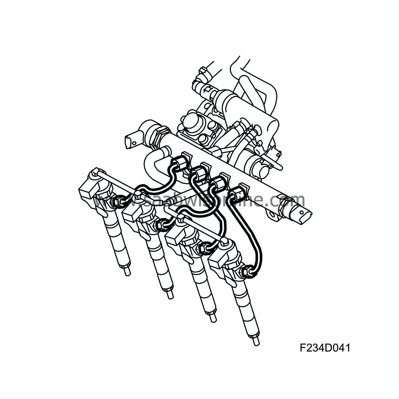
The high pressure pipe is a connection pipe between the fuel rail and injector. The high pressure pipe is made of steel.
| Injectors |
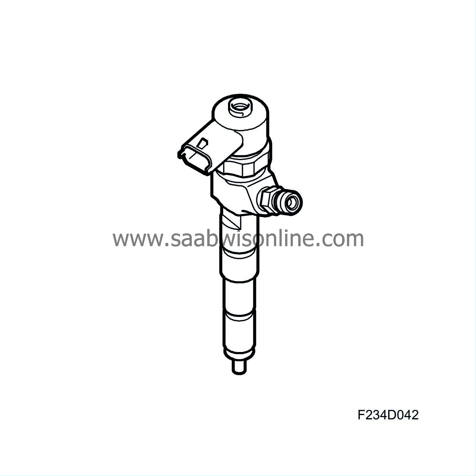
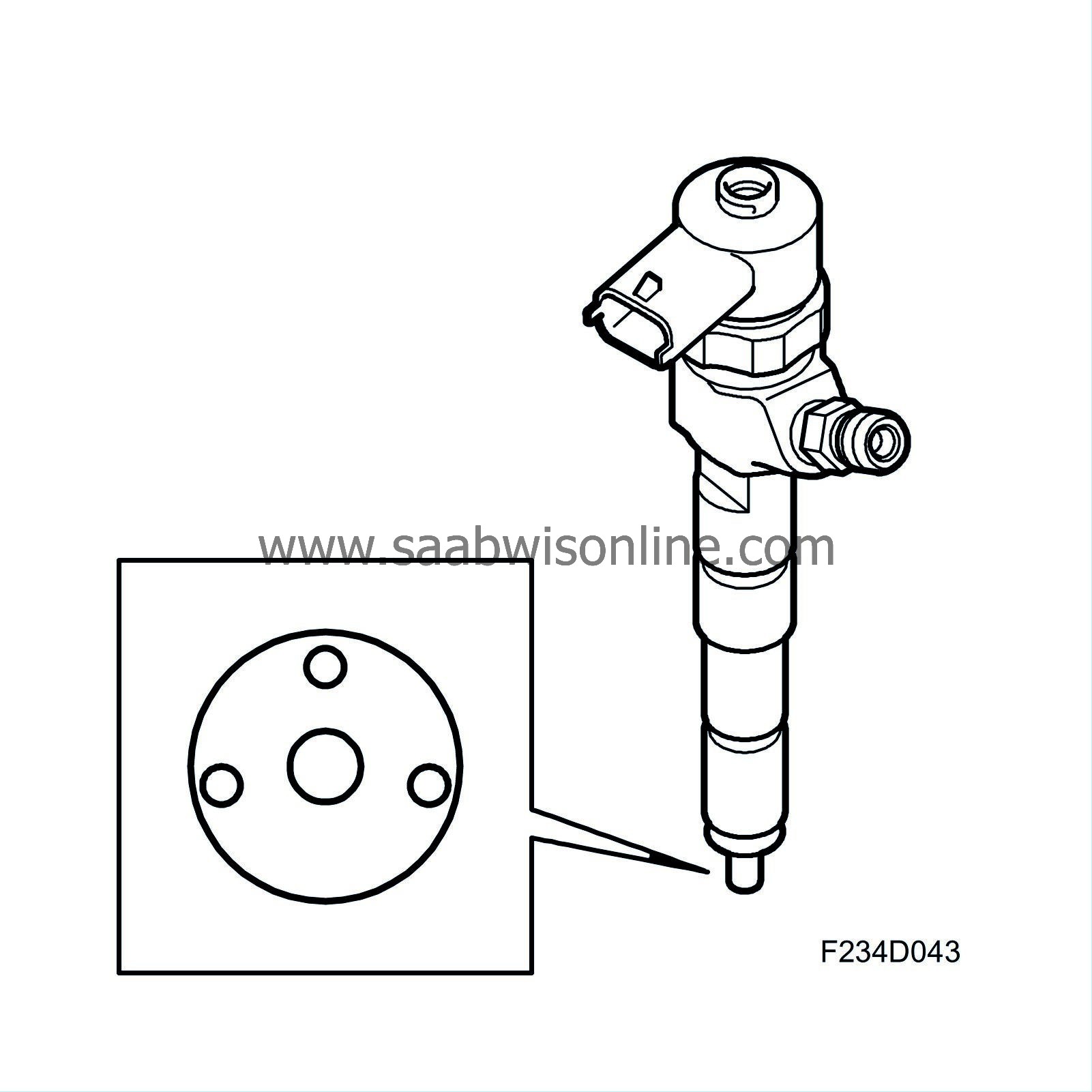
Electrically regulated injectors (206a-d) that inject fuel into the combustion chambers. The injectors have seven holes, thus there are seven jets of fuel. Each hole has a diameter of 0.141 mm. As a means of comparison, an ordinary strand of hair is 0.08 mm. The small diameter of the holes is necessary to distribute the fuel in small drops. Some manufacturing tolerances are just a few thousandths of a mm. Thus, it is vital that no dirt enters the fuel system.
The injectors, which are low ohm injectors, are regulated by ECM following the "peak and hold" principle. An opening pulse is sent first with a stream that is rather high (peak) in order to generate a quick reaction in the injector. Once a certain amount of time has passed, the nozzle is considered open and the ECM limits the flow (hold). ECM can inject fuel up to five times per power stroke with a maximum injection duration of about 1 ms - shorter than the blink of an eye.
Injection quantity is for example 1 mm 3 for the pilot injection. Compare this to a raindrop, which has a volume of about 30 mm 3 . The injector is on par with a precision instrument.
| Important | ||
|
If the injectors are to be refitted, mark the injectors so that they can be refitted to the same cylinder. |
||
| Important | ||
|
If new injectors are to be fitted, read and make a note of its classification code. The code is to be used when programming using the diagnostic tool. |
||
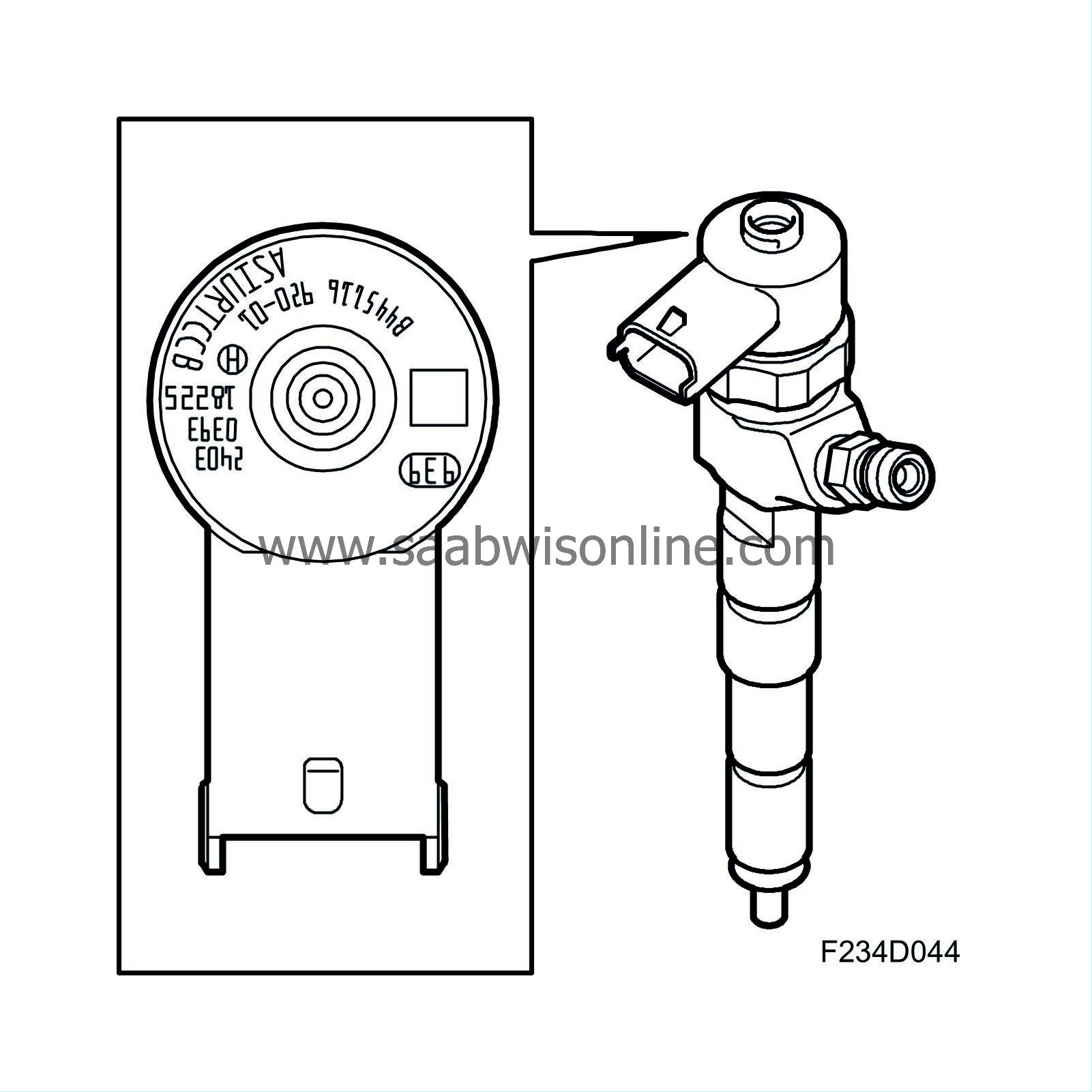
During manufacture, the injectors are given a final inspection and then are assigned a classification code based on their properties. This code describes the nozzle's properties for the control module. If an injector is replaced, the diagnostic tool must be connected for programming. Select Menu - Engine - Engine management system - Adjustment - Injector Replaced. Then enter the classification code.
| Return hoses/pipes |
The hoses handle leak fuel from the injectors. There is controlled leakage in the injectors and this is lead back to the fuel tank via the return fuel hoses, return fuel tank and then the return fuel line.
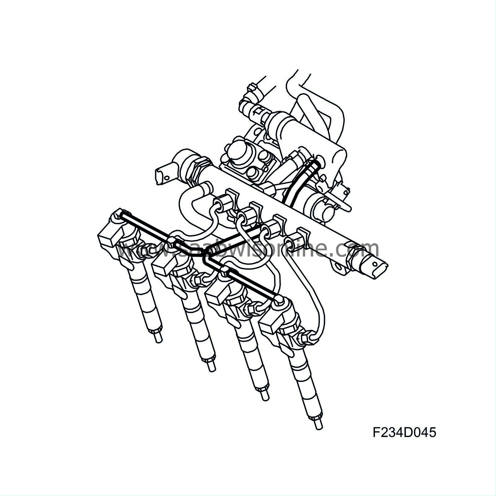
| Return fuel tank |
Container in which return fuel from the high pressure pump, fuel rail and injectors is collected. A line known as the return line runs from the return fuel tank to the fuel tank- Of the fuel delivered to the high pressure pump, about three quarters returns via the return fuel tank.
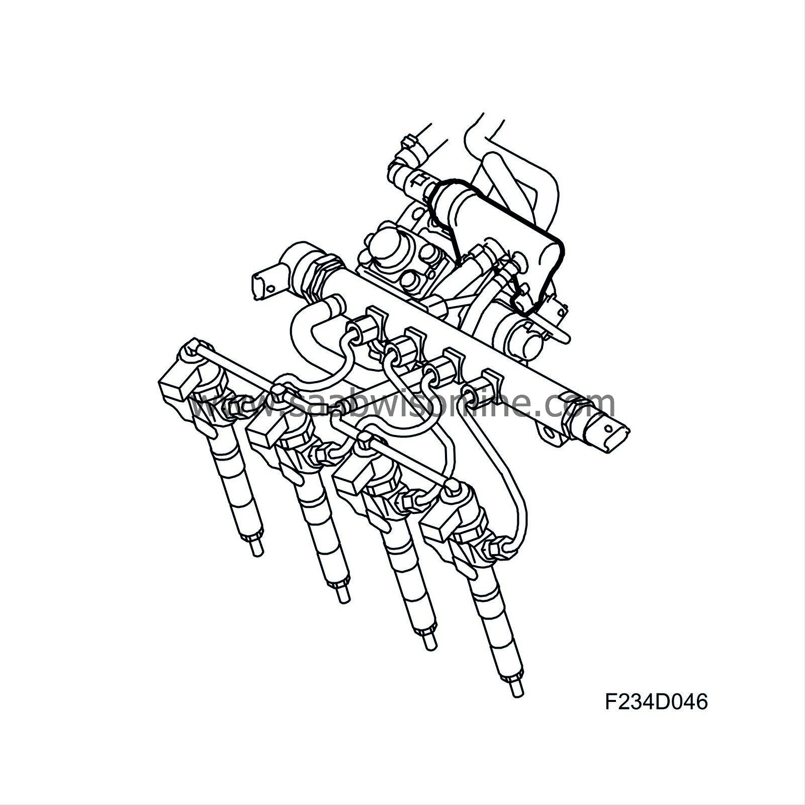
| Function description |
The fuel tank, which has a capacity of 58 litres, houses a fuel pump unit consisting of a feed pump (323) that forces fuel to the high pressure pump as well as a fuel level sensor (46), which is connected to ECM (595).
The feed pump is mounted in a reservoir from which it takes fuel. The reservoir is filled with fuel via an ejector pump driven by the return fuel flow. The purpose of such is to ensure that the reservoir is always full so that the feed pump does not take in air during significant heeling or the like.
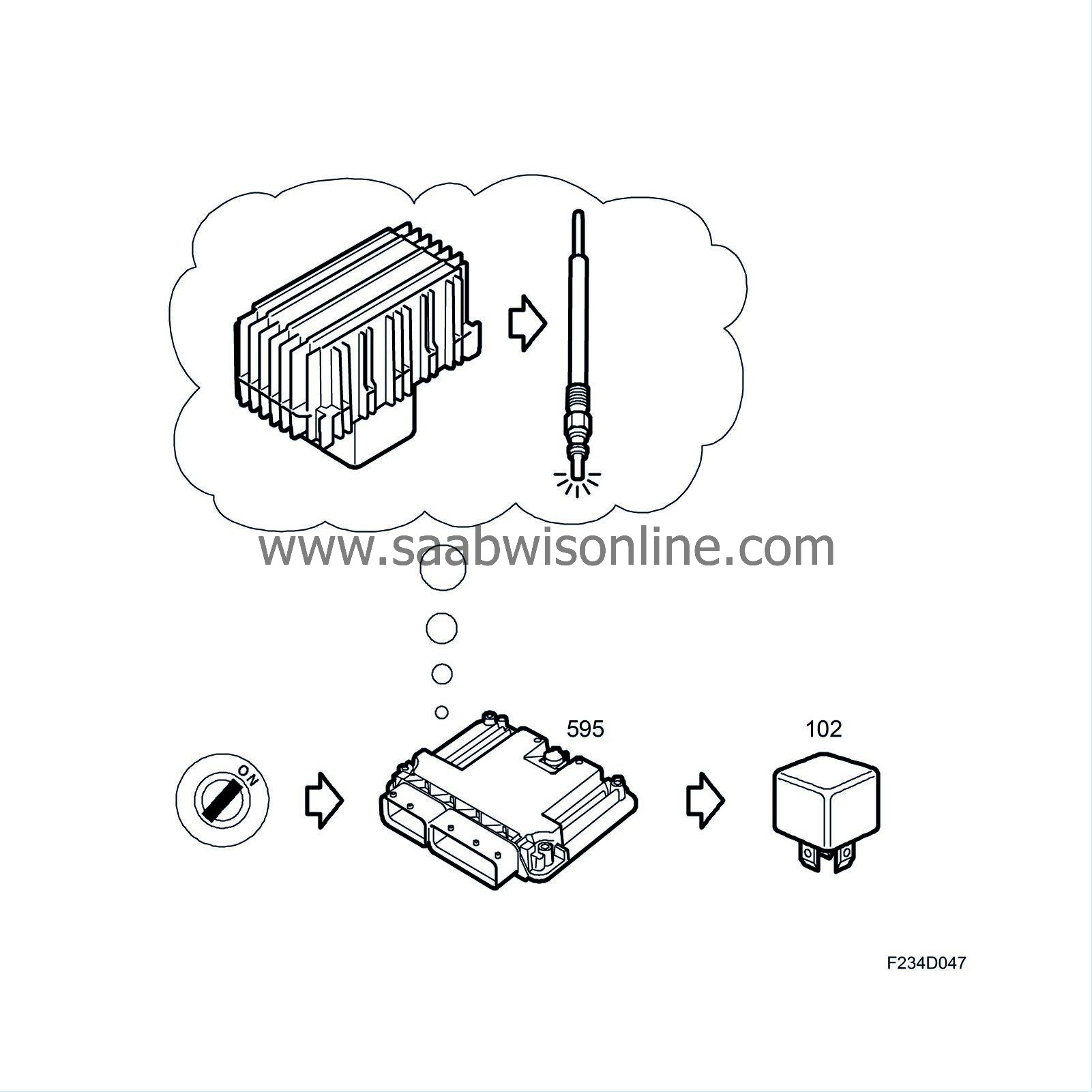
When the key is turned to the ON position, ECM activates the fuel pump relay (102) during any preheating period plus an additional 15 seconds to build up fuel pressure. After this time, the fuel pump stops and ECM activates the relay when the crankshaft begins to rotate. Fuel with a pressure of about 4 bar is now supplied via the fuel line to the fuel filter, where it is filtered and any water is separated. If necessary, ECM heats the fuel.
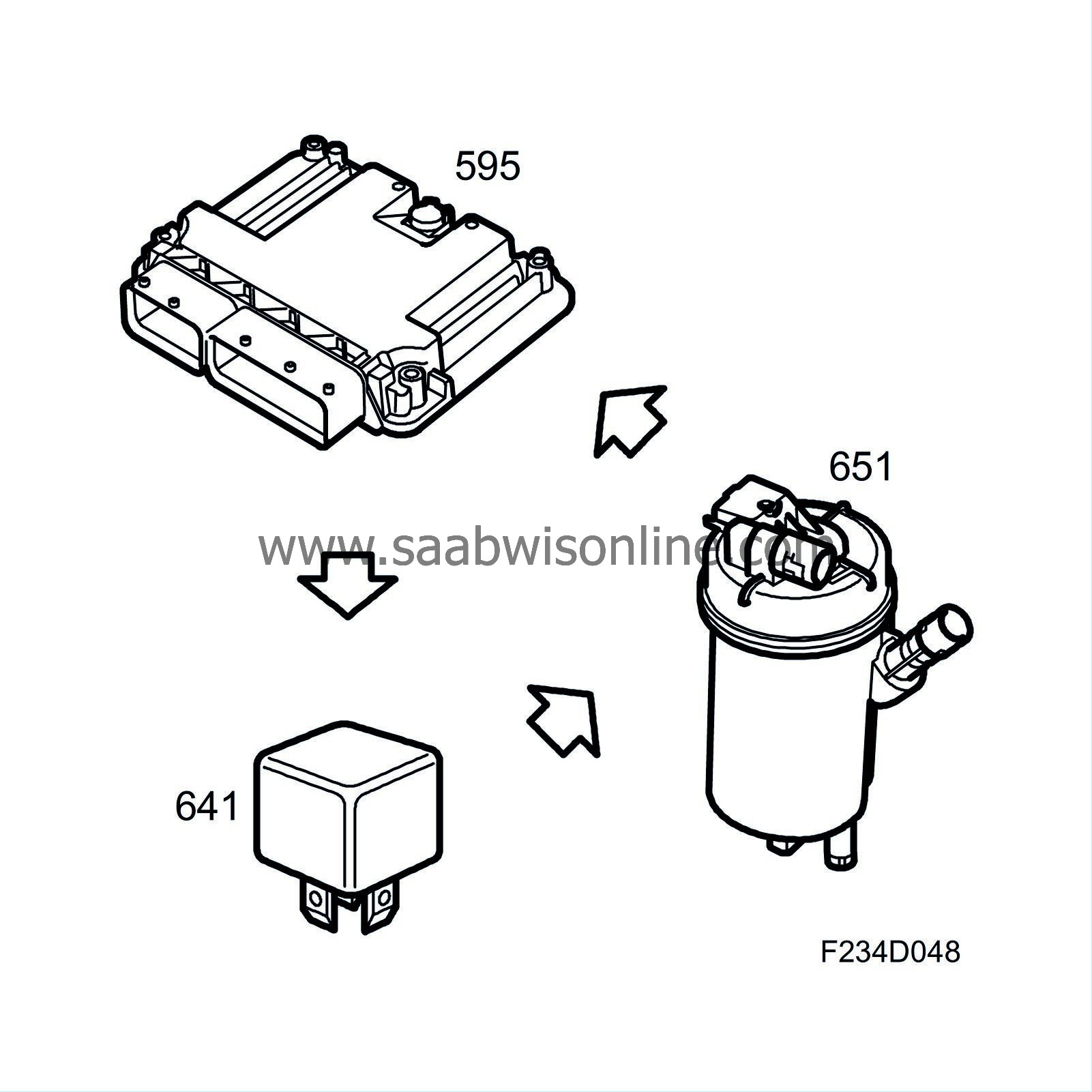
ECM gauges the temperature via the fuel temperature sensor (651). A preheating element within the fuel filter is supplied power via the preheating relay (641). ECM activates the preheating relay as necessary. If the filter is full of water and must be drained, the driver is warned of such via a message in the main instrument unit: Water in fuel. Contact workshop.
Fuel is led from the fuel filter on to the high pressure pump. The entrance to the high pressure has a fuel control valve (652b) which regulates the degree of fullness of the high pressure pump's pump element. The fuel control valve (652b) is regulated by ECM via PWM voltage. As the engine's fuel need changes over a large range, the fuel pressure delivered to the fuel rail by the high pressure pump must be regulated. This is done by the fuel control valve (652b) and the fuel pressure control valve (652a). It is measured by the fuel pressure sensor (653).
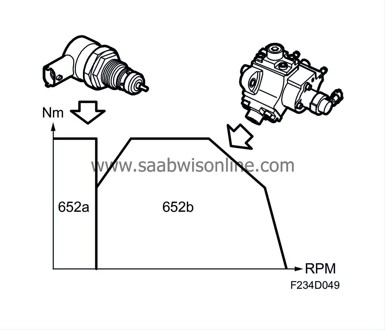
When the engine is started, the high pressure pump is allowed to deliver as much fuel as possible to obtain a quick and sure start. The fuel control valve (652b) is fully open at that time and fuel pressure is regulated by the fuel pressure control valve (652a).
When the engine is running at a speed above idling speed, fuel pressure is regulated by both the fuel control valve (652b) and the fuel pressure control valve (652a). Allowing both valves to work prevents pulsations caused by an uneven fullness degree of the high pressure pump's pump element. The pump works with a relatively high degree of fullness and the fuel pressure control valve (652a) is allowed to dump fuel so as to attain the correct fuel pressure.
At even higher engine speed, fuel pressure is regulated via the fuel control valve (652b). By not letting the pump run with a full degree of fullness, the torque need of the high pressure pump is reduced. This reduced torque need generates lower fuel consumption in the engine as it subjected to less of a load. During rapid needs of pressure reductions, the fuel pressure control valve (652a) dumps fuel to quickly lower the pressure. Depending on operating conditions, fuel pressure can reach 160 Mpa (1600 bar).
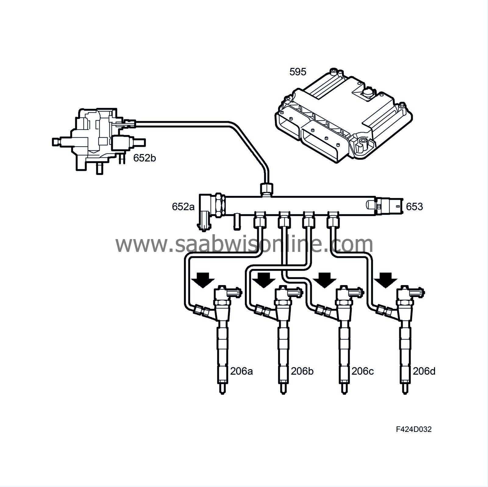
Fuel from the high pressure pump is led via a steel pipe to the fuel rail, which is made of steel and has a volume of 20 cm 3 . The volume, shape and location of the connections have been thoroughly tested to prevent disruptions in the form of fuel pressure pulsation, which would cause unequal distribution of fuel to the four nozzles.
Fuel is led from the fuel rail to the injectors via steel pipes. The length of these pipes is the same to prevent uneven fuel distribution.
The injectors are mounted in the cylinder head. Fuel is injected in the centre of the combustion chamber. The combination of seven holes in the nozzles, the centrally positioned injector and the shape of the combustion chamber generate a good blend of fuel in the air.
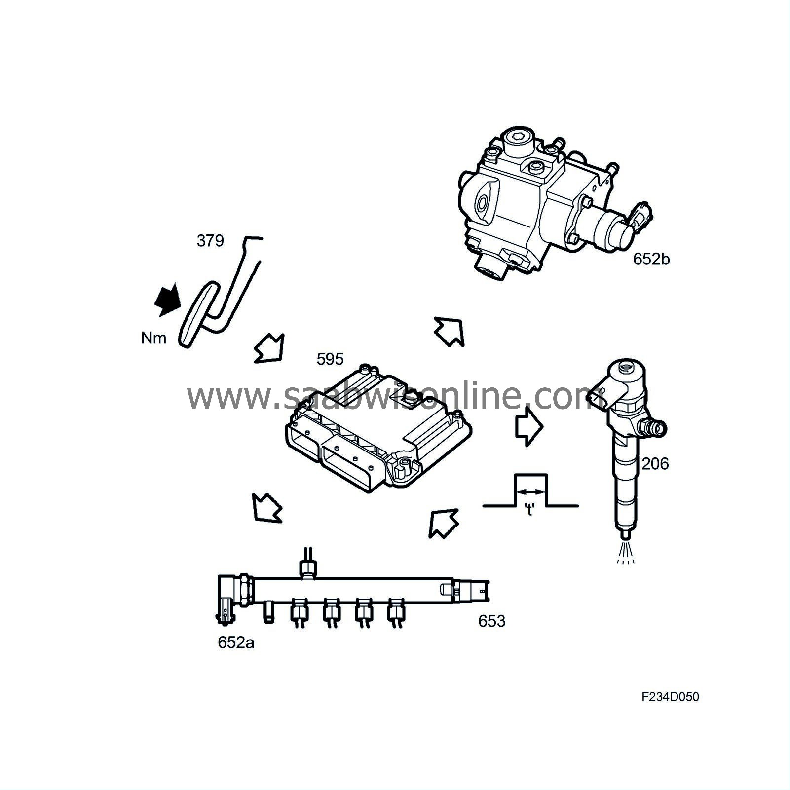
ECM regulates injector opening duration and the time point of opening (crankshaft position). The maximum opening duration is 1 ms. The injectors are directly regulated by ECM. The injected quantity is calculated by ECM with requested engine torque as the main parameter. The request comes from the accelerator pedal (379) or cruise control. A number of internal compensations are then added to or subtracted from the torque. The result is a total torque request that is converted to injection duration. At the same time, ECM calculates the air mass required for the fuel quantity in question so that the engine produces high output, low fuel consumption and low emissions. This request is sent to the turbo control. If the air mass is below the smoke limit, the injected fuel quantity is reduced until the air mass exceeds the smoke limit.


