Intake manifold/seal, Z19
| Intake manifold/seal, Z19 |
| To remove |
| Important | ||
|
Always use wing covers when working in the engine bay. |
||
| 1. |
Remove
High-pressure pump, Z19
.
|
|
| 2. |
Remove
EGR solenoid valve (606), Z19.
|
|||||||||
| 3. |
Loosen the coolant expansion tank cap to release any pressure.
|
|
| 4. |
Raise the car.
|
|
| 5. |
Remove the front spoiler shield.
|
|
| 6. |
Place a receptacle under the radiator and drain the coolant. Close the cock and fit the spoiler shield.
|
|
| 7. |
Lower the car to the floor.
|
|
| 8. |
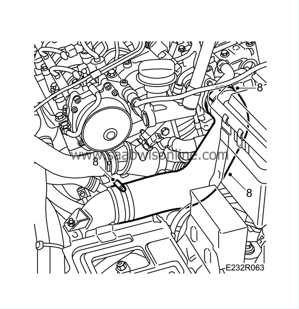
Detach the turbocharger delivery hose from the pipe and throttle body.
|
|
| 9. |
Place a receptacle under the engine to catch the coolant. Detach the coolant hose from the coolant pipe.

|
|
| 10. |
Detach the coolant hose from the thermostat housing.
|
|
| 11. |
Remove the nut holding the coolant pipe to the thermostat housing.
|
|
| 12. |
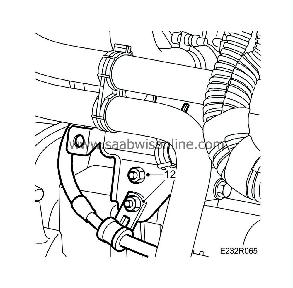
Remove the nuts holding the coolant pipes to the starter motor bracket. Move the pipes aside slightly to make room for the vacuum reservoir.
|
|
| 13. |
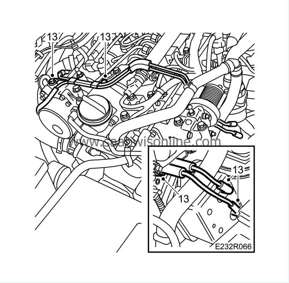
Detach the vacuum hoses from the vacuum reservoir. Remove the vacuum hose bolts from the camshaft housing and oil trap bracket.
|
|
| 14. |
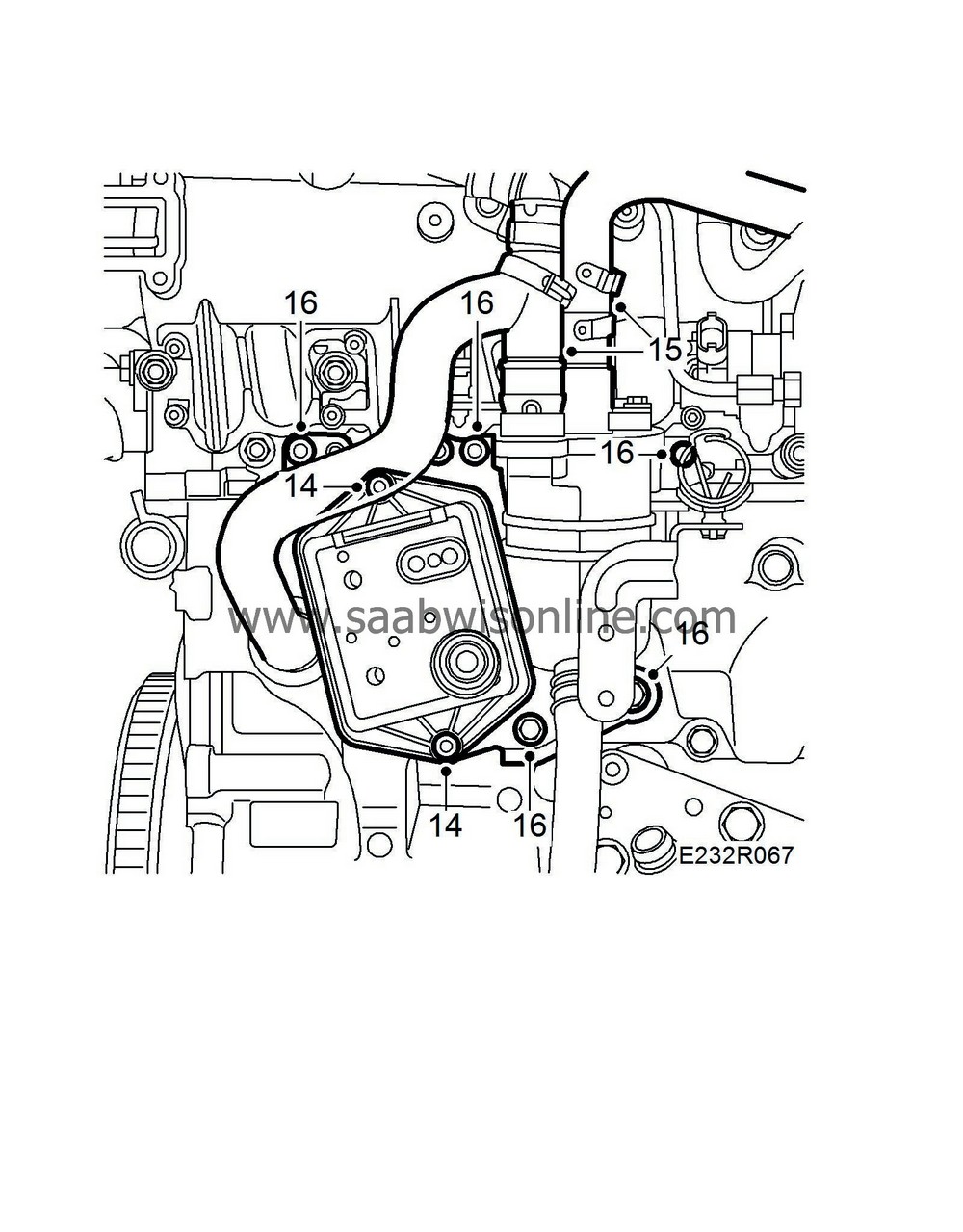
Remove the vacuum reservoir.
|
|
| 15. |
Detach the upper hoses of the oil trap. The right hose has a quick coupling to the oil trap.
|
|
| 16. |
Remove the nuts and bolts holding the oil trap bracket in place and move it aside.
|
|
| 17. |
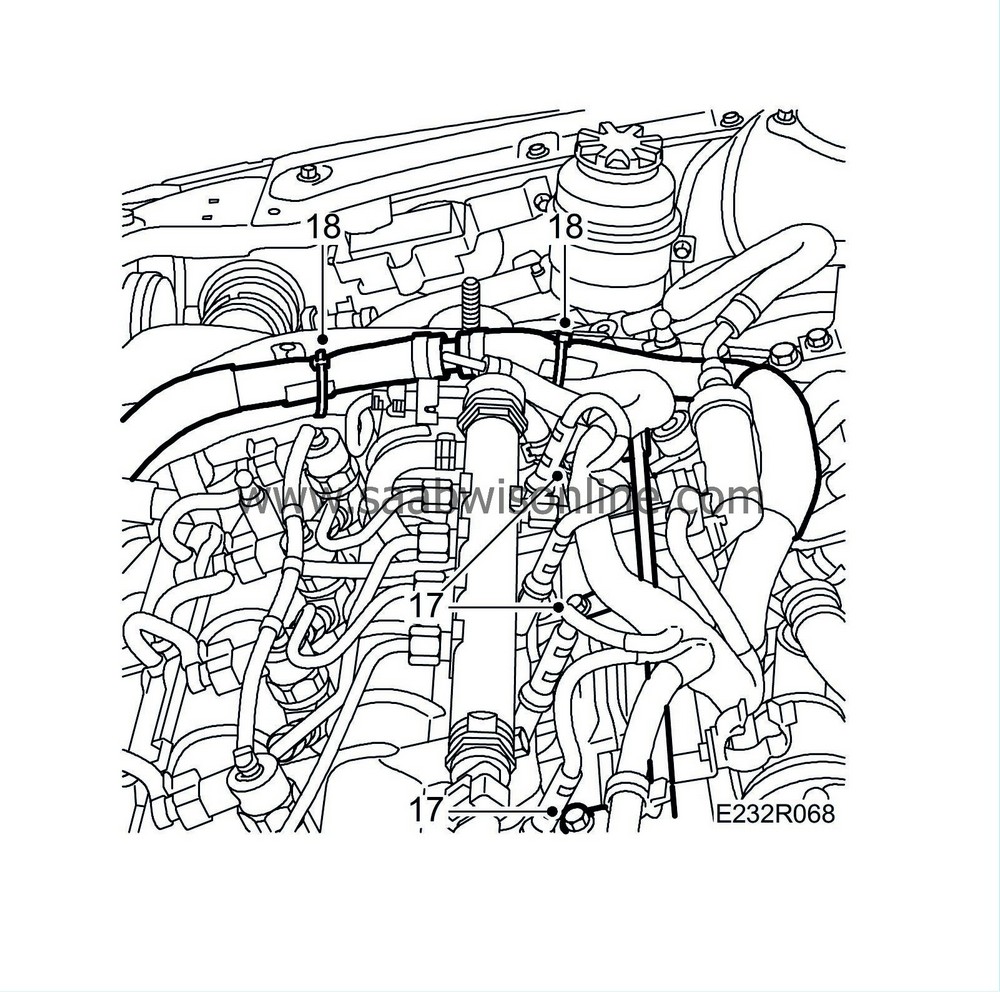
Undo the coolant line from the intake manifold.
|
|
| 18. |
Detach the wiring harness from the crankcase ventilation pipe. Remove the bolts holding the pipe in place and move it aside.
Cars with preheated crankcase ventilation : Cut the cable ties and remove the brackets.
|
||||||||||
| 19. |
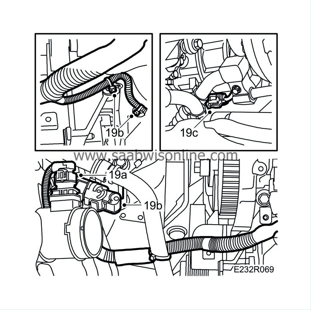
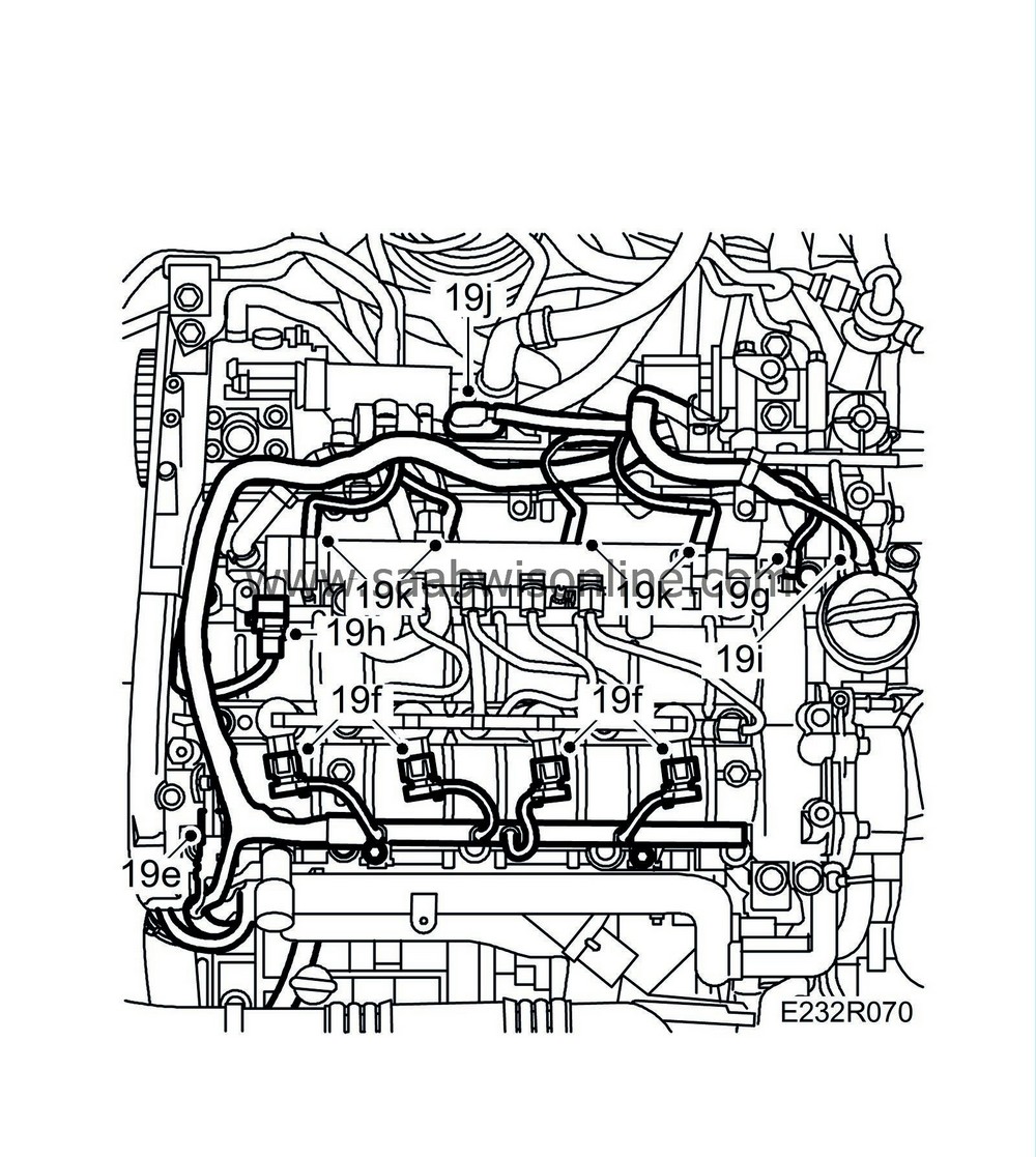
Unplug the following connectors:
|
|
| 19.a. |
Mass air flow sensor connector (686).
|
| 19.b. |
Wiring harness connector. Fit bracket and cable tie.
|
| 19.c. |
A/C compressor connector (170).
|
| 19.d. |
Front temperature sensor (602).
|
| 19.e. |
Camshaft position sensor (555).
|
| 19.f. |
Injectors (206).
|
| 19.g. |
Fuel pressure sensor (653).
|
| 19.h. |
Fuel pressure solenoid valve (652a).
|
| 19.i. |
Electronic throttle actuator (604).
|
| 19.j. |
Intake air sensor (688).
|
| 19.k. |
Glow plug connector (398).
|
| 20. |
Remove the retaining bolts of the cable duct and move the wiring harness aside.
|
|
| 21. |
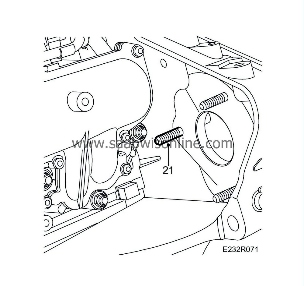
Remove the stud holding the high-pressure pump.
|
|
| 22. |
Unplug the connector of the combustion circulation actuator.
|
|
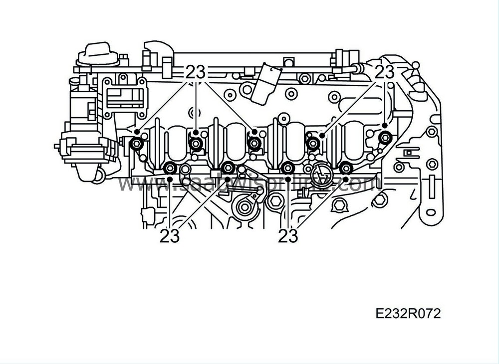
| 23. |
Remove the intake manifold.
|
|
| To fit |
| 1. |
Fit the intake manifold using a new seal.
Tightening torque 27 Nm (20 lbf ft) 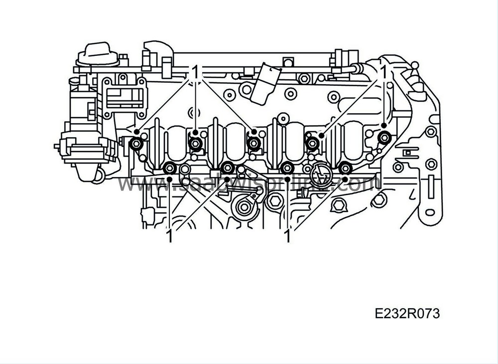
|
|
| 2. |
Plug in the connector of the combustion circulation actuator.
|
|
| 3. |
Fit the stud.

|
|
| 4. |
Attach the coolant pipe to the intake manifold.
|
||||||||||
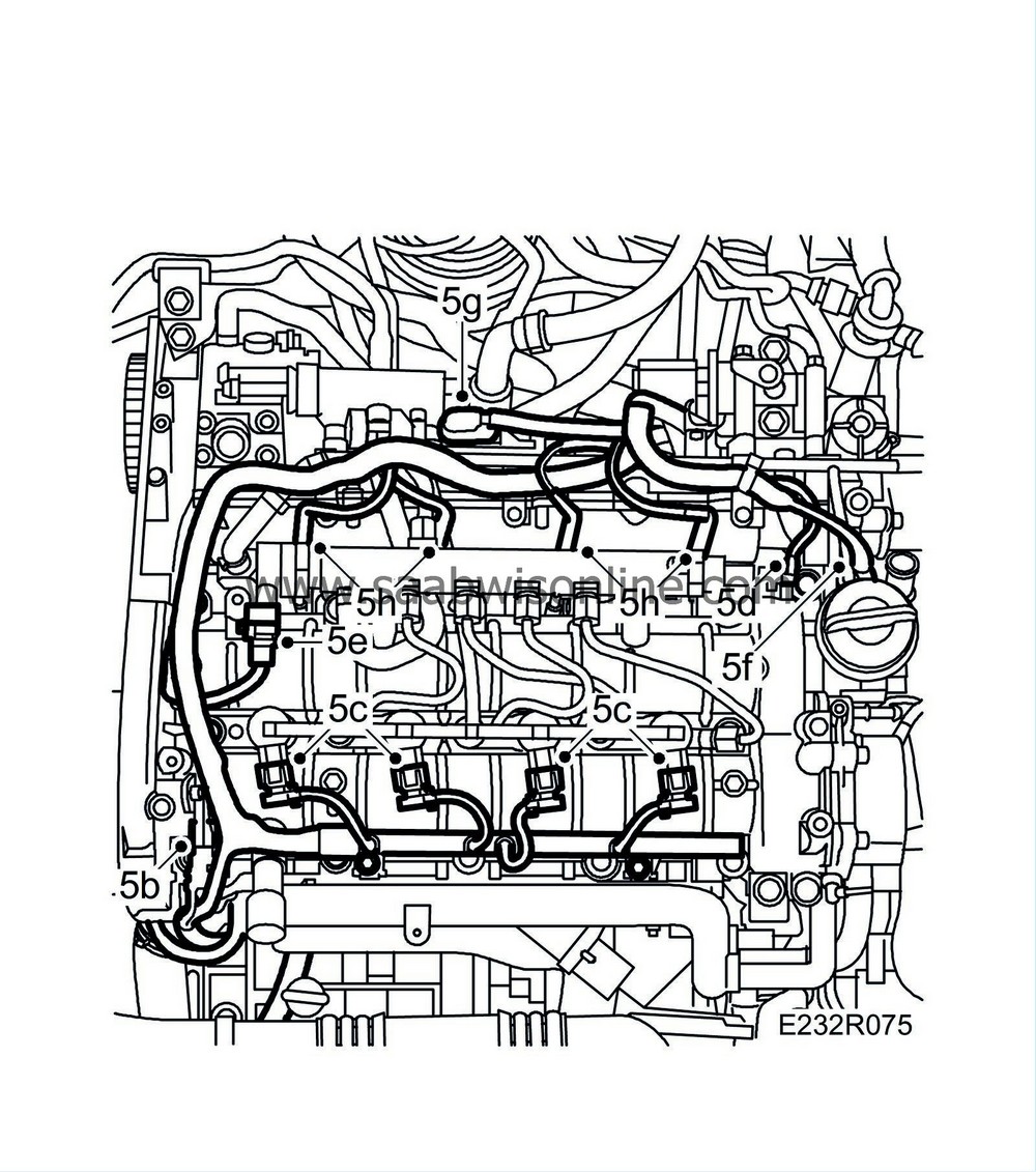
| 5. |
Fit the wiring harness and plug in the following connectors:
|
|
| 5.a. |
Front temperature sensor (602).
|
| 5.b. |
Camshaft position sensor (555)
|
| 5.c. |
Injectors (206).
|
| 5.d. |
Fuel pressure sensor (653).
|
| 5.e. |
Fuel pressure solenoid valve (652a).
|
| 5.f. |
Throttle body actuator (604)
|
| 5.g. |
Sensor, intake air (688)
|
| 5.h. |
Glow plug connector (398).
|
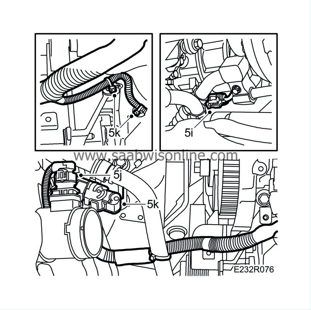
| 5.i. |
A/C compressor connector.
|
| 5.j. |
Mass air flow sensor connector. (686)
|
| 5.k. |
Wiring harness connector. Fit bracket and cable tie.
|
| 6. |
Cars with preheated crankcase ventilation
: Fit the brackets.
|
|
| 7. |
Fit the bolts holding the crankcase ventilation pipes in place. Fit the wiring harness.
Cars with preheated crankcase ventilation : Secure the wiring harness with cable ties. 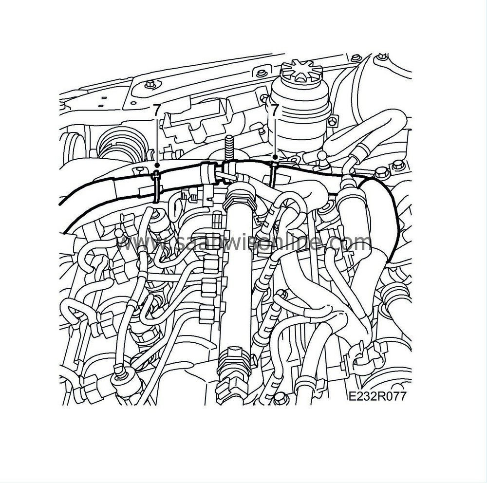
|
|
| 8. |
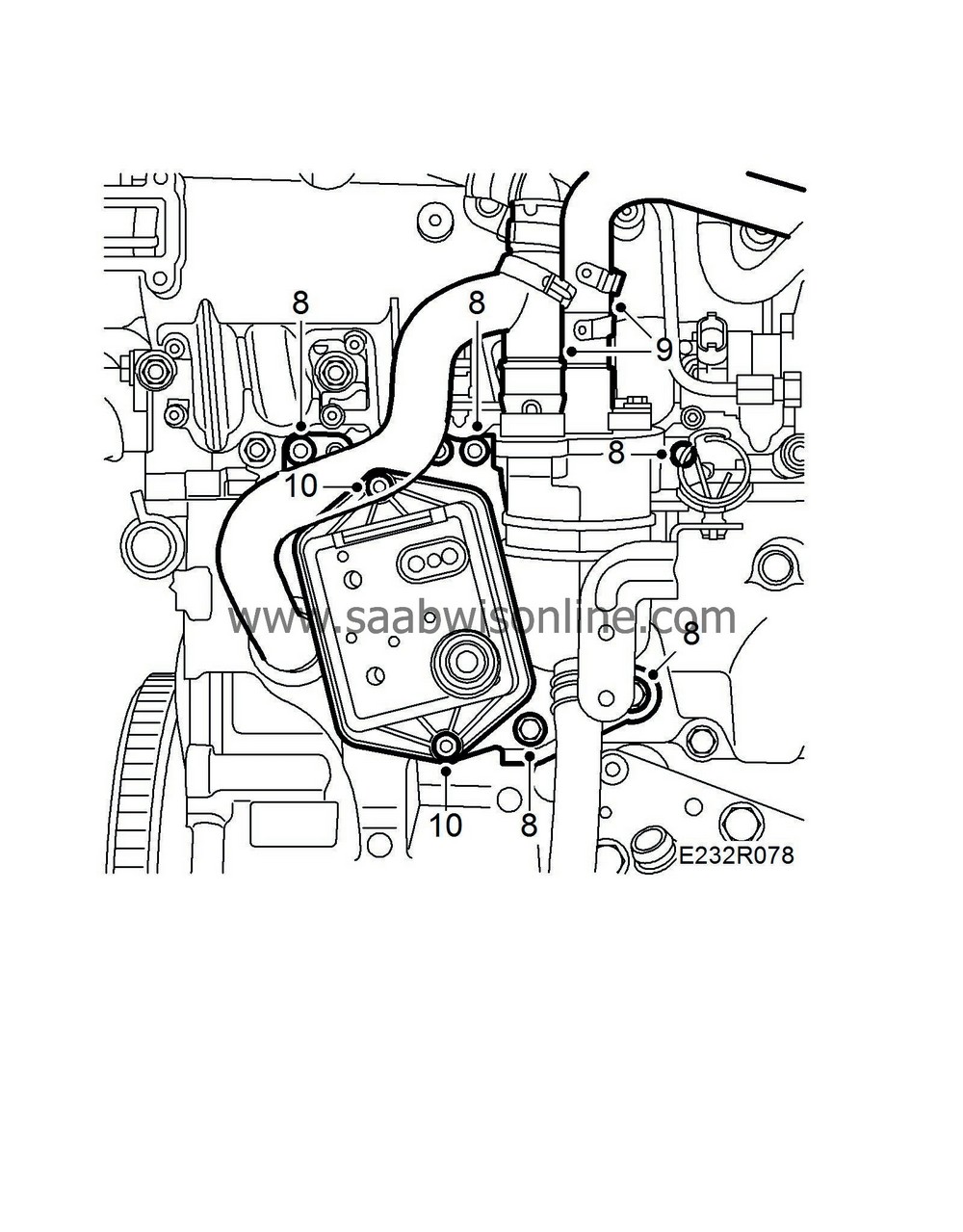
Reposition the oil trap bracket. Fit the nuts and bolts.
|
|
| 9. |
Attach the upper hoses of the oil trap.
|
|
| 10. |
Fit the vacuum reservoir.
|
|||||||
| 11. |
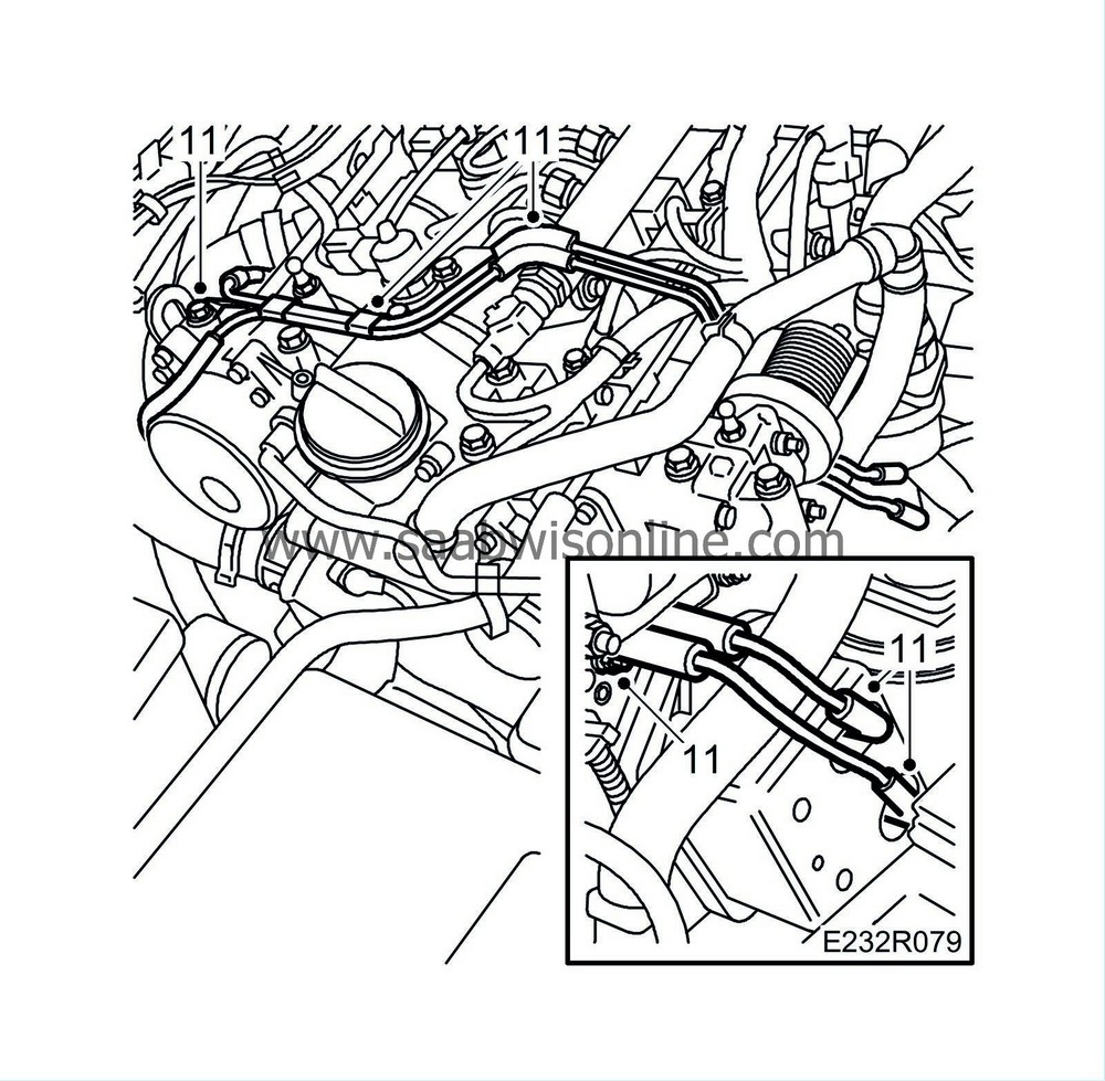
Attach the vacuum pipes to the camshaft housing and connect the hoses to the vacuum reservoir.
|
|
| 12. |
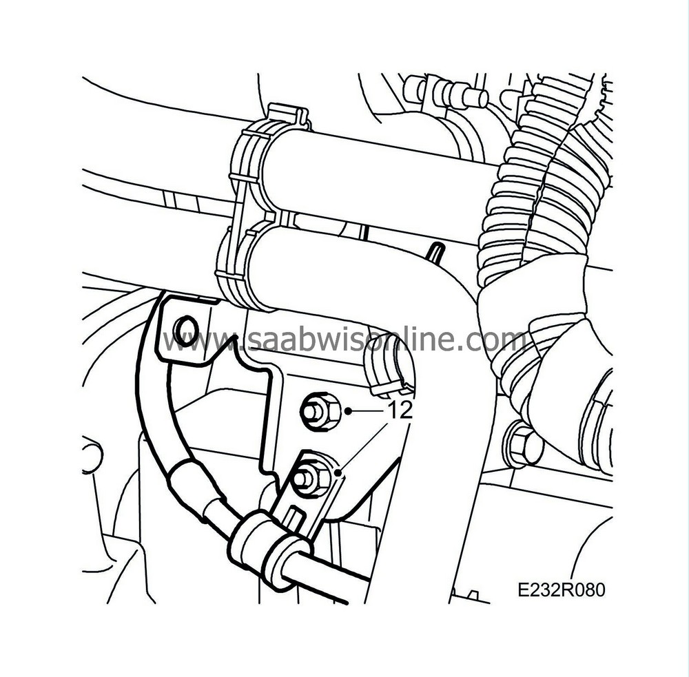
Fit the coolant pipes and wiring harness mounting to the starter motor bracket.
|
|
| 13. |
Secure the wiring harness on the brackets.
|
|
| 14. |
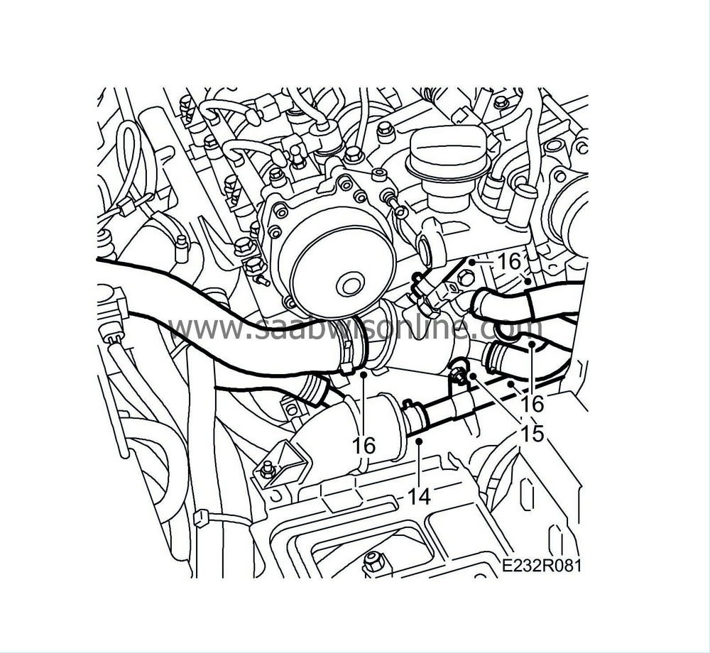
Attach the coolant hose to the coolant pipe.
|
|
| 15. |
Fit the nut holding the coolant pipe to the thermostat housing.
|
|
| 16. |
Attach the coolant hose to the thermostat housing.
|
||||||||||
| 17. |
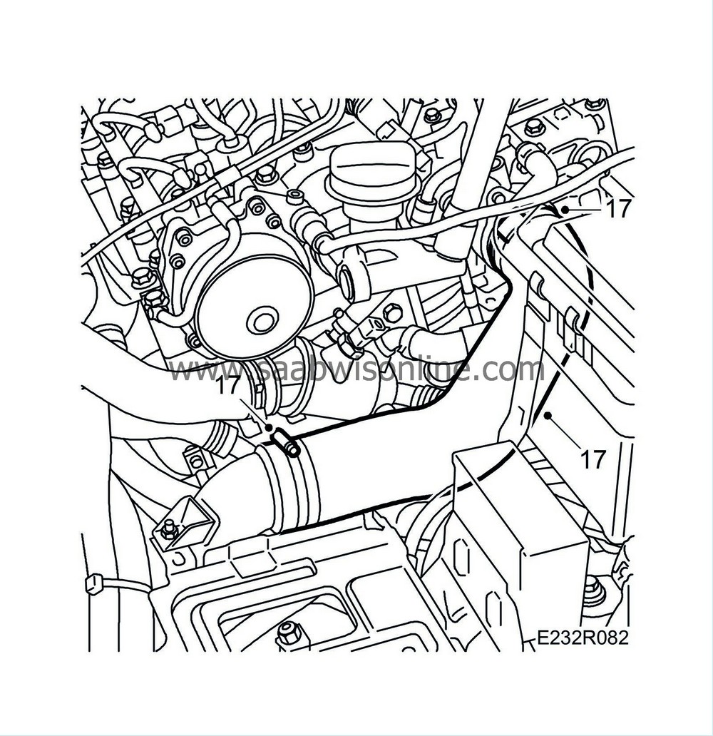
Attach the turbocharger delivery hose to the turbocharger delivery pipe and throttle body.
|
|
| 18. |
Attach the vacuum pipes to the camshaft housing and vacuum tank.
|
|
| 19. |
Fit
High-pressure pump, Z19
.
|
|
| 20. |
Fit
EGR solenoid valve (606), Z19.
|
|
| 21. |
Pressure test - see
Cooling system, pressure testing
- and fill coolant - see
Filling and bleeding cooling system
.
|
|
| 22. |
Connect an exhaust hose and start the engine. Check for leaks. Connect the diagnostic tool and clear any diagnostic trouble codes.
|
|

 Warning

