Diagnostic communication, bus-connected systems
| Diagnostic communication, bus-connected systems |

In order to communicate with all bus-connected control modules a CANdi box must be connected.
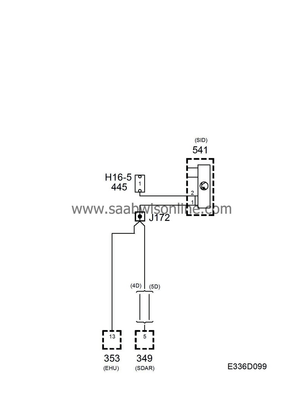
The diagnostic tool communicates directly with the connected control modules via the 1-lead I-bus. The EHU and SDAR control modules on the 1-lead I-bus are connected to pin 1 of the data link connector via an internal connection (between pins 1 and 2) in the SID control module.
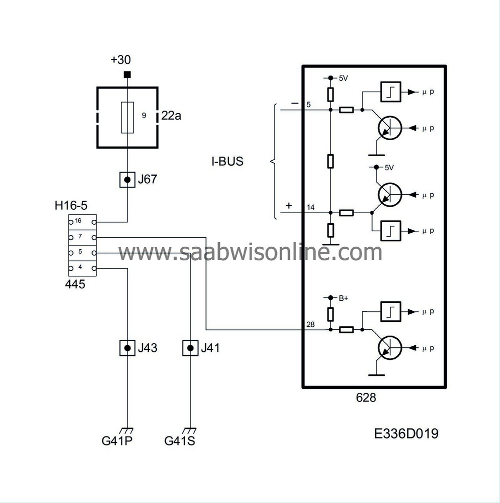
2DICE is connected with a communication lead to pin 7 of the data link connector. The diagnostic tool communicates digitally and serially with DICE. Digital means that the voltage difference between the lead and ground only has two values which in this case are approximately 0V and B+. Serial means that the information is sent in "packets" which are transmitted one after the other in rapid succession. Via contact with DICE, the diagnostic tool has access to all the control modules that are connected to the 2-lead P and I busses.
If, for example, the TCM is to be contacted, the diagnostic tool first calls up the DICE module and requests diagnostic communication with the TCM. The DICE module then transfers the request to the I-bus and from there the MIU relays the diagnostic request to the TCM via the P bus.
This means that both the DICE module and the MIU must be supplied with voltage (awake) in order to be able to contact the TCM.
Diagnosis
If none of the bus-connected systems can be contacted, the fault may be either in the car or the diagnostic tool. If the diagnostic tool can contact one of the systems concerned in another car, then the fault is in the car.For further information about finding faults relating to diagnostic communication with the DICE module or other bus-connected systems, see the following section ”Bus diagnosis”.


