(371-2621) Supplementary wiring harness for cruise control
Symptom: The cruise control does not work when retrofitted as accessory.
|
TECHNICAL SERVICE BULLETIN
|
|
Bulletin Nbr:
|
371-2621
|
|
Date:
...........
|
April 2006
|
|
Market:
|
ej US/CA
|
|
|
Supplementary wiring harness for cruise control
|
Saab 9-5 M06 without cruise control, where cruise control is to be retrofitted as an accessory.
The specification of the car does not include four cables to the cruise control, which must be retrofitted. From and including approx. W620 these cables will be pre-routed in the car. Following which, there will be no requirement for supplementary wiring harness for the cruise control.
In the case of customer complaint, the following action must be implemented.
Symptom description
The cruise control does not work when retrofitted as accessory.
3 x 0.35 mm
2
cables (grey/black, orange and grey). The length of each cable must be 1600 mm (
RHD:
2600 mm)
1 x 0.50 mm
2
brown cable at a length of 1000 mm
46 92 257 Cable terminal (x 6)
12 789 794 Cable terminal (x 1)
16-30 23 835 Cable terminal (x 1)
16-86 12 020 Crimp tool, available in tool kit 16-86 12 939
Extraction tool, available in tool kit 16-85 80 151
16-30 23 892 Seal (x 3), for cable terminals
79 71 872 Cable tie
LHD:
x 7,
RHD:
x 10
79 61 329 Bushing
93 160 907 Cleaning agent
91 96 462 Cavity sealant, Terotex HV 400 or Mercasol 1
Standox 1k Primer Filler
Finish coat, the colour code label is located on the inside of the glove box cover
Protective tape
|
1.
|
Prepare the wiring harness:
|
|
|
•
|
Tape the cables together (grey/black, orange and grey) with protective tape, approx. 1230 mm (
RHD:
2430 mm) long, starting 50 mm from one end.
|
|
|
•
|
Fit cable terminals 46 92 257 with seals 30 23 892 on the end where 50 mm loose cables were saved, use crimp tool 86 12 020.
|
|
|
•
|
Fit cable terminals 46 92 257 in the other end of the wiring, use crimp tool 86 12 020.
|
|
2.
|
Detach the battery's negative cable.
|
|
3.
|
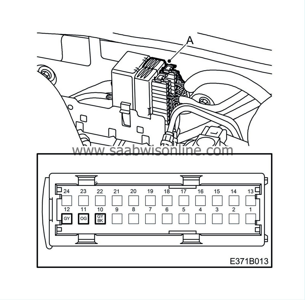
Plug the wiring harness into connector H24-1:
|
|
|
•
|
Remove the cover from the connector (A).
|
|
|
•
|
Unplug the inner connector (A).
|
|
|
•
|
Connect: the grey/black cable to pin 10, the orange cable to pin 11 and the grey cable to pin 12.
|
|
|
•
|
Plug in the connector (A).
|
|
4.
|
Remove the windscreen wipers and protective covers in accordance with WIS - Electrical System - Wash/wipe systems - Adjustment/Replacement - Windscreen wiper assembly (steps 1-4).
|
|
5.
|
LHD:
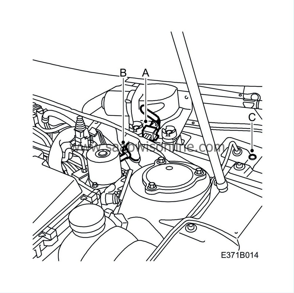
Route the wiring into the cabin:
|
|
|
•
|
Unplug the connector (A) from the wiper motor.
|
|
|
•
|
Remove the cable tie (B) from the bushing and detach the bushing. Route the wiring through and refit the bushing.
|
|
|
•
|
Remove the bushing (C). Drill a hole with an 8 mm bit through the insulation, where the bushing was fitted. Fit bushing 79 61 329 and route the wiring through.
|
|
|
•
|
Plug the connector (A) into the wiper motor.
|
|
6.
|
LHD:
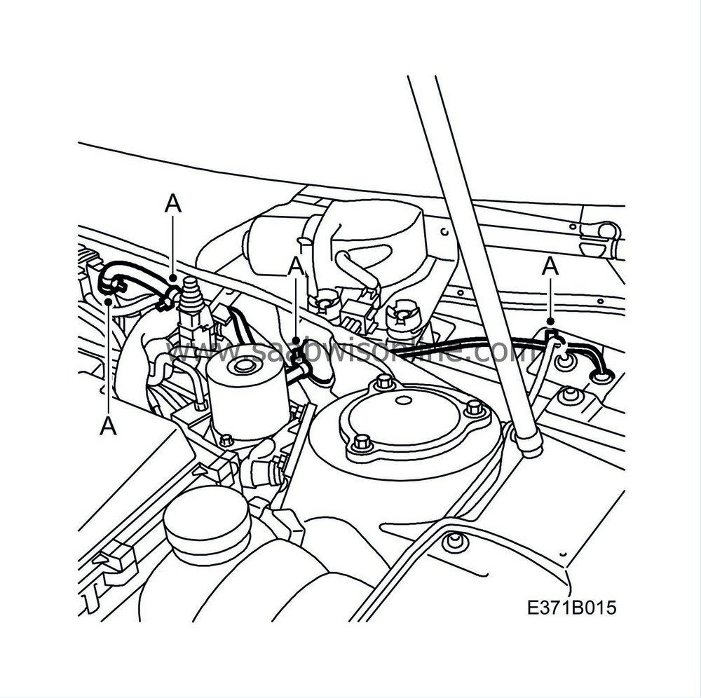
Secure the wiring with cable ties (A).
|
|
7.
|
RHD:
Remove the glove box in accordance with WIS - Body - Interior equipment - Adjustment/Replacement.
|
|
8.
|
RHD, cars with PMM:
Remove the control module (611) for rearview mirror memory.
|
|
9.
|
RHD:
Remove the ACC unit (216) in accordance with WIS - Body - Automatic Climate Control ACC - Adjustment/Replacement.
|
|
10.
|
RHD:
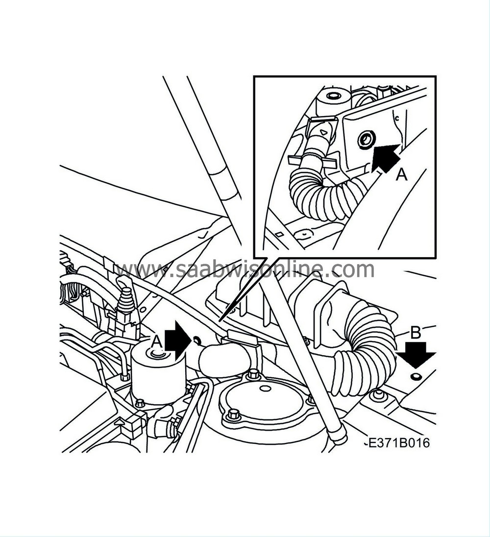
Route the wiring into the cabin:
|
|
|
•
|
Drill an 8 mm hole through the bushing and insulation (A), take care that the cable cluster is not damaged.
|
|
|
•
|
Route the wiring through.
|
|
|
•
|
Cut away the insulation around the raised part (B) and remove the bushing.
|
|
|
•
|
Drill an 8 mm through the insulation (B).
|
|
|
•
|
Remove loose swarf and paint flakes. Clean with Teroson Cleaning agent FL. Apply Standox 1K Primer Filler. Apply finish coat. Apply cavity sealant, Terotex HV 400 or Mercasol 1, on internal surfaces.
|
|
|
•
|
Fit the bushing 79 61 329 and route the wiring through.
|
|
11.
|
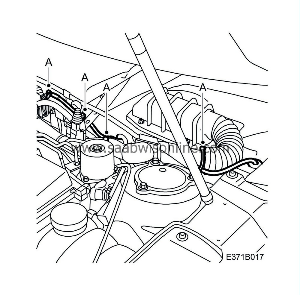
RHD:
Secure the wiring with cable ties (A).
|
|
12.
|
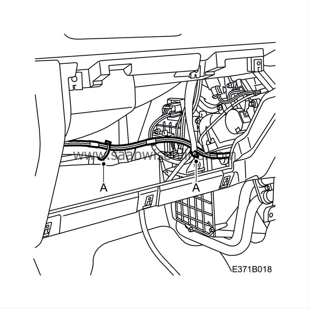
RHD:
Route the wiring through the centre console and secure with cable ties (A).
|
|
13.
|
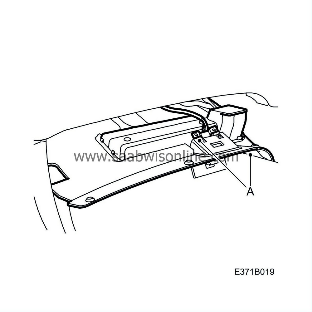
Remove the lower section of the dashboard (A) on the driver's side.
|
|
14.
|
Remove the steering column cover (A).
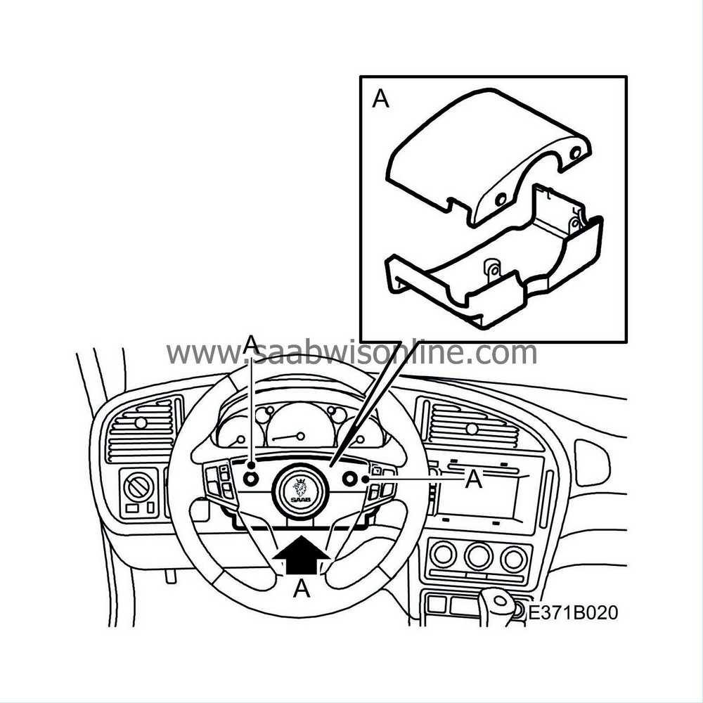
|
|
15.
|
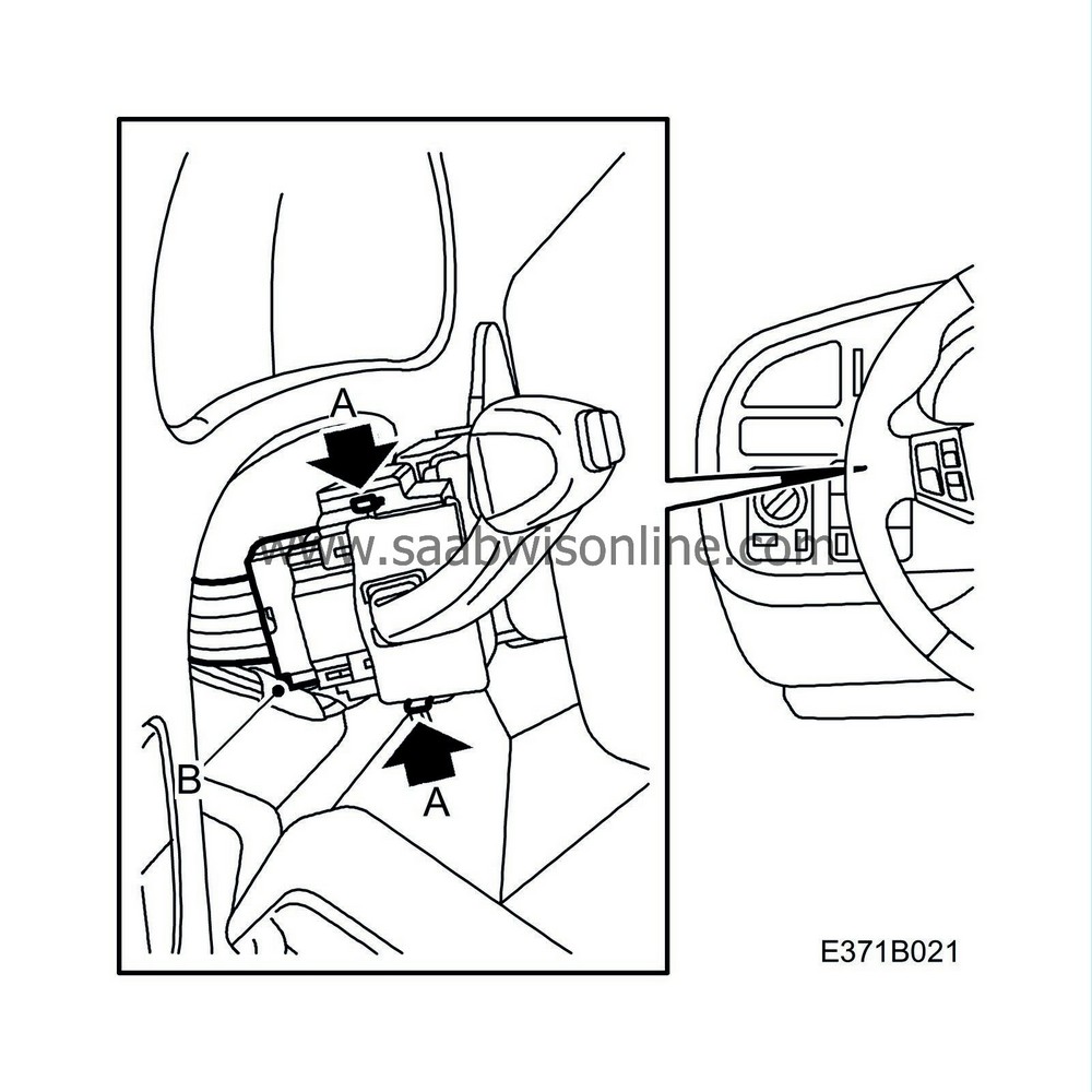
Remove the cruise control lever (A) and unplug connector (B).
|
|
16.
|
Route the wiring up, next to the steering column, through the grommet.
|
|
17.
|
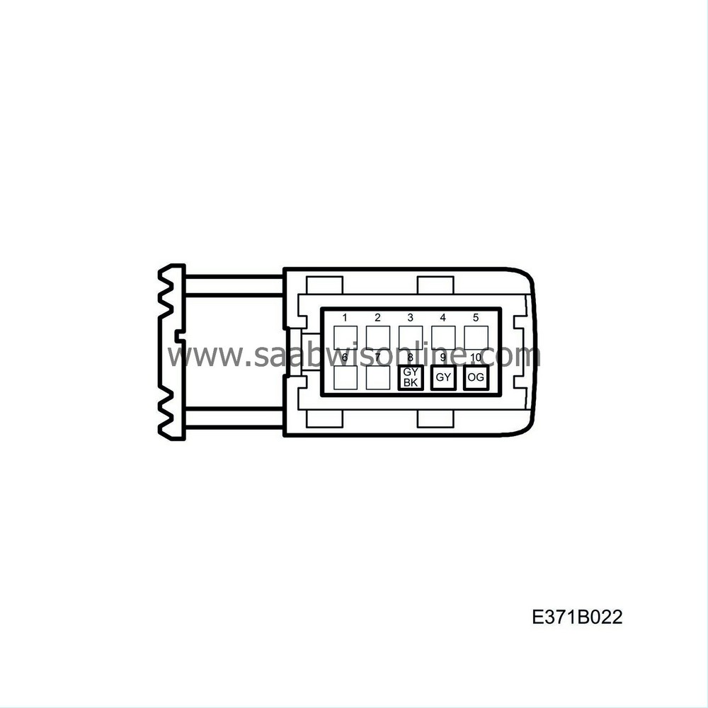
Connect: the grey/black cable to pin 8, the orange cable to pin 10 and the grey cable to pin 9 on the connector to the cruise control lever (141).
|
|
18.
|
Fit cable terminal 12 789 794 on one end of the brown cable, use crimp tool 86 12 020.
|
|
19.
|
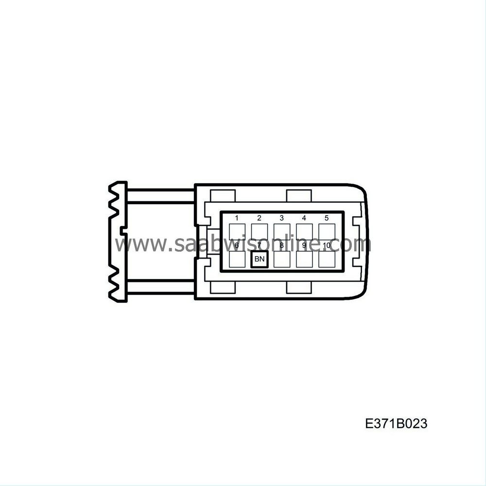
Connect the brown cable to pin 7 on the cruise control lever connector. Secure the wiring using cable ties approx. 50 mm from the connection.
|
|
20.
|
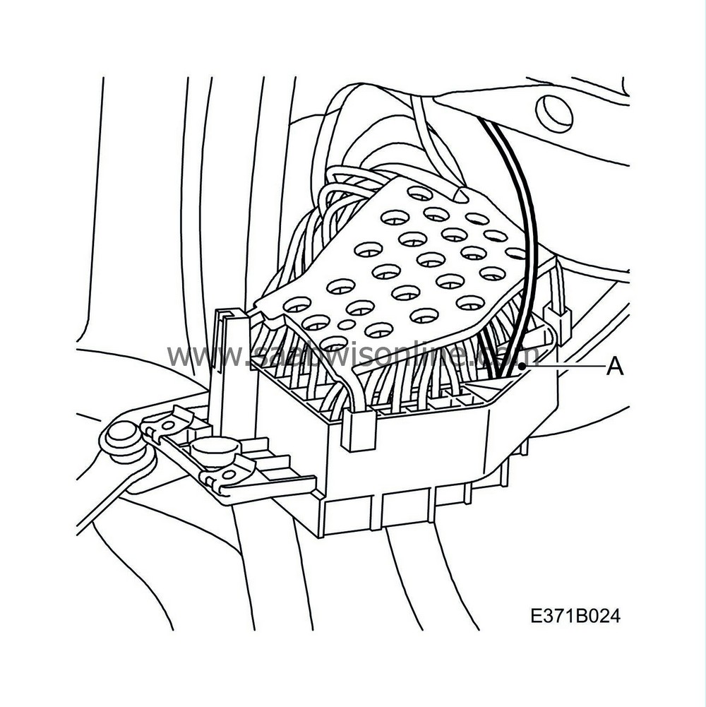
Connect the brown cable to the fuse box (22a):
|
|
|
•
|
Remove the cover to the fuse box on the end of the dashboard.
|
|
|
•
|
Remove the screws (x 3) securing the fuse box.
|
|
|
•
|
Remove connector pin (A) on the fused side of fuse 31 using removal tool 85 80 151.
|
|
|
•
|
Pair the brown cable on the fused side together with the existing cable to fuse 31, use sleeve 30 23 835.
|
|
|
•
|
Fit the fuse box and cover.
|
|
21.
|
Fit the cruise control lever (A) and plug in connector (B).

|
|
22.
|
Fit the steering column cover (A).

|
|
23.
|
Secure the wiring together with other wiring under the dashboard.
|
|
24.
|
Fit the lower section of the dashboard (A) on the driver's side.

|
|
25.
|
RHD:
Fit the ACC unit (216) in accordance with WIS - Body - Automatic Climate Control ACC - Adjustment/Replacement.
|
|
26.
|
RHD, cars with PMM:
Fit the control module (611) for rearview mirror memory.
|
|
27.
|
RHD:
Fit the glove box in accordance with WIS - Body - Interior equipment - Adjustment/Replacement.
|
|
28.
|
Fit the windscreen wipers and protective covers in accordance with WIS - Electrical system - Wash/wipe systems - Adjustment/Replacement - Windscreen wiper assembly (steps 4-6).
|
|
29.
|
Fit the cover to connector H24-1.
|
|
30.
|
Fit the battery's negative cable and carry out the procedures after battery disconnection in accordance with WIS - Electrical system - Adjustment/Replacement.
|
|
Warranty/Time Information
|


