|
No.
|
Name
Location
|
Illustration
|
|
|
Components
|
|
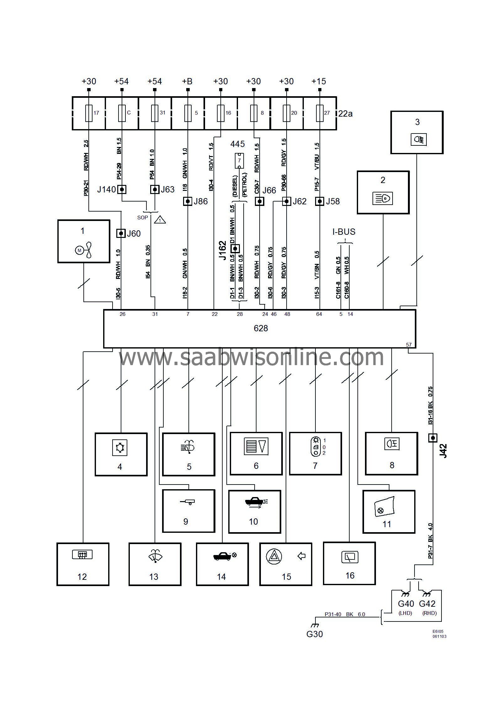
22a
|
Fuse box, dashboard
on end of dashboard next to driver's door
|

|
445
|
Data link connector, 16-pin CARB,
under dashboard by steering column
|

|
628
|
Control module, DICE,
LHD:
above the dashboard relay box
RHD:
behind the dashboard relay box
|

|
|
|
Crimp connectors
|
|
J42
|
LHD:
Approx. 145 mm from branching of grounding point G40 towards fuse box
RHD:
Approx. 50 mm from branching point of grounding point G42 towards relay box
|

|
J58
|
LHD:
Approx. 280 mm from branching of MIU/SID towards DICE control module
RHD:
Approx. 260 mm from rear edge of DICE control module connector towards engine bay
|

|
J60
|
LHD:
Approx. 40 mm from branching of DICE control module towards fuse box
RHD:
Approx. 240 mm from the rear edge of the DICE control module connector towards the engine bay
|

|
J62
|
LHD:
Approx. 155 mm from branching point of floor lighting (front left) towards DICE control module
RHD:
Approx. 50 mm from the branching point of the data link connector towards the steering wheel changeover switches.
|

|
J63
|
LHD:
Approx. 160 mm from branching DICE control module towards the fuse box
RHD:
Approx. 110 mm from branching data link connector towards DICE control module
|

|
J86
|
Approx. 40 mm from branching point of DICE control module towards fuse box
|

|
J140
|
LHD:
Approx. 120 mm from branching DICE control module towards fuse box
RHD:
Approx. 330 mm from branching of grounding point G42 towards DICE control module
|

|
J162
|
LHD:
Approx. 40 mm from branching DICE control module towards control module
RHD:
Approx. 80 mm from rear of DICE control module connector
|

|
|
|
Grounding points
|
|
G30
|
In engine bay on side plate in front of LH wheel housing.
|

|
G40
|
In cabin on LH side of knee member
|

|
G42
|
In cabin on RH side of knee member
|

|


