Brake servo
| Brake servo |
| 1. |
Outer air passage
|
|
| 2. |
Vacuum passage
|
|
| 3. |
Operating chamber
|
|
| 4. |
Vacuum chamber
|
|
| 5. |
Operating piston
|
|
| 6. |
Compression spring
|
|
| 7. |
Pushrod
|
|
| 8. |
Non-return valve
|
|
| 9. |
Valve
|
|
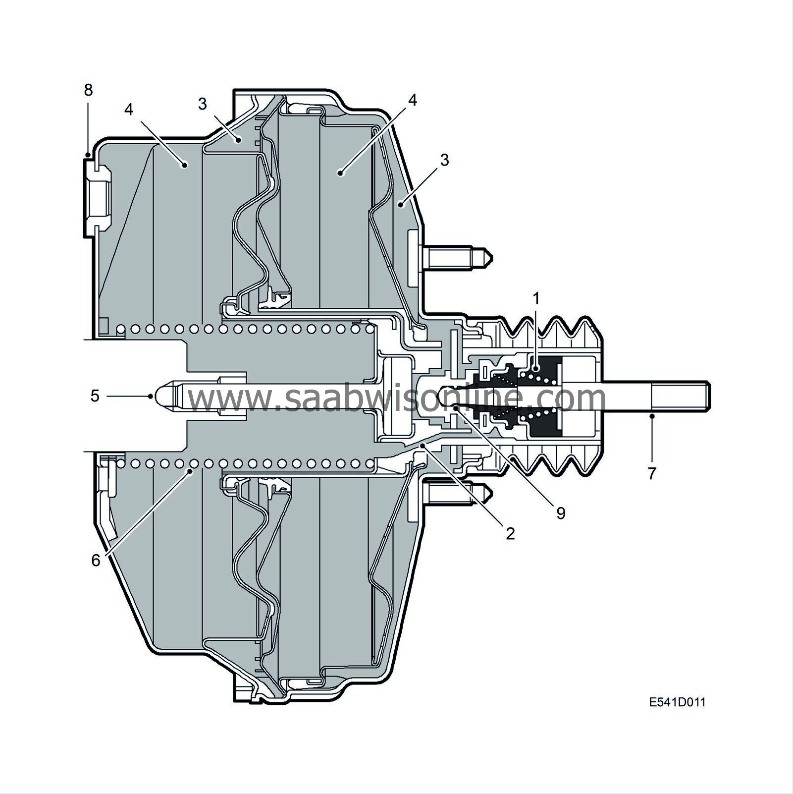
The brake servo unit boosts the pressure on the brake pedal exerted by the driver when the brakes are applied. The extra power supplied by the servo unit is obtained from the vacuum formed in the engine intake manifold or vacuum pump and provides assistance in the ratio of about 5.0:1. To achieve this servo assistance in a compact design, the servo unit has dual operating chambers.
The servo unit is connected to the intake manifold and the vacuum pump (certain variants) by means of a hose.
The servo unit consists of a metal casing, valve unit and dual diaphragm mounted between the brake pedal and master cylinder and connected to them by pushrods. If the supply of vacuum to the servo unit fails, the two pushrods act as a single pushrod. The brakes will then work conventionally without servo assistance but much greater pedal force will be required.
| Rest (brakes off) position |

| 1. |
Outer air passage
|
|
| 2. |
Vacuum passage
|
|
| 3. |
Operating chamber
|
|
| 4. |
Vacuum chamber
|
|
| 5. |
Operating piston
|
|
| 6. |
Compression spring
|
|
| 7. |
Pushrod
|
|
| 8. |
Non-return valve
|
|
| 9. |
Valve
|
|
In the rest (brakes off) position the outer air passage (1) is closed while the vacuum passage (2) is open. Equal vacuum is present in both the operating chambers (3) and the vacuum chambers (4). The operating piston (5) is kept in its right-hand rest position by the compression spring (6)
| Brakes partially applied |

| 1. |
Outer air passage
|
|
| 2. |
Vacuum passage
|
|
| 3. |
Operating chamber
|
|
| 4. |
Vacuum chamber
|
|
| 5. |
Operating piston
|
|
| 6. |
Compression spring
|
|
| 7. |
Pushrod
|
|
| 8. |
Non-return valve
|
|
| 9. |
Valve
|
|
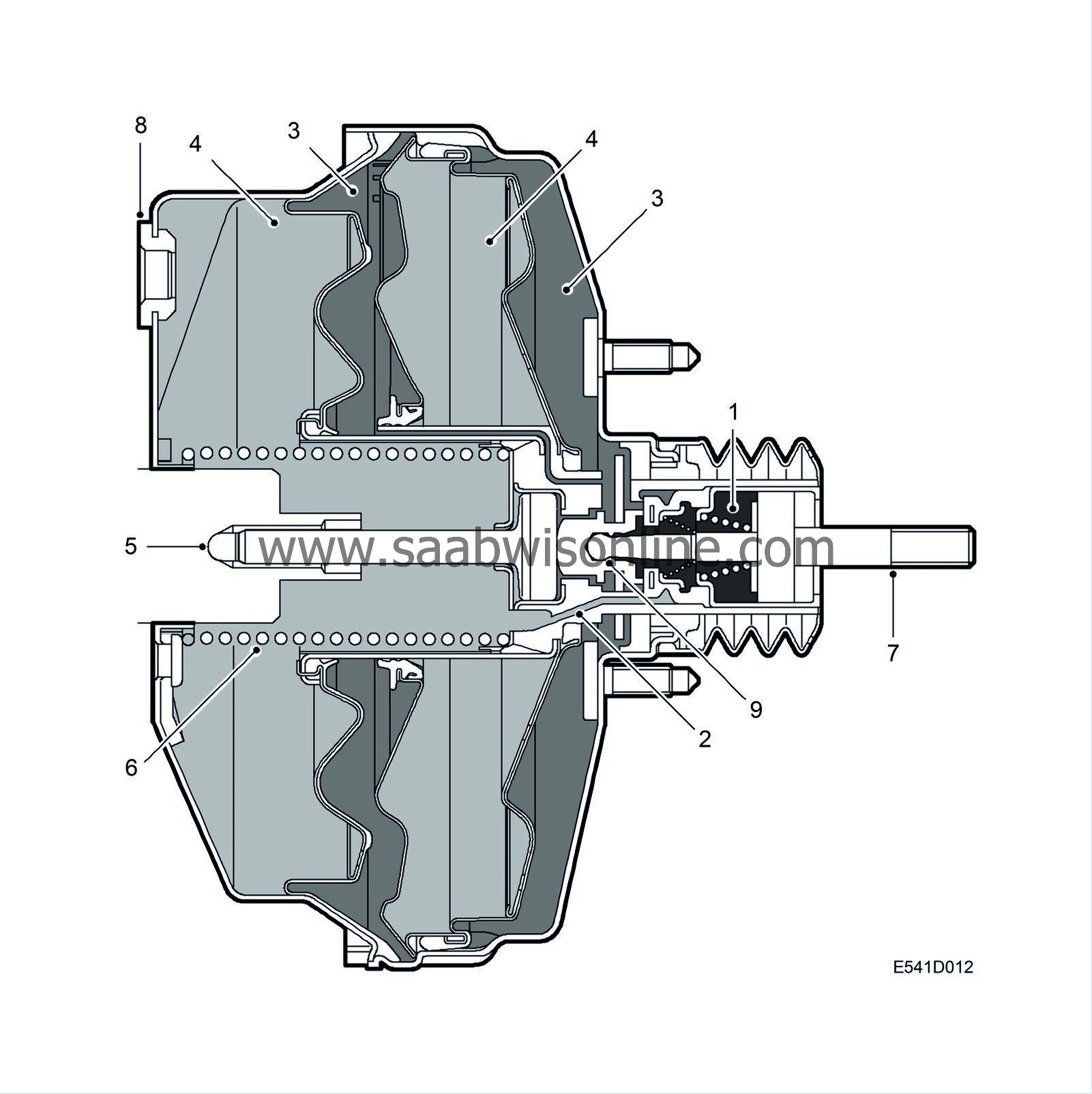
On depression of the brake pedal, the vacuum passage (2) is first closed and the outer air passage (1) opened. Air is then evacuated from the two vacuum chambers (4) while the two operating chambers (3) are filled with air at barometric pressure. The difference in pressure forces the two diaphragms to move in the same direction as the operating piston (5) and boosts the effort applied by the driver. When even pressure is applied to the brake pedal, the brake servo and master cylinder are in a state of equilibrium and the mechanism is stationary, the pressure increase in the operating chambers stops as the outer air passage closes. A state of readiness is now achieved where every pedal pressure change results in an increase or decrease of the pressure difference between vacuum chamber and operating chamber and so to an increase or decrease of braking power. A decrease in the pressure occurs when the brake pedal is released and the vacuum passage opens. Atmospheric air is then adm itted to the intake manifold until a state of equilibrium is again achieved and the vacuum passage closes.
| Brakes fully applied |

| 1. |
Outer air passage
|
|
| 2. |
Vacuum passage
|
|
| 3. |
Operating chamber
|
|
| 4. |
Vacuum chamber
|
|
| 5. |
Operating piston
|
|
| 6. |
Compression spring
|
|
| 7. |
Pushrod
|
|
| 8. |
Non-return valve
|
|
| 9. |
Valve
|
|
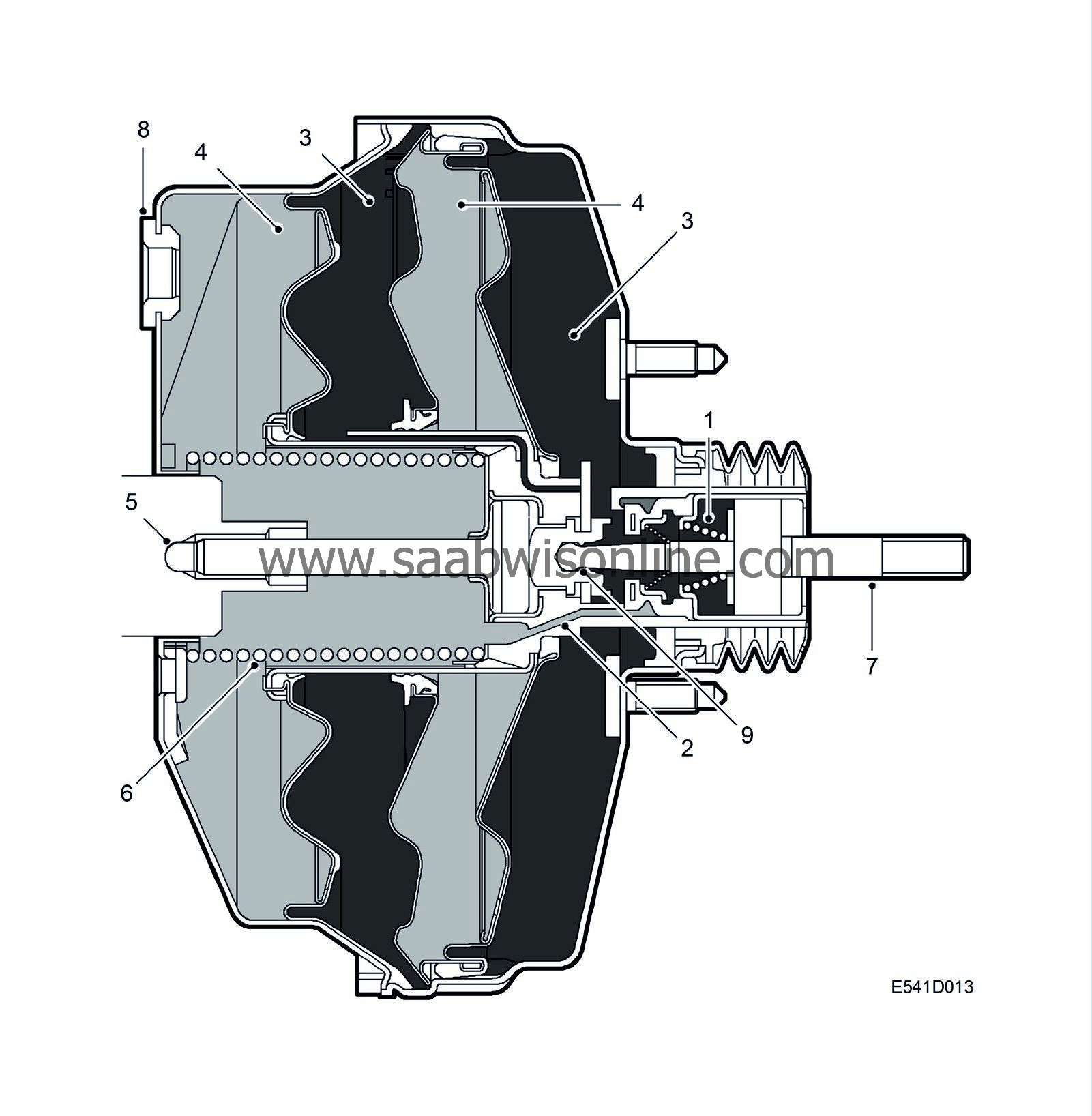
In the brakes fully applied position, the vacuum passage (2) is closed and the outer air passage (1) continuously open. The highest possible pressure difference then prevails between the chambers (3, 4) and with it the greatest possible brake servo assistance. Increasing the force on the master cylinder is possible only by increasing the force applied to the brake pedal.


