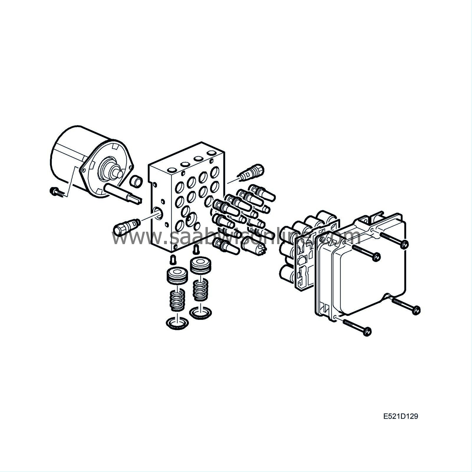
Valve block, function
| Valve block, function |
There is one inlet valve and one outlet valve per wheel. In standby, the inlet valve is open and the outlet valve is closed. During ABS operation, the inlet valve is closed to keep the pressure constant. The outlet valve opens when the return pump is started. The check valves parallel to the inlet valves even the pressure when the valve is active.
When the TCS function is activated, the pressure increase valve (closed when not active) and pressure relief valve (open when not active) for each front wheel are used. This means that one inlet and one outlet valve per wheel, and one pressure increase valve and one pressure relief valve per front wheel is used to lead the pressure to the spinning front wheel and transfer the power from the wheel with least grip to the wheel with best grip. There are 2 check valves for TCS in parallel with the pressure relief valves. If the driver brakes during TCS operation, the TCS function for braking will be switched off and the normal braking function selected. During the delay which may arise, the check valve mounted parallel with the pressure relief valve prevents the braking function from being affected by leading the brake pressure out to the wheel. The check valve mounted after the outlet valve prevents the accumulator from being filled with brake fluid. The pump is continuously active during TCS modulation.
TCS modulation is described under TCS modulation with braking .
The pressure increase and pressure relief valves are also connected to the rear wheel brakes to enable ESP control. The inlet and outlet valves are also activated during ESP modulation. This solution makes it possible to build up pressure, maintain pressure and reduce pressure individually on all four wheels.
If the driver applies the brakes while ESP regulation is active, the control module reads off the input brake pressure in the hydraulic unit. With this information, the brake pressure to the wheels not under ESP control can be controlled to correspond to the driver's braking force. The wheel under ESP modulation when the brakes are applied is controlled according to the ESP criteria.
See the description and illustrations under ESP regulation with brake application .
The pump runs continually during TCS and ESP operation.
The valve block incorporates an accumulator chamber and a pressure chamber for each brake circuit. The accumulator chamber, which is located between the outlet valve and the return pump, accumulates the brake fluid until the return pump starts.
Diagnostic help
The control module performs a valve test each time the ignition is switched on. This test takes place at the same time as the pump-motor test and the valves are actuated for 20 ms.
| 1. |
Front left pressure increase valve
|
|
| 2. |
Front right pressure increase valve
|
|
| 3. |
Pressure relief valve, front left
|
|
| 4. |
Front right pressure relief valve
|
|
| 5. |
Return pump
|
|
| 6. |
Brake caliper, front left
|
|
| 7. |
Brake caliper, front right
|
|
| 8. |
Brake caliper, rear left
|
|
| 9. |
Brake caliper, rear right
|
|
| 10. |
Front left inlet valve
|
|
| 11. |
Front right inlet valve
|
|
| 12. |
Rear left inlet valve
|
|
| 13. |
Rear right inlet valve
|
|
| 14. |
Front left outlet valve
|
|
| 15. |
Front right outlet valve
|
|
| 16. |
Rear left outlet valve
|
|
| 17. |
Rear right outlet valve
|
|
| 18. |
Accumulator chamber
|
|
| 19. |
Brake pressure sensor
|
|
| 20. |
Check valve
|
|
| 21. |
Check valve
|
|


