(850-2654) Fitting the passenger airbag
Symptom: There is no passenger airbag in the car.
|
MODIFICATION INSTRUCTION
|
|
Bulletin Nbr:
|
850-2654
|
|
Date:
...........
|
December 2006
|
|
Market:
|
Grekland
|
|
|
Fitting the passenger airbag
|
|
Customer Satisfaction Program 154 54
|
Cars in stock must be rectified before delivery.
A personal communication must be sent to the owners of cars already delivered requesting them to get in touch with the nearest Saab garage as soon as possible to have the fault rectified.
Saab 9-5 M06
Due to a specification error, cars have been built without the passenger airbag.
Symptom description
There is no passenger airbag in the car.
12 772 222 Electronic unit, ACM
12 757 093 Airbag, passenger
12 774 268 Dashboard
12 765 944 Wiring harness, airbag
11 900 439 Nut, (6 per car)
79 72 607 Screw
82 78 558 Protective moulding
79 71 864 Cable tie (20 per car)
54 65 596 Label
Thread locking adhesive, Loctite 242 (www.loctite.com)
Fabric tape
For fitting the modification identity plate:
12 785 148 Modification identity plate
93 160 907 Cleaning agent Motip Dupli, aerosol 400 ml (sufficient for 50-100 cars)
|
Checking the modification identity plate
|
Before proceeding, check box B2 of the modification identity plate. From and including M04 the car's Warranty and Service Book contains the "Table of Modifications". A modification identity plate must be fitted in accordance with the section "Fitting the modification identity plate" where local directives require the marking of the car. If the box is not marked, continue as follows.
|
|
•
|
Affix the new wiring harness adjacent to the existing cable ties wherever possible.
|
|
|
•
|
The old wiring must be cut away. This must be as close to the cable branching as possible and the end must be insulated.
|
|
|
•
|
Fabric tape must always be used for insulating the wiring.
|
|
|
•
|
If the car is equipped with a radio other than a Saab original radio then check whether or not the customer has the radio code before starting work.
|
|
2.
|
Remove the front passenger seat in accordance with WIS - Body - Seats - Front seat - Adjustment/Replacement.
|
|
3.
|
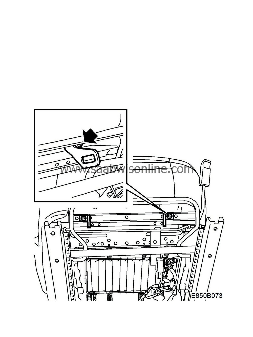
Remove the child seat mountings:
Power seat
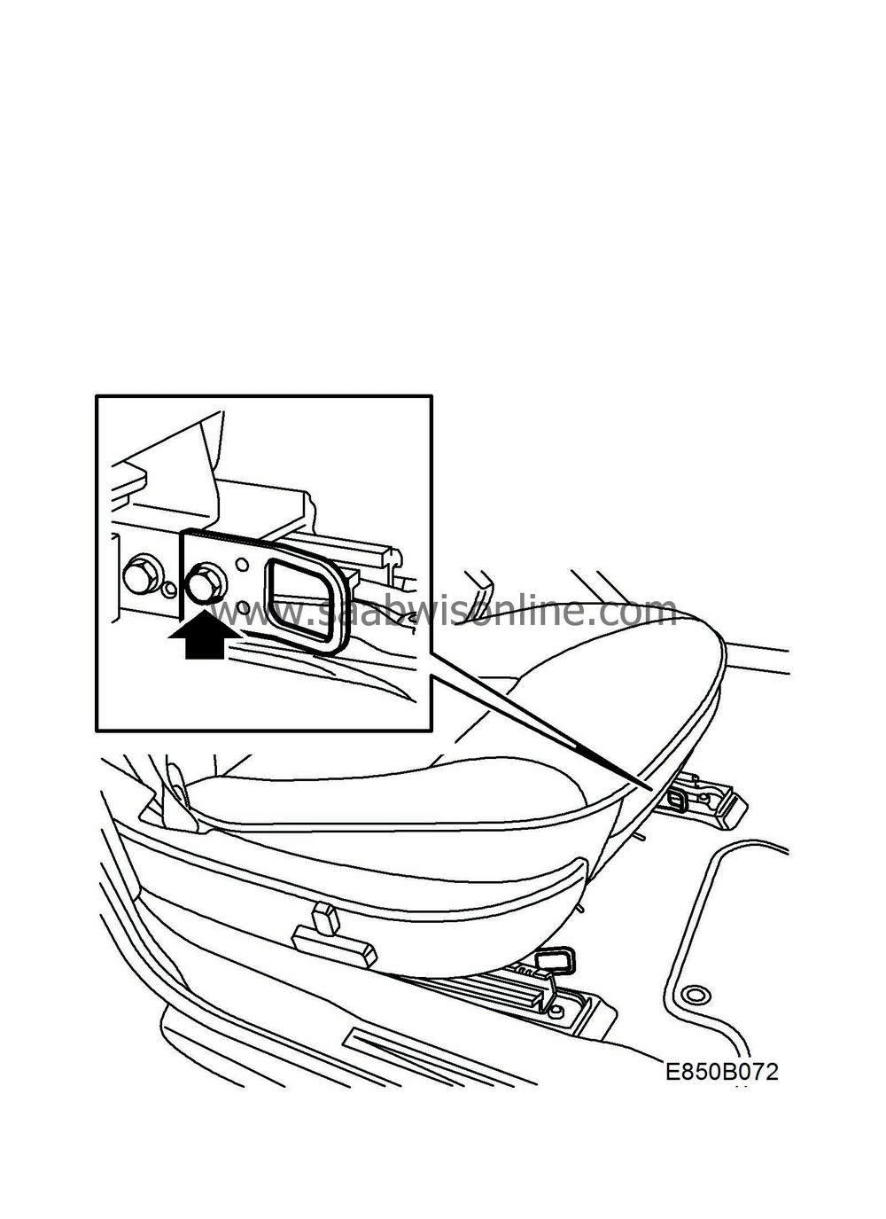
Manual seat
|
|
4.
|
Disconnect the battery's negative lead.
|
|
5.
|
Remove the dashboard in accordance with WIS - Body - Interior equipment - Adjustment/Replacement.
|
Note
|
|
Step 20 in the WIS instructions is not applicable as no passenger airbag is fitted.
|
|
|
6.
|
Transfer over the metal bracket, the air vents and the air duct from the old dashboard to the new one.
|
|
7.
|
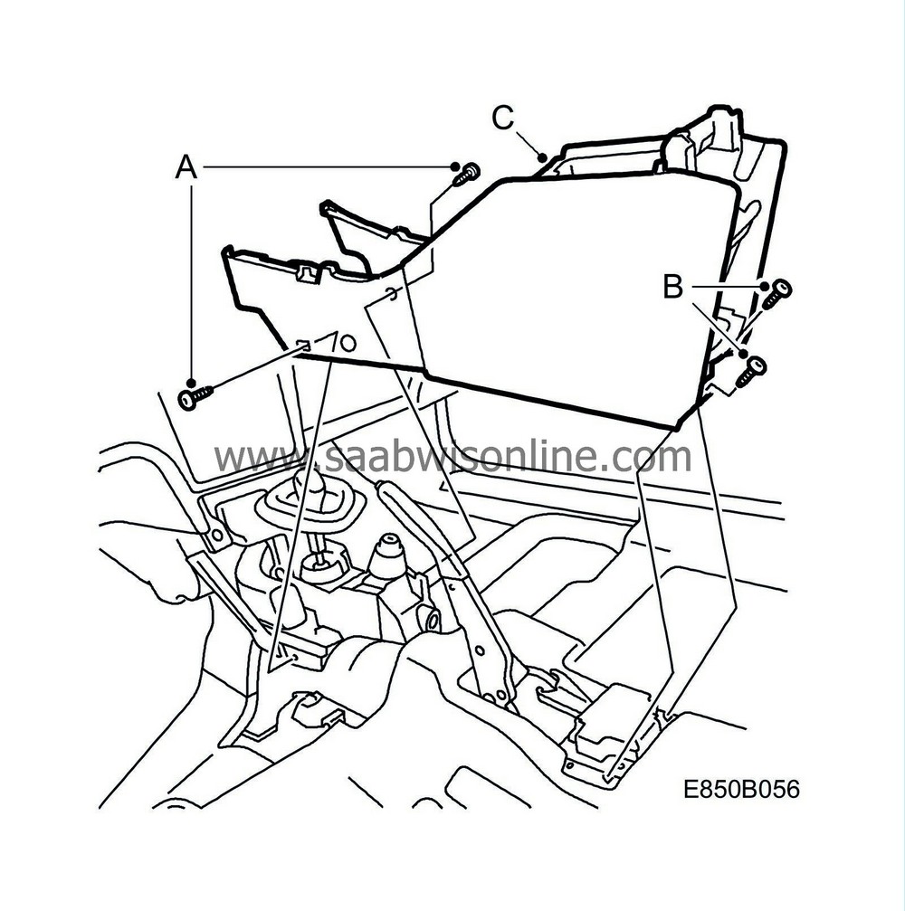
Remove the centre console:
|
|
|
•
|
Fold aside the front mats and undo the front screws (A).
|
|
|
•
|
Undo the rear screws (B).
|
|
|
•
|
Raise and remove the centre console (C).
|
|
8.
|
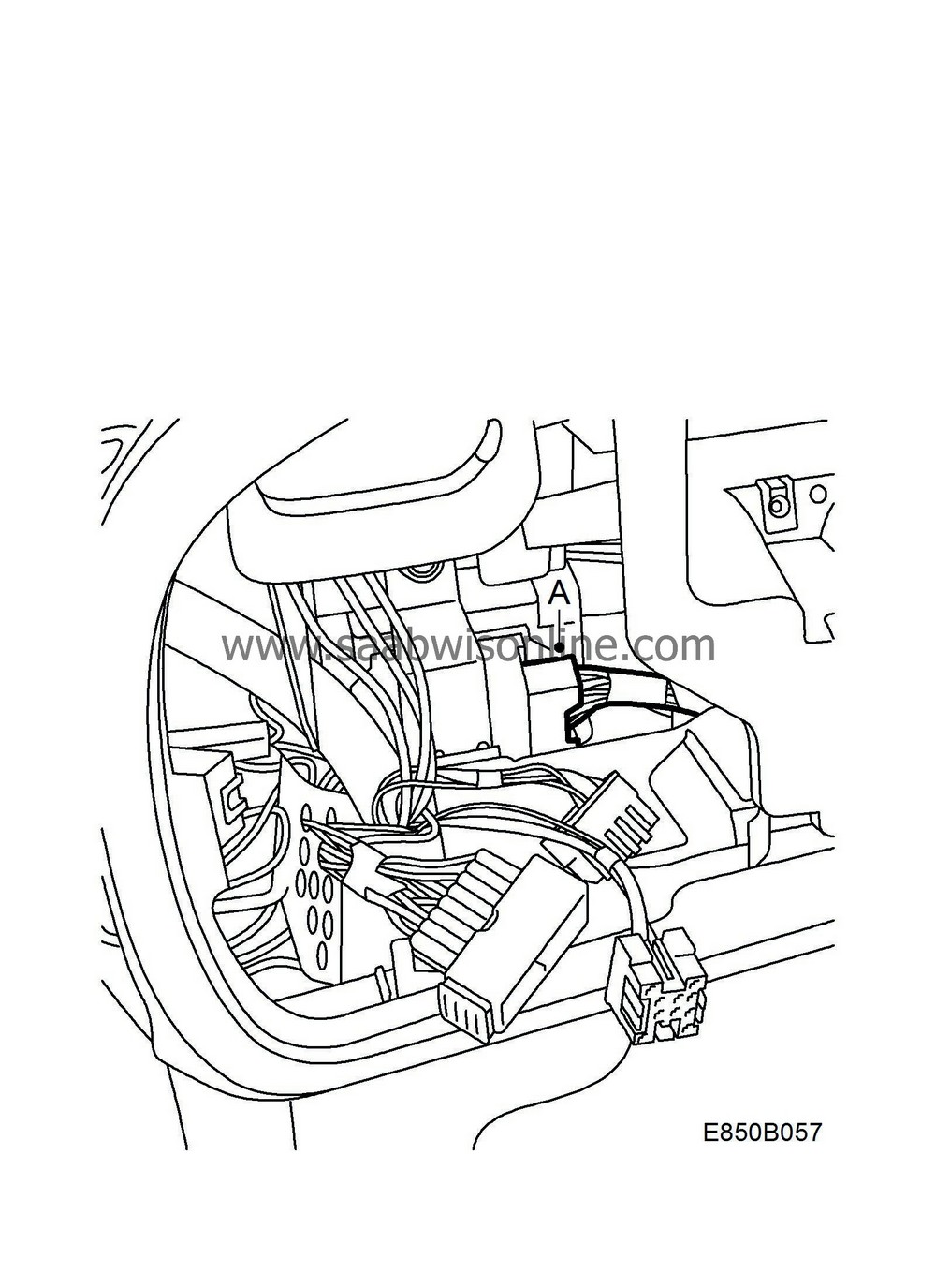
Remove and unplug the 33-pin connector (brown (A)).
|
|
9.
|
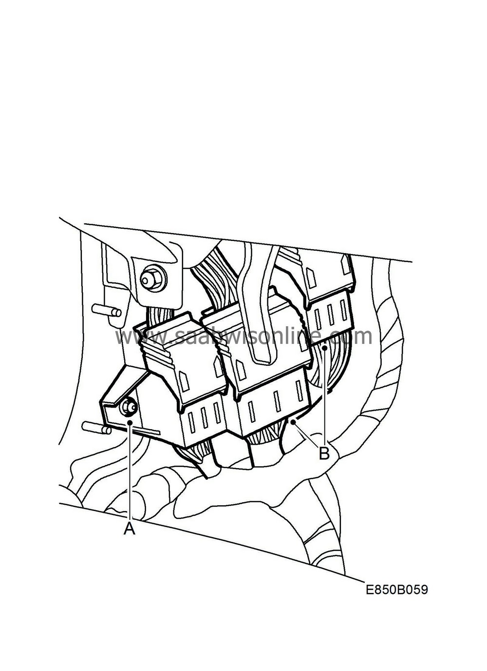
Unplug the connectors H80-1 and H43-1:
|
|
|
•
|
Undo the bracket (A), from the wall in front of the A-pillar.
|
|
|
•
|
Unplug H80-1 (green) and H43-1 (white) (B).
|
|
10.
|
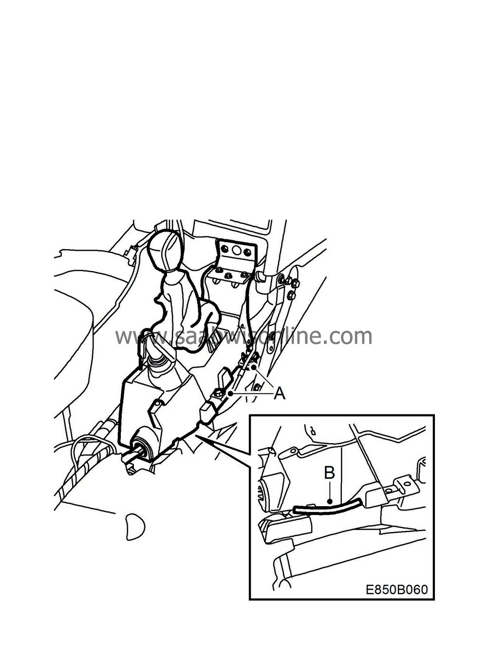
Loosen the gear lever housing (A).
AUT:
To access the gear lever housing screws more easily, unplug the 6-pin connector.
|
|
11.
|
Fit the protective moulding (82 78 558 (B)) on the lower edge of the gear lever housing, where the wiring harness enters under the gear lever housing.
|
|
12.
|
Route the new wiring harness along the normal wiring harness starting at the electronic unit, ACM. The wiring harness is routed under the normal wiring harness adjacent to the gear lever housing.
AUT:
The wiring harness is routed under the selector lever's plastic console.
|
|
13.
|
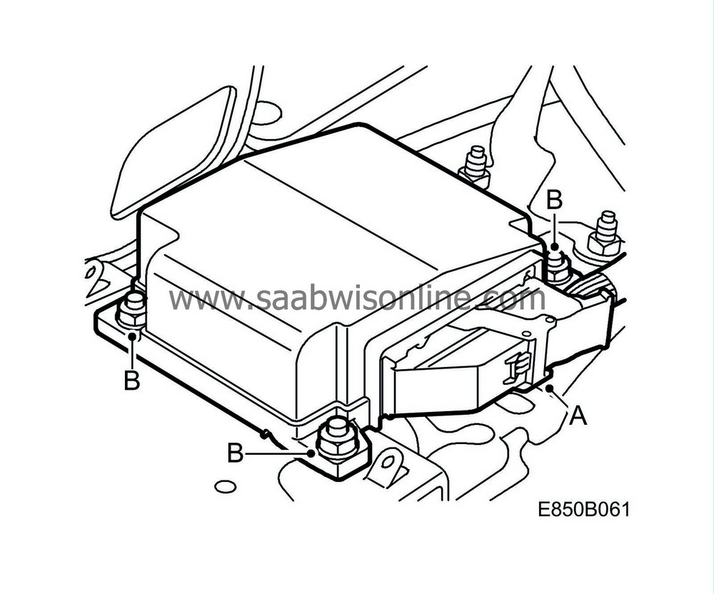
Connect the new wiring harness to the electronic unit, ACM (331):
|
|
|
•
|
Unplug the connector (A) from the electronic unit, ACM.
|
|
|
•
|
Remove the electronic unit, ACM (B).
|
|
|
•
|
Fit the new electronic unit (12 772 222).
|
|
|
•
|
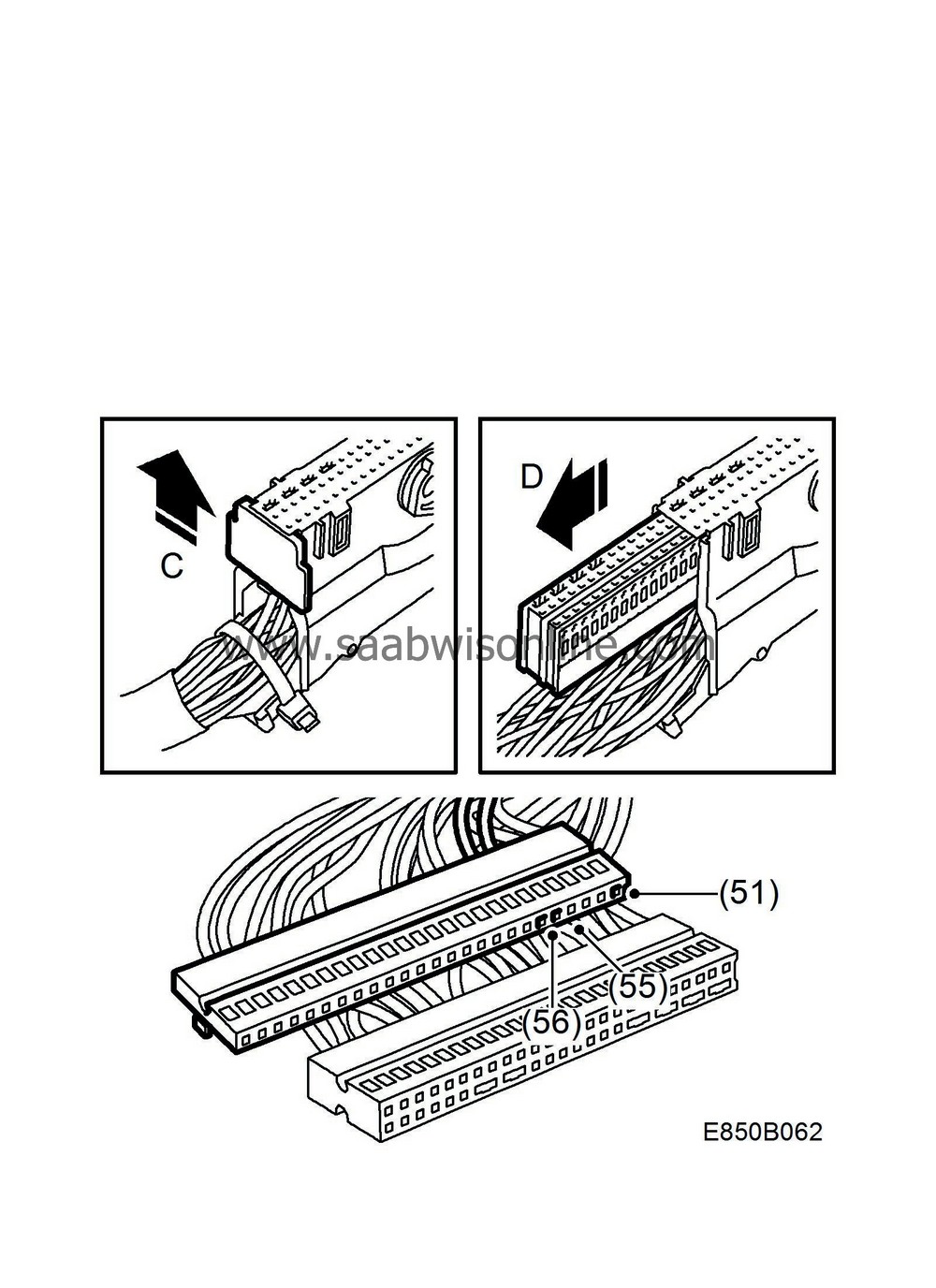
Cut off the cable tie, undo the connector's rear end face (C) and pull out the connecting rail (D).
|
|
|
•
|
Extract pin 51 (blue/red) and pin 57 (orange/white) from the new wiring harness, cut off and insulate.
|
|
|
•
|
Extract pin 51 from the old connector rail and insert it into the corresponding position in the new connector rail.
|
|
|
•
|
Extract pin 55 from the old connector rail and insert it into the corresponding position in the new connector rail.
|
|
|
•
|
Extract pin 56 from the old connector rail and insert it into the corresponding position in the new connector rail.
|
|
|
•
|
Cut off the remaining cables to the old connector rail and insulate.
|
|
|
•
|
Fit the connecting rail in the old connector and fit the end face.
|
Note
|
|
The new connector must not be used due to different anchorage points to the electronic unit, ACM.
|
|
|
|
•
|
Plug in the connector to the electronic unit ACM and secure the cables with a cable tie.
|
|
14.
|
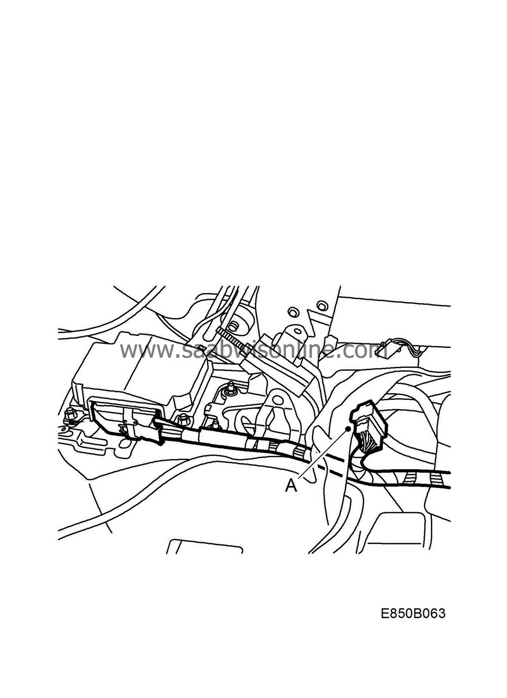
Change connection to H16-3:
|
|
|
•
|
Unplug H16-3 (black (A)) which is located under the mat, behind the gear lever housing.
|
|
|
•
|
Cut off the cables to the old connector and insulate.
|
|
|
•
|
Plug in the 16-pin connector from the new wiring harness to H16-3.
|
|
15.
|
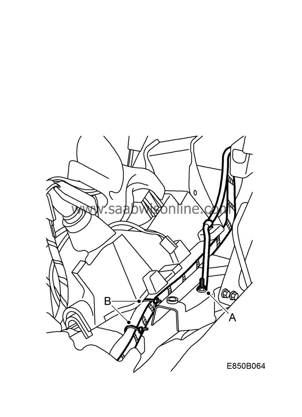
Replace the ground cable and secure the wiring harness:
|
|
|
•
|
Unscrew the old ground cable (A) at the gear lever housing. Cut off the old ground cable and insulate.
|
|
|
•
|
Fit the new ground cable to the grounding point and secure the wiring harness (B).
Tightening torque 9.5 Nm (7 lbf ft).
|
|
|
•
|
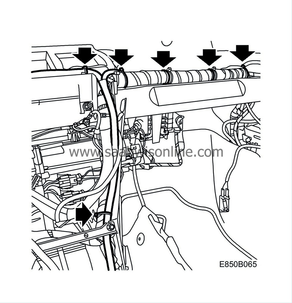
Route the branching from wiring harness that runs to the passenger airbag, along the normal wiring harness and secure with cable ties.
|
|
16.
|
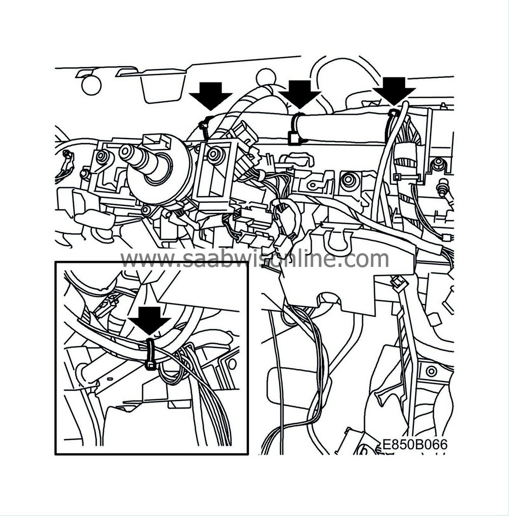
Route the branching from wiring harness that runs to the data link connector, fuse box and driver airbag connector, along the normal wiring harness and secure.
|
|
17.
|
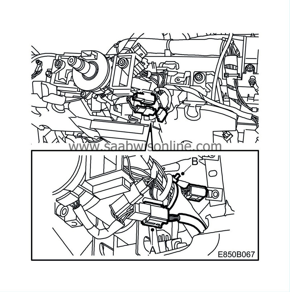
Cut off the driver airbag's old connector (333D(A)) with cable and insulate. Plug in the driver airbag's connector (A) and secure the cable (B) along the normal wiring harness. Make sure that there is no risk of chafing and that the steering wheel can be adjusted without problems.
|
|
18.
|
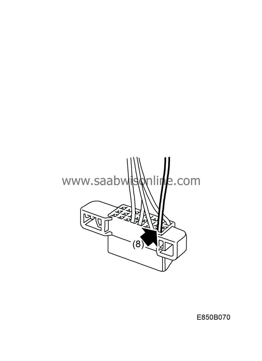
Extract position 8 from the data link connector, cut off and insulate. Insert the green cable from the new wiring harness. Secure the cable with cable ties and tape along the normal wiring harness.
|
|
19.
|
Cut off the blue/red cable from the new wiring harness and insulate.
|
|
20.
|
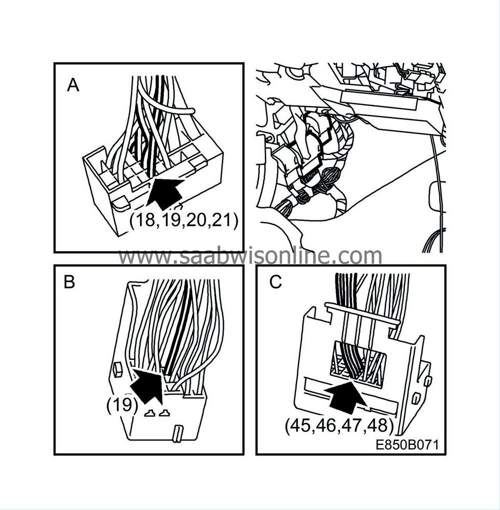
Connect the new wiring harness to connector H33-1 (brown), H43-1 (white) and H80-1 (green):
|
|
|
•
|
Route the wiring harness down towards the connector console. The wiring harness should be routed behind the relay box. Secure it and make sure that there is no risk of chafing.
|
|
|
•
|
Extract position 18, 19, 20 and 21 from H33-1(A). Cut off the old cables and insulate.
|
|
|
•
|
Insert the following cables from the new wiring harness in H33-1 (A): 18 (Blue), 19 (Grey/White), 20 (Green) and 21 (White).
|
|
|
•
|
Cut off the orange/white cable in the new wiring harness and insulate.
|
|
|
•
|
Unplug H43-1(B) and H80-1 (C). Cut off the cable ties so that the cables are accessible.
|
|
|
•
|
Remove the secondary catch from H43-1 (B), extract position no. 19. Cut off the cable and insulate.
|
|
|
•
|
Insert the new cable (Green) in position no. 19 and refit the secondary catch. Secure the new cable so that there is no risk of chafing.
|
|
|
•
|
Remove the secondary catch from H80-1 (C) and extract position 45, 46, 47 and 48. Cut off the cables and insulate.
|
|
|
•
|
Insert the following cables from the new wiring harness in H80-1 (C): 45 (Brown/Yellow), 46 (Red/Yellow), 47 (Green/Blue) and 48 (Yellow/Blue).
|
|
|
•
|
Secure and tape so that there is no risk of chafing.
|
|
|
•
|
Secure the wiring harnesses with new cable ties to the respective connectors.
|
|
|
•
|
Plug in the connectors (B) and screw back the console (A).

|
|
21.
|
Fit the centre console:

|
|
|
•
|
Position the centre console (C).
|
|
|
•
|
Fit the rear screws (B).
|
|
|
•
|
Fit the front screws (A).
|
|
22.
|
Fit the passenger airbag (12 757 093) in accordance with WIS - Body - Airbag (SRS) - Adjustment/Replacement.
|
Note
|
|
Use a new dashboard (12 774 268), screw (79 72 607) and nuts (11 900 439).
|
|
When fitting the passenger airbag nuts (11 900 439) to the dashboard (WIS-instruction pt 2) the following torque should be used: 10 Nm (7,5 lbf ft)
|
|
When refitting the passenger airbag screw (79 72 607) to the steering wheel member (WIS-instruction pt 19), the following torque should be used: 7 Nm (5 lbf ft)
|
|
Spare parts program the electronic unit ACM before clearing the diagnostic trouble codes.
|
|
|
23.
|
Fit the front passenger seat in accordance with WIS - Body - Seats - Front seat - Adjustment/Replacement.
|
|
24.
|
Apply the airbag label (54 65 596) to the cover located on the right-hand end of the dashboard.
|
|
Marking the modification identity plate
|
After carrying out the procedure, box B2 on the modification identity plate must be marked. From and including M04 the car's Warranty and Service Book contains the "Table of Modifications". Mark the box with the number "7" if the procedure was carried out by the importer or with the number "8" if carried out by the dealer.
|
Fitting the modification identity plate
|
|
Note
|
|
A modification identity plate must only be fitted where local directives require the marking of the car.
|
Fit the modification identity plate in accordance with WIS
9-5 M04 - General - General - Technical data - Plates and labels
|
Warranty/Time Information
|
See separate information.


