(854-2411 utg. 2) Cabin temperature cannot be changed on either the right or the left-hand side, not applicable to air control
Symptom: Cabin temperature cannot be changed on either the right or the left-hand side.
Diagnostic trouble codes B2295 and B2495 may be generated (up to and including Vehicle Identification Number 43014440).
|
TECHNICAL SERVICE BULLETIN
|
|
Bulletin Nbr:
|
854-2411 utg. 2
|
|
Date:
...........
|
April 2006
|
|
Market:
|
US/CA
|
|
|
Cabin temperature cannot be changed on either the right or the left-hand side, not applicable to air control
|
Before this TSB can be used, one of the TSBs numbered 854-2577, 854-2578, 854-2579 or 854-2580 must be used for fault diagnosis as well as for the procedure if possible.
All 9-5 M98-
This service information only applies if one of the shutter shafts for the heater is broken in accordance with step 28 in TSB 854-2577 or step 31 in TSB 854-2578, or is pressed into the heating and ventilation unit. Not applicable to shutter shafts for air distribution. For action relating to air distribution, see TSB 854-2461.
Symptom description
Cabin temperature cannot be changed on either the right or the left-hand side.
Diagnostic trouble codes B2295 and B2495 may be generated (up to and including Vehicle Identification Number 43014440).
Parts required for removed heating and ventilation unit. (Parts required for removing/fitting heating and ventilation unit not included.)
9-5 M98-M02 up to and including Vehicle Identification Number 23058288
53 36 664 (CA: 30592689) Service kit, Heat exchanger housing
79 71 864 (CA: 30509025) Cable tie (x 2)
See "Decide which method must be employed" (below), to determine which method is relevant.
9-5 M02- from and including Vehicle Identification Number 23058289
53 36 664 (CA: 30592689) Service kit, Heat exchanger housing
79 71 864 (CA: 30509025) Cable tie (x 2)
Use method B.
Procedure
Method A, see page 3
Method B, see page 13
Decide which method must be employed:
|
1.
|
Remove the cover for the heating and ventilation unit under the glove box.
|
|
2.
|
Remove the lower section of the dashboard under the glove box, 4 screws. There are clips in the front edge.
|
|
3.
|
Fold aside the carpet so that the cover over the rear valves is exposed.
|
|
4.
|
Check what type of cover(s) is/are fitted over the rear valves and over the heat exchanger.
|
|
|
4.a.
|
If there are 2 small covers, choose method A.

|
|
|
4.b.
|
If there is 1 large cover, choose method B.

|
|
1.
|
Turn the ignition switch to the ON position.
|
|
2.
|
Engage distribution mode VENT. Wait until the system has stabilised, (approx. 30 seconds).
|
|
3.
|
Turn the ignition key to the OFF position.
|
|
4.
|
Remove the heating and ventilation unit from the car, as described in WIS 9-5 M98 - 8. Body - Heating and ventilation, A/C - Adjustment/Replacement - Climate control unit.
|
|
5.
|
Remove the foam seal from around the fan unit.

|
|
6.
|
Up to M04 inclusive:
Remove the plate holding the connectors on the passenger side. For models with temperature sensor, remove the temperature sensor's connector from the plate. The connector's wiring harness enters the heating and ventilation unit via a rubber grommet.
Remove the fan control unit on the driver's side. For models with a transparent water barrier in front of the fan control module, this must be removed first.

|
|
7.
|
From M05 inclusive:
Remove the large connector for the fan control unit on the passenger side.
Remove the fan control unit on the passenger side by removing the 2 screws.

|
|
8.
|
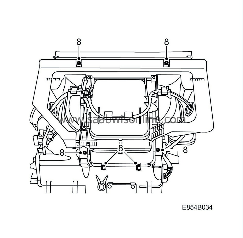
Remove the 4 screws and the 2 clips and remove the fan housing.
|
|
9.
|
Up to VIN 43003168 inclusive:
Make a note and mark which connector is connected to which stepping motor. In some cases the cables are already marked, see To fit. Mark up on which side each temperature sensor is located. The temperature sensors must not be mixed up when fitting.

From VIN 43003169 inclusive:
Make a note and mark which connector is connected to which stepping motor. In some cases the cables are already marked, see To fit. Mark up on which side each temperature sensor is located. The temperature sensors are removed by twisting them and they must not be mixed up when fitting.
|
|
10.
|
Unplug the wiring harness and cut the cable ties. Remove the wiring harness.
|
Note
|
|
Up to VIN 43003168 inclusive:
Take care that the catches holding the temperature sensors do not break.
|
|
|
11.
|
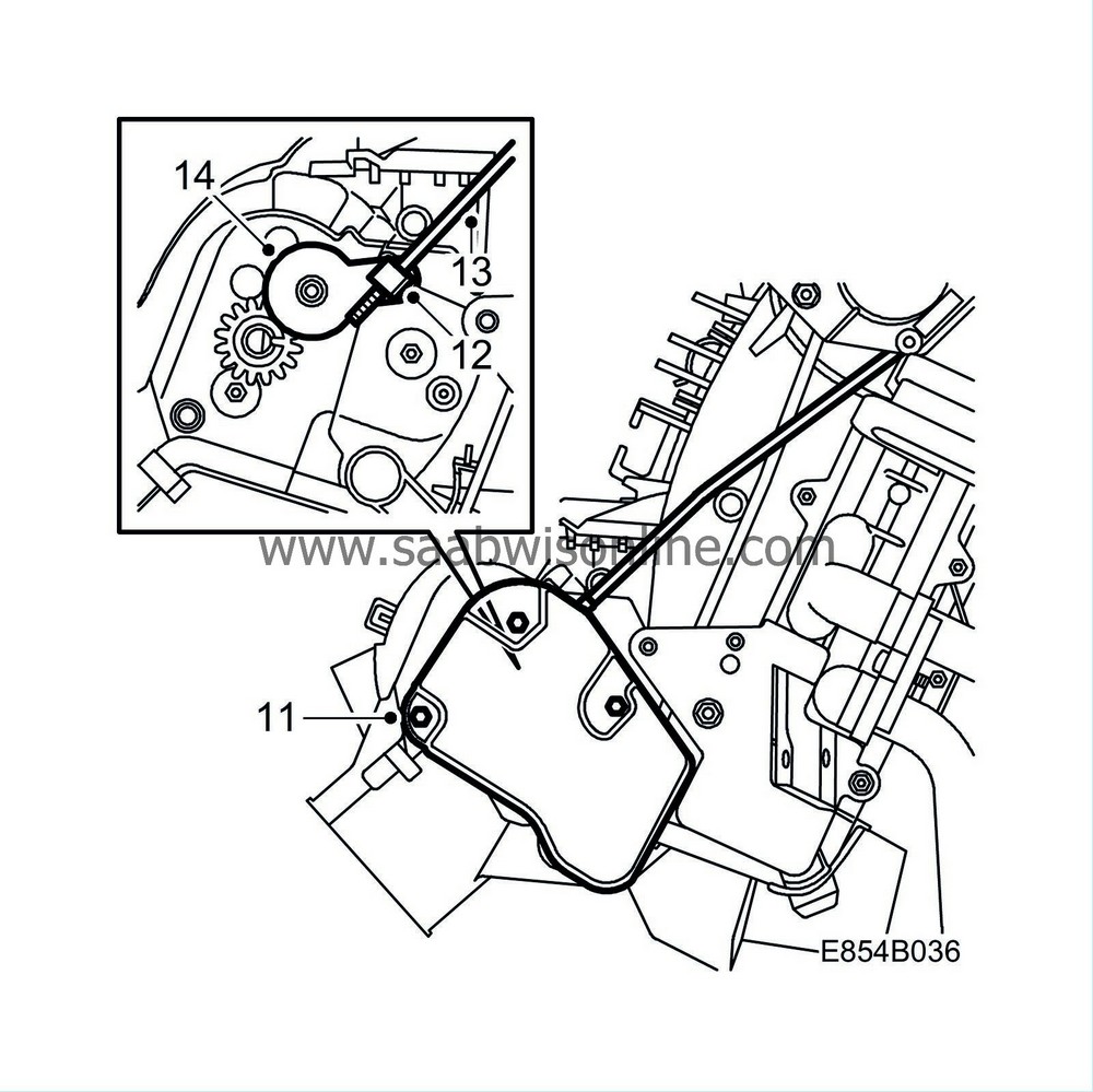
Remove the 3 screws from the cover and remove the cover.
|
|
12.
|
Carefully open the clasp securing the control rod to the rear air distribution valve.
|
|
13.
|
Remove the control rod from the rear air distribution valve.
|
|
14.
|
Remove the gear with clip.
|
Note
|
|
The gear shall not be used with fitting.
|
|
|
15.
|
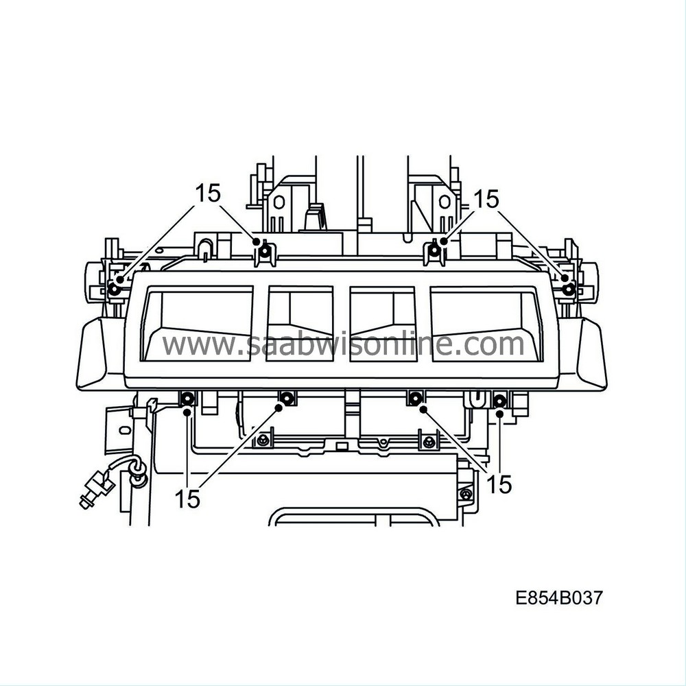
Remove the 8 air distributor housing screws.
|
|
16.
|
Carefully lift aside the air distributor housing.
|
Note
|
|
Exercise care to prevent the control rod from catching and damaging anything.
|
|
|
17.
|
Remove the pipes from the heat exchanger.

|
|
18.
|
Remove the 4 screws and the 2 clips from the front and right-hand side of the heat exchanger housing.

|
|
19.
|
Remove the screw and the 2 clips from the left-hand side of the heat exchanger housing.

|
|
20.
|
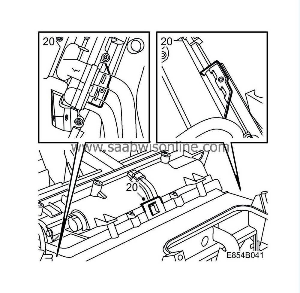
Remove the heat exchanger housing by opening the 3 plastic catches. Lift away the heat exchanger housing from the evaporator casing. Clean the drain hole and bottom of the evaporator casing.
|
|
21.
|
Remove the collar from the air outlet.

|
|
22.
|
Remove the 2 lower screws and cover over the heat exchanger.
|
|
23.
|
Remove the 2 upper screws that hold the heat exchanger.
|
|
24.
|
Carefully pull out the heat exchanger.
|
|
1.
|
Remove the collar from the new air distributor housing.
|
|
2.
|
Remove the 2 screws and cover from the new heat exchanger housing.

|
|
3.
|
Fit the heat exchanger by carefully pushing in the new heat exchanger housing and fitting the 2 upper screws.
Tightening torque 1.4 Nm (1 lbf ft)

|
Note
|
|
Be careful when the heat exchanger is pushed into the heat exchanger housing as the space between the heat exchanger and the upper cam disc is limited.
|
|
|
4.
|
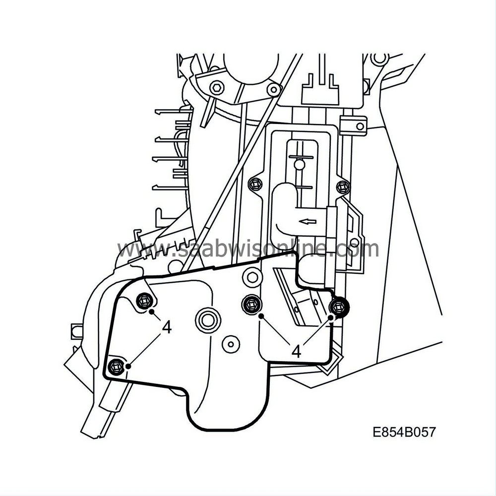
Fit the new cover with the 4 screws at the rear air distribution valve. Start with the upper rear screw, then with the lower rear screw.
Tightening torque 1.4 Nm (1 lbf ft)
|
Note
|
|
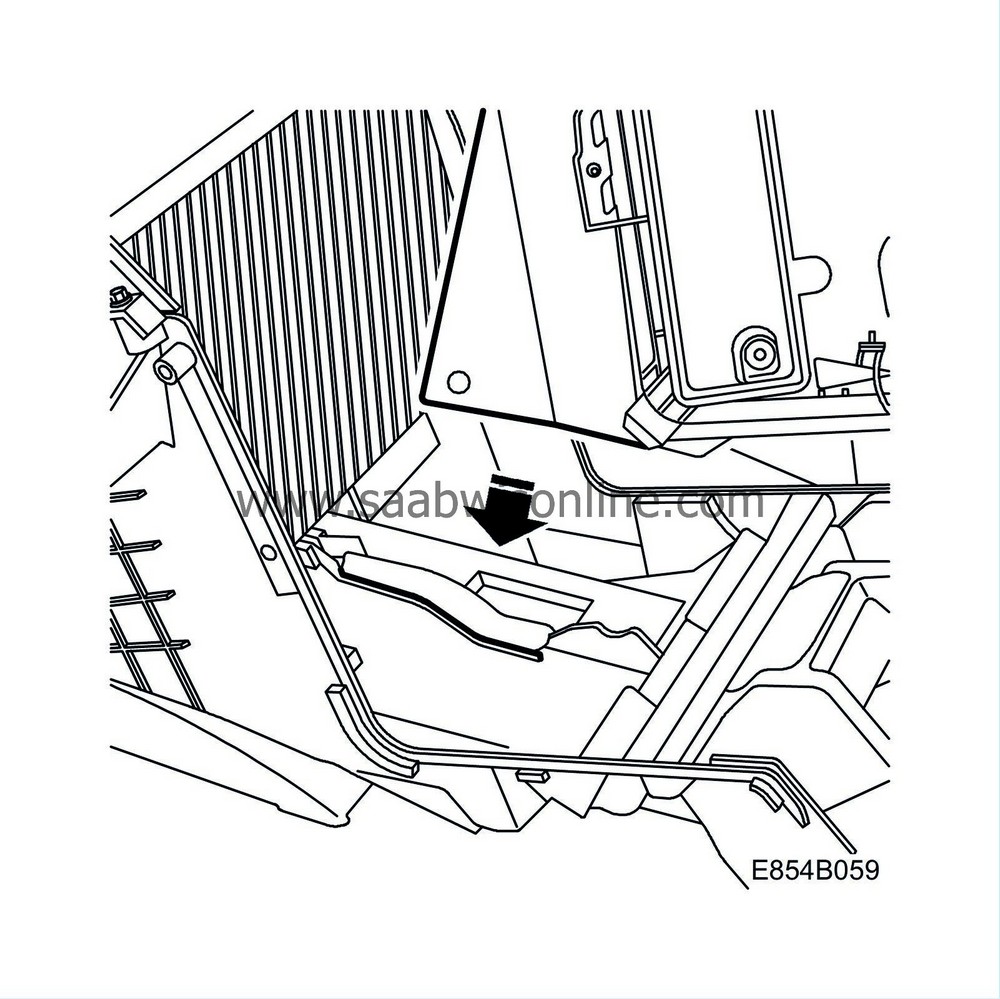
Make sure that the air shield on the heat exchanger housing is set against the seal (certain models) and the guide inside the evaporator casing when the heat exchanger housing is fitted.
|
|
|
5.
|
Fit the new heat exchanger housing onto the evaporator casing and fit the 4 screws and the 2 clips to the front and right-hand side of the heat exchanger housing.
Tightening torque 1.4 Nm (1 lbf ft)

|
|
6.
|
Fit the screw and the 2 clips to the left-hand side of the heat exchanger housing.

|
|
7.
|
Fit the collar to the air outlet.
|
|
8.
|
Fit new O-rings greased with synthetic vaseline, part no. 30 15 286, on the heat exchanger pipes and fit the pipes to the heat exchanger. Exercise care that the O-rings are not damaged.
Tightening torque 3.5 Nm (2.6 lbf ft).

|
|
9.
|
Remove the stepping motor from the old air distributor housing and remove the control rod from its clip.

|
Note
|
|
The old control rod shall not be used with fitting.
|
|
|
10.
|
Press down the control rod to its lowest position.

|
|
11.
|
Locate the air distributor housing into its position and fit the screws.
Tightening torque 1.4 Nm (1 lbf ft)
|
|
12.
|
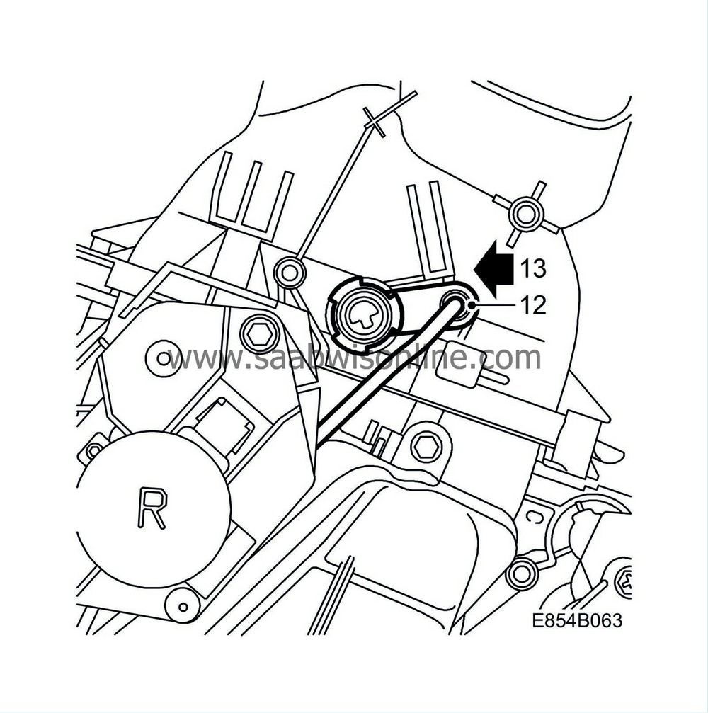
Fit the upper section of the new control rod in its clip.
|
|
13.
|
Wind up the linkage to the stepping motor in the air distributor housing to the upper stop.
|
|
14.
|
Fit the stepping motor and its 2 screws on the air distributor housing.
|
|
15.
|
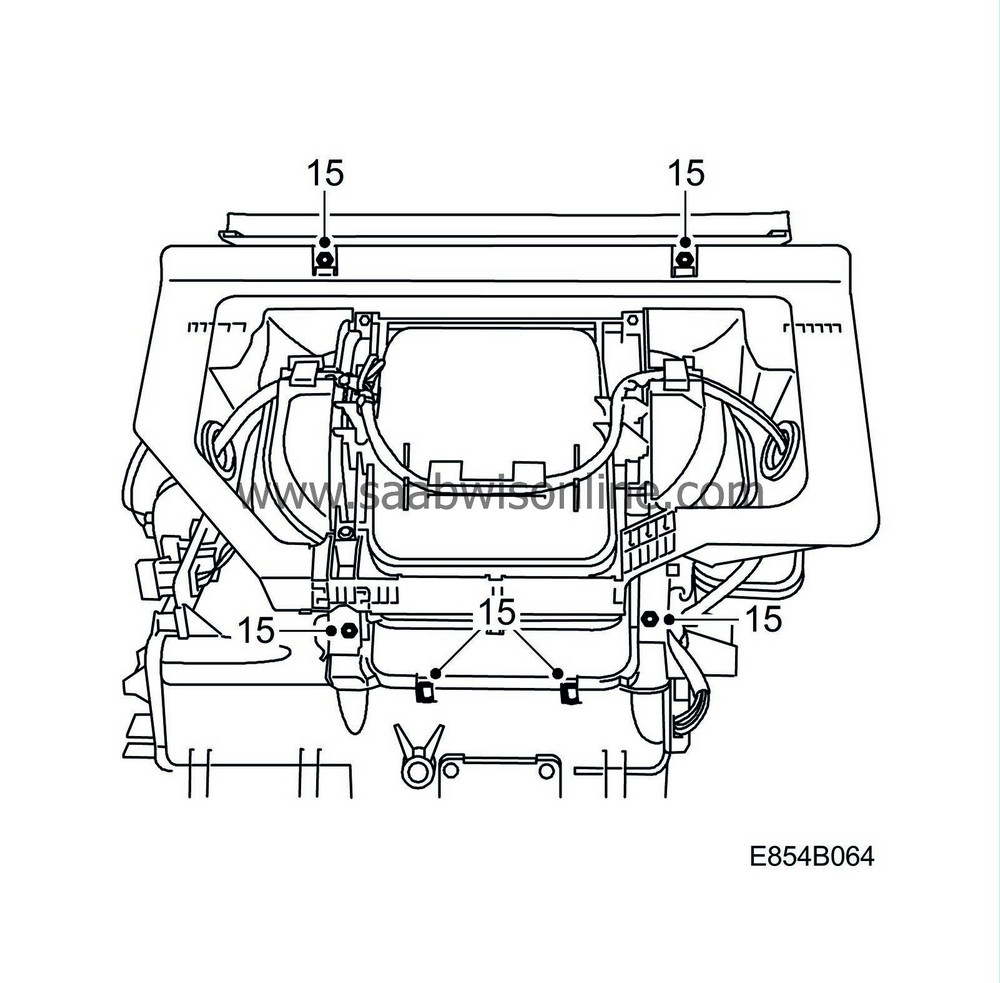
Locate the fan housing into its position and fit the screws to the cabin fan housing and fit the 2 clips.
Tightening torque 1.4 Nm (1 lbf ft)
|
|
16.
|
Up to M04 inclusive:
Fit the fan control module and route the wiring up under the clasp. Where applicable, fit the water barrier.
Where appropriate, fit the temperature sensor connector to the plate and fit the plate to the heat exchanger housing. Make sure to guide the rubber grommet into the plate.

|
|
17.
|
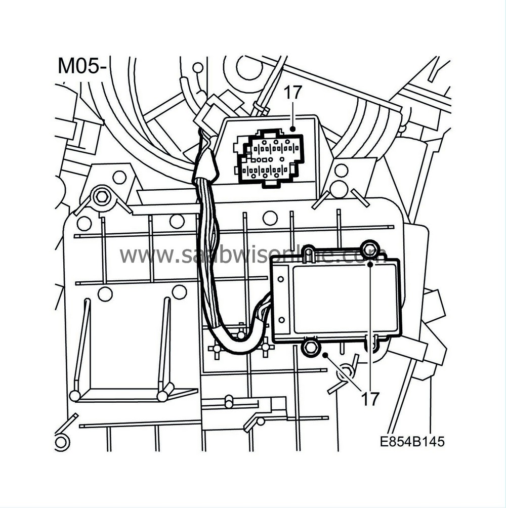
From M05 inclusive:
Fit the fan control module and make a point of routing the wiring under the clip for the filter cover.
Tightening torque 1.4 Nm (1 lbf ft)
Fit the large connector to the fan control unit.
|
|
18.
|
Fit a new foam seal around the fan housing.

|
|
19.
|
Fit and connect the wiring harness, and where appropriate, where the cables to the stepping motors are already marked with tape, the following applies:

Stepping motor distribution, blue tape
Blend Stepping motor, left-hand side, brown tape
Blend Stepping motor, right-hand side, red tape
|
|
20.
|
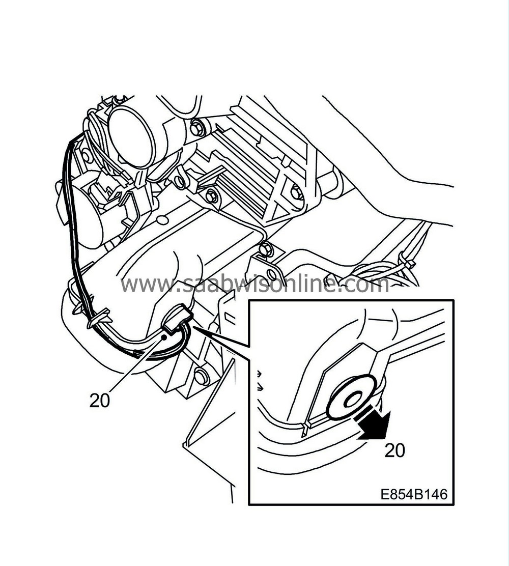
Up to VIN 43003168 inclusive:
Carefully make holes using the temperature sensors and position them. Secure the wiring harness with cable ties.

From VIN 43003169 inclusive:
Remove the plug on the air duct. Fit the temperature sensors by twisting and pressing them in. Secure the wiring harness with cable ties.
|
|
21.
|
Fit the heating and ventilation unit, as described in WIS 9-5 M98 - 8. Body - Heating and ventilation, A/C - Adjustment/Replacement - Climate control unit.
|
|
22.
|
Replace and lubricate the O-rings on the pipes to the compressor and the condenser using synthetic vaseline, part no. 30 15 286. Exercise care that the O-rings are not damaged.
|
|
23.
|
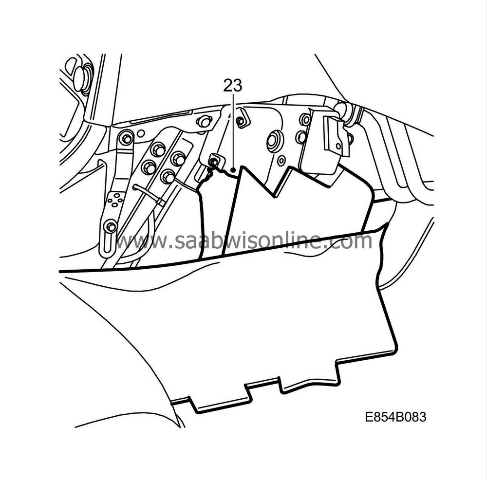
In the event that sound insulation shall be fitted:
|
Note
|
|
Sound insulation will not have the same fit as before, this will not affect sound insulation.
|
|
|
1.
|
Turn the ignition switch to the ON position.
|
|
2.
|
Engage distribution mode VENT. Wait until the system has stabilised, (approx. 30 seconds).
|
|
3.
|
Turn the ignition key to the OFF position.
|
|
4.
|
Remove the heating and ventilation unit from the car, as described in WIS 9-5 M02- 8. Body - Heating and ventilation, A/C - Adjustment/Replacement - Climate control unit.
|
|
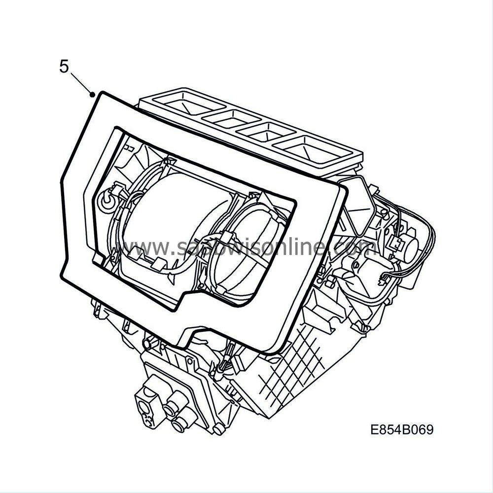
5.
|
Remove the foam seal from around the fan unit.
|
|
6.
|
Up to M04 inclusive:
Remove the plate holding the connectors on the passenger side. For models with temperature sensor, remove the temperature sensor's connector from the plate. The connector's wiring harness enters the heating and ventilation unit via a rubber grommet.
Remove the fan control unit on the driver's side. For models with a transparent water barrier in front of the fan control module, this must be removed first.

|
|
7.
|
From M05 inclusive:
Remove the large connector for the fan control unit on the passenger side.
Remove the fan control unit on the passenger side by removing the 2 screws.

|
|
8.
|
Remove the 4 screws and the 2 clips and remove the fan housing.

|
|
9.
|
Up to VIN 43003168 inclusive:
Make a note and mark which connector is connected to which stepping motor. In some cases the cables are already marked, see To fit. Mark up on which side each temperature sensor is fitted. The temperature sensors must not be mixed up when fitting.
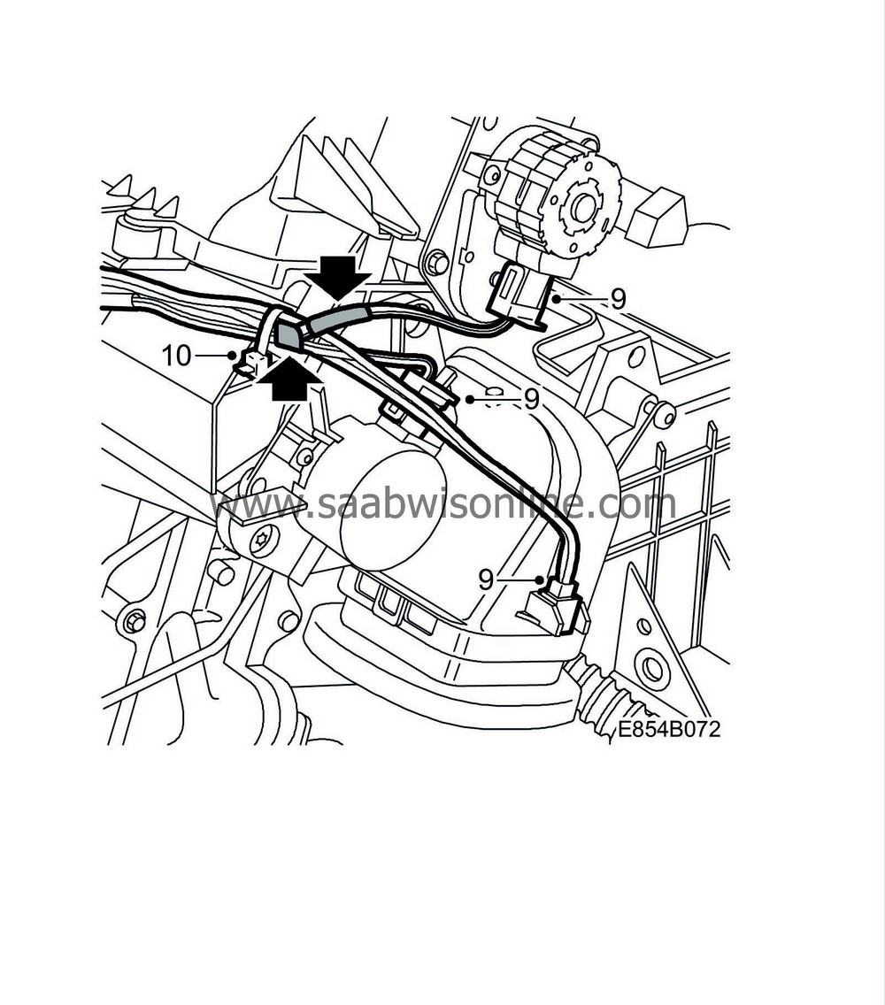
From VIN 43003169 inclusive:
Make a note and mark which connector is connected to which stepping motor. In some cases the cables are already marked, see To fit. Mark up on which side each temperature sensor is located. The temperature sensors are removed by twisting them and they must not be mixed up when fitting.
|
|
10.
|
Unplug the wiring harness and cut the cable ties. Remove the wiring harness.
|
Note
|
|
Up to VIN 43003168 inclusive:
Take care that the catches holding the temperature sensors do not break.
|
|
|
11.
|
Remove the 4 screws from the cover and remove the cover.

|
|
12.
|
Carefully remove the upper cam disc.

|
|
13.
|
Carefully remove the gear that the control rod is fixed into, from the heat exchanger housing.
|
|
14.
|
Remove the gear from the control rod.
|
|
15.
|
Remove the screws from the air distributor housing.

|
|
16.
|
Carefully lift aside the air distributor housing.
|
Note
|
|
Exercise care to prevent the control rod from catching and damaging anything.
|
|
|
17.
|
Remove the pipes from the heat exchanger.

|
|
18.
|
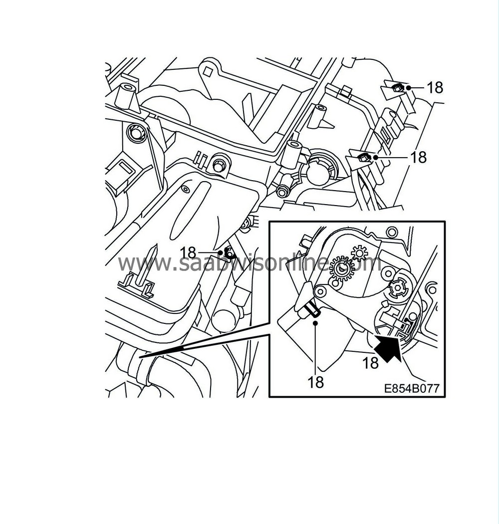
Remove the 4 screws and the 2 clips from the front and right-hand side of the heat exchanger housing.
|
|
19.
|
Remove the screw and the 2 clips from the left-hand side of the heat exchanger housing.

|
|
20.
|
Remove the heat exchanger housing by opening the 3 plastic catches. Lift away the heat exchanger housing from the evaporator casing. Clean the drain hole and bottom of the evaporator casing.

|
|
21.
|
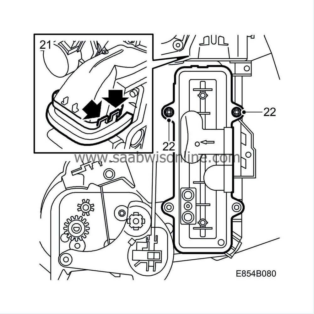
Remove the collar from the air outlet.
|
|
22.
|
Remove the 2 remaining screws that hold the heat exchanger. Carefully pull out the heat exchanger.
|
Note
|
|
Be careful when the heat exchanger is removed from the heat exchanger housing as the space between the heat exchanger and the upper cam disc is limited.
|
|
|
1.
|
Remove the collar from the new air distributor housing.
|
|
2.
|
Remove the 2 screws and cover from the new heat exchanger housing.

|
|
3.
|
Fit the heat exchanger by carefully pushing in the new heat exchanger housing and fitting the 2 upper screws.
Tightening torque 1.4 Nm (1 lbf ft)

|
Note
|
|
Be careful when the heat exchanger is pushed into the heat exchanger housing as the space between the heat exchanger and the upper cam disc is limited.
|
|
|
4.
|
Fit the new cover with the 4 screws at the rear air distribution valve. Start with the upper rear screw, then with the lower rear screw.
Tightening torque 1.4 Nm (1 lbf ft)

|
Note
|
|
Make sure that the air shield on the heat exchanger housing is set against the seal (certain models) and the guide inside the evaporator casing when the heat exchanger housing is fitted.
|

|
|
5.
|
Fit the new heat exchanger housing onto the evaporator casing and fit the 4 screws and the 2 clips to the front and right-hand side of the heat exchanger housing.
Tightening torque 1.4 Nm (1 lbf ft)

|
|
6.
|
Fit the screw and the 2 clips to the left-hand side of the heat exchanger housing.

|
|
7.
|
Fit the collar to the air outlet.
|
|
8.
|
Fit new O-rings greased with synthetic vaseline, part no. 30 15 286, on the heat exchanger pipes and fit the pipes to the heat exchanger. Exercise care that the O-rings are not damaged.
Tightening torque 3.5 Nm (2.6 lbf ft).

|
|
9.
|
Remove the stepping motor from the old air distributor housing and remove the control rod from its clip.

|
Note
|
|
The old control rod shall not be used with fitting.
|
|
|
10.
|
Press down the control rod to its lowest position.
|
|
11.
|
Locate the air distributor housing into its position and fit the screws.

Tightening torque 1.4 Nm (1 lbf ft)
|
|
12.
|
Fit the upper section of the new control rod in its clip.

|
|
13.
|
Wind up the linkage to the stepping motor in the air distributor housing to the upper stop.
|
|
14.
|
Fit the stepping motor and its 2 screws to the air distributor housing.
|
|
15.
|
Locate the fan housing into its position and fit the screws to the cabin fan housing and fit the 2 clips.

Tightening torque 1.4 Nm (1 lbf ft)
|
|
16.
|
Up to M04 inclusive:
Fit the fan control module and route the wiring up under the clasp. Where applicable, fit the water barrier.
Where appropriate, fit the temperature sensor connector to the plate and fit the plate to the heat exchanger housing. Make sure to guide the rubber grommet into the plate.

|
|
17.
|
From M05 inclusive:
Fit the fan control module and make a point of routing the wiring under the clip for the filter cover.
Tightening torque 1.4 Nm (1 lbf ft)
Fit the large connector to the fan control unit.

|
|
18.
|
Fit a new foam seal around the fan housing.

|
|
19.
|
Fit and connect the wiring harness, and where appropriate, where the cables to the stepping motors are already marked with tape, the following applies:

Stepping motor distribution, blue tape
Blend Stepping motor, left-hand side, brown tape
Blend Stepping motor, right-hand side, red tape
|
|
20.
|
Up to VIN 43003168 inclusive:
Carefully make holes using the temperature sensors and position them. Secure the wiring harness with cable ties.

From VIN 43003169 inclusive:
Remove the plug on the air duct. Fit the temperature sensors by twisting and pressing them in. Secure the wiring harness with cable ties.

|
|
21.
|
Fit the heating and ventilation unit as described in WIS. See WIS 9-5 Body - Heating and ventilation, A/C - Adjustment/Replacement - Climate control unit.
|
|
22.
|
Replace and lubricate the O-rings on the A/C pipes from the expansion valve using synthetic vaseline, part no. 30 15 286. Exercise care that the O-rings are not damaged.
|
|
23.
|
In the event that the sound insulation shall be fitted:
|
Note
|
|
Sound insulation will not have the same fit as before. The sound insulation is not affected by this.
|

|
|
Time/Warranty information
|
To resolve a customer complaint for a vehicle
in warranty
, submit a claim using the following information:
Failed object: 85440
Fault/Reason code: 32
Location code: 09 (US=0)
Warranty Type (US): 01
Repair/Action code: 01
Labour Operation (US): 8544003
Labour Operation (CA): D2109 (9.2 hrs excl. draining and charging the A/C system)
Time: 9.2 hours + draining and charging the A/C system 1.3 hours


