Steering wheel controls
| Steering wheel controls |

| General |
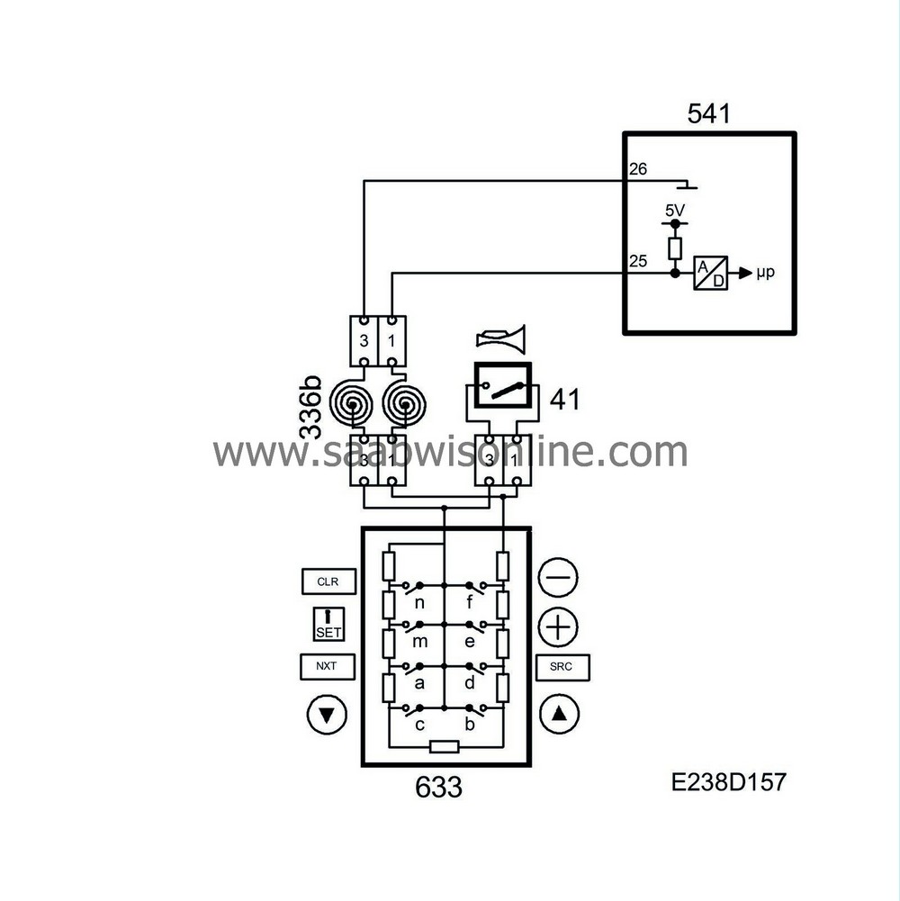
The steering wheel control consists of 3 units (9 switches) which are mounted in the steering wheel and airbag control module. The steering wheel control provides the SID control module with information defining which switch is activated.
The SID control module supplies +5V to the steering wheel controls via pin 25 and grounds them via pin 26.
The 9 steering wheel switches consist of 9 resistors connected in series. When a button is pressed, the relevant switch is grounded; see table below.
The value of the total resistance in the circuit changes according to which switch is depressed and there is a corresponding change in the voltage which is sensed by the SID control module.
The horn switch (41) is connected in parallel with the steering wheel switches. When it is pressed, pin 25 is grounded directly to pin 26.
The table shows the correlation between the voltage on pin 25 and the identity of the active switch.
|
Switch
|
Voltage (V)
|
Resistance (Ohms)
|
|
Horn
|
0
|
0
|
|
VOL -
|
1.3
|
31
|
|
VOL +
|
1.7
|
70
|
|
SRC (select audio source)
|
2.1
|
120
|
|
Arrow up (search forwards)
|
2.5
|
187
|
|
Arrow down (search backwards)
|
2.9
|
280
|
|
NXT (settings for audio sources)
|
3.3
|
420
|
|
i-SET
|
3,7
|
652
|
|
CLR
|
4,1
|
1116
|
|
Normal
|
4,5
|
2516
|
The SID control module uses the information from the steering wheel controls to activate the horn and to send bus information for both the information display and the audio functions.
| Diagnosis |
In the event of an open/short-circuit to B+ or a short-circuit to ground for more than 5 min, DTC B2371 is generated.


