Suspension arm
| Suspension arm |
| To remove |
| 1. |
Raise the car.
If a jack is used, safety stands should be placed under the car. |
|
| 2. |
Remove the front wheel.
|
|
| 3. |
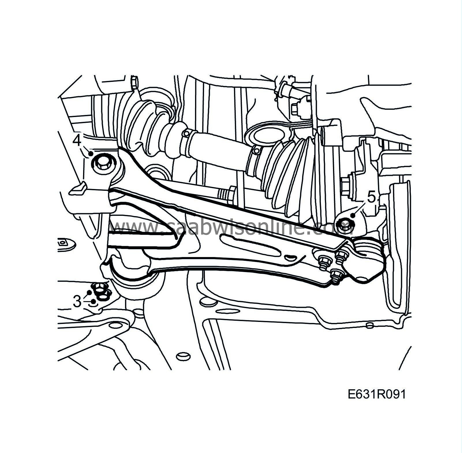
Remove the rear suspension arm mounting from the subframe.
|
|
| 4. |
Remove the front suspension arm mounting from the subframe.
|
|
| 5. |
Remove the ball joint from the steering swivel member.
|
|
| 6. |
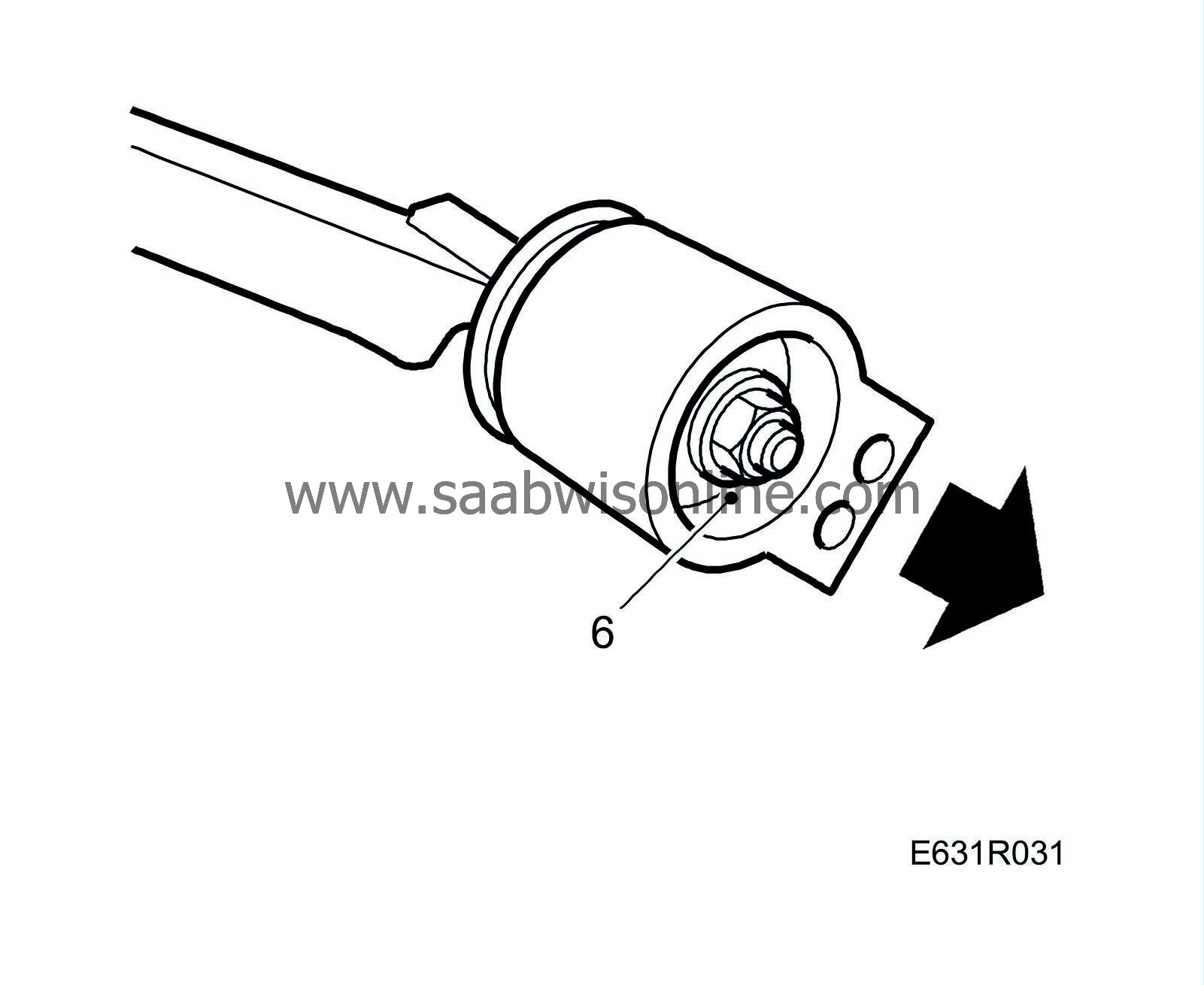
Remove the ball joint and the rear bush from the suspension arm.
|
|
| To fit |
| 1. |
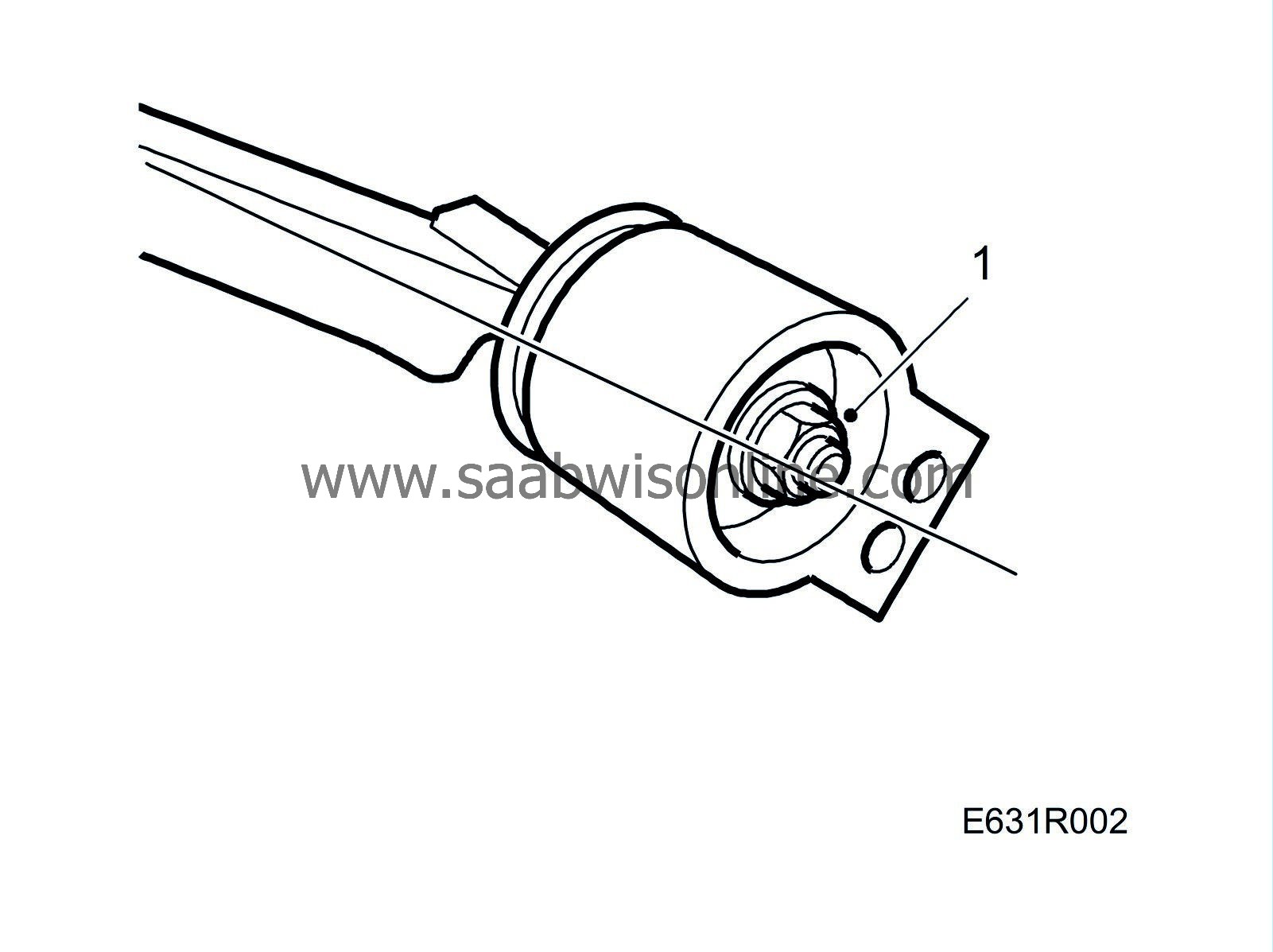
Fit
Suspension arm bushing, front.
Fit the rear bushing in line with the suspension arm.
Tightening torque 105 Nm (77 lbf ft) |
|
| 2. |
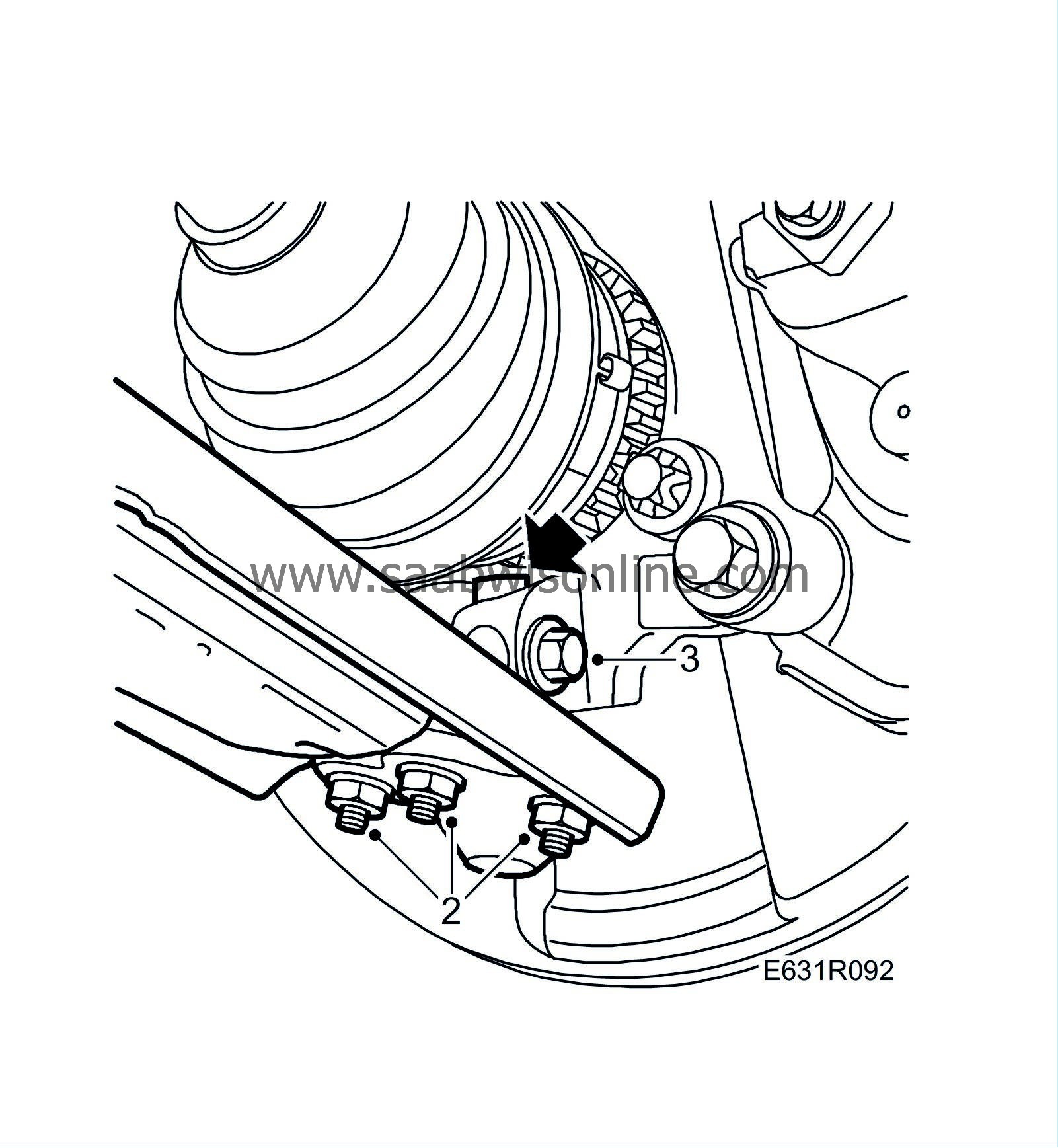
Fit the ball joint to the suspension arm.
Tightening torque 60 Nm +30° (22.5 lbf ft +30°) |
|
| 3. |
Fit the ball joint to the steering swivel member.
|
|||||||||
| 4. |
Position the suspension arm against the subframe and insert the bolts in the front and rear attachment points.
|
|
| 5. |
Raise the suspension arm with a jack to the same level as to when the car is on its wheels.
|
|
| 6. |
Tighten the bolts securing the front suspension mounting to the subframe.
Tightening torque 110 Nm +90° (81 lbf ft +90°) 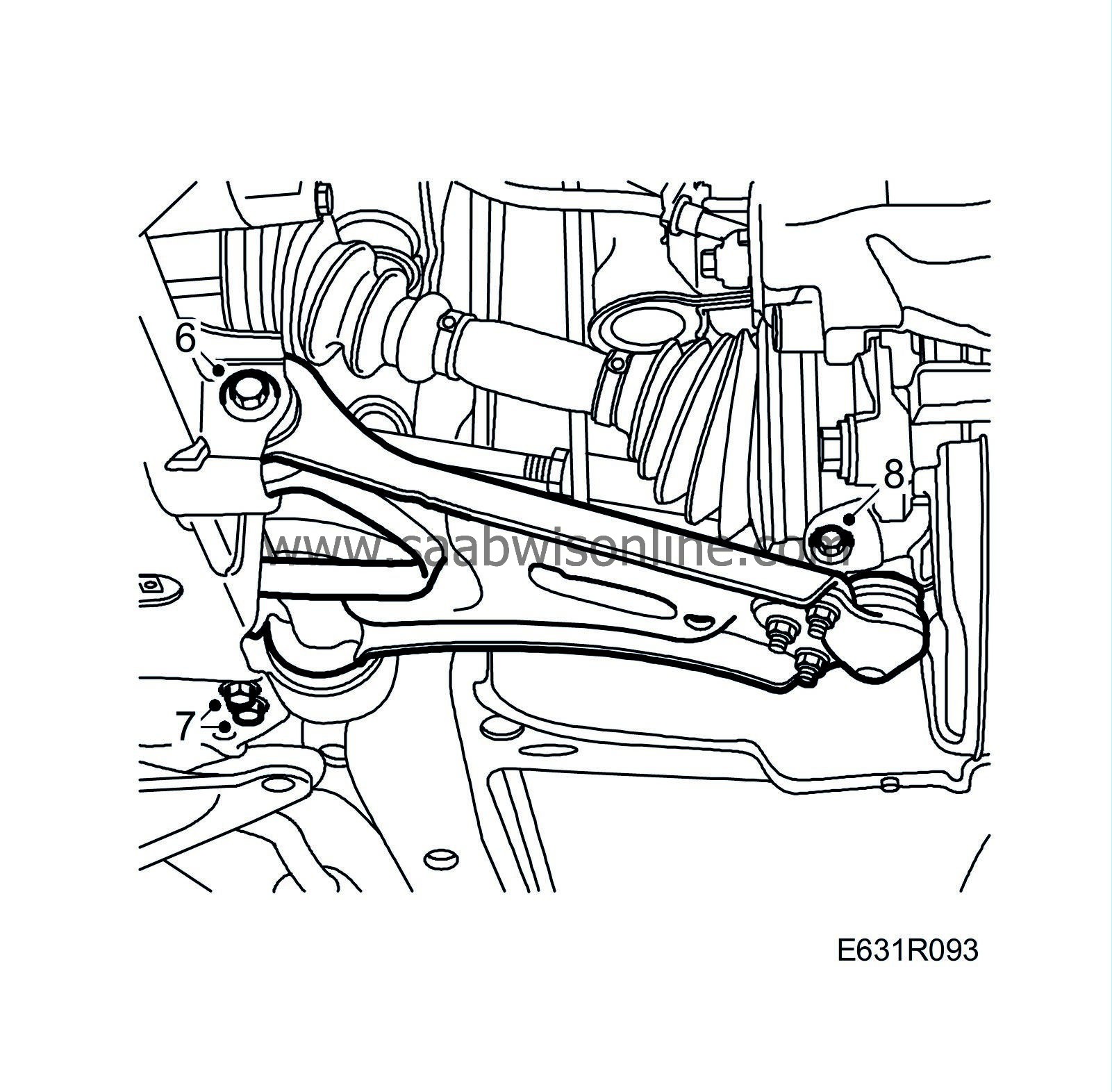
|
|
| 7. |
Tighten the bolts securing the rear suspension mounting to the subframe.
Tightening torque 120 Nm +90° (88 lbf ft +90°) |
|
| 8. |
Tighten the bolt securing the ball joint to the steering swivel member.
Tightening torque 49Nm (36 lbf ft) |
|
| 9. |
Fit the wheel. See
Wheels
.
Tightening torques aluminium wheel 110 Nm (81 lbf ft) steel wheel 50 Nm + 2x90°, max. 110 Nm (37 lbf ft + 2x90°, max. 81 lbf ft) Lower the car to the floor. |
|
| 10. |
Check the toe-in and adjust if necessary, see
Adjusting front toe angle
.
|
|

 Warning

