Detailed description of engine function.
| Detailed description of engine function. |
| Engine torque |
General
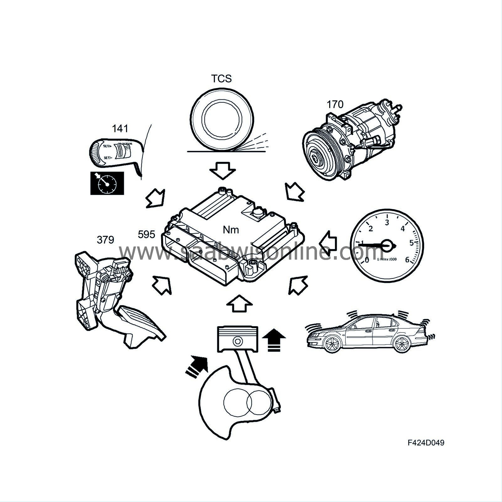
The purpose of engine torque control is to ensure that the engine supplies the correct amount of torque. The ECM controls engine torque by adjusting the quantity of injected fuel.The following functions can request engine torque:
| • |
Accelerator pedal
|
|
| • |
Cruise control
|
|
| • |
TCS/ESP
|
|
| • |
A/C and generator
|
|
| • |
Idle
|
|
| • |
Active surge dampening
|
|
| • |
Internal engine friction
|
|
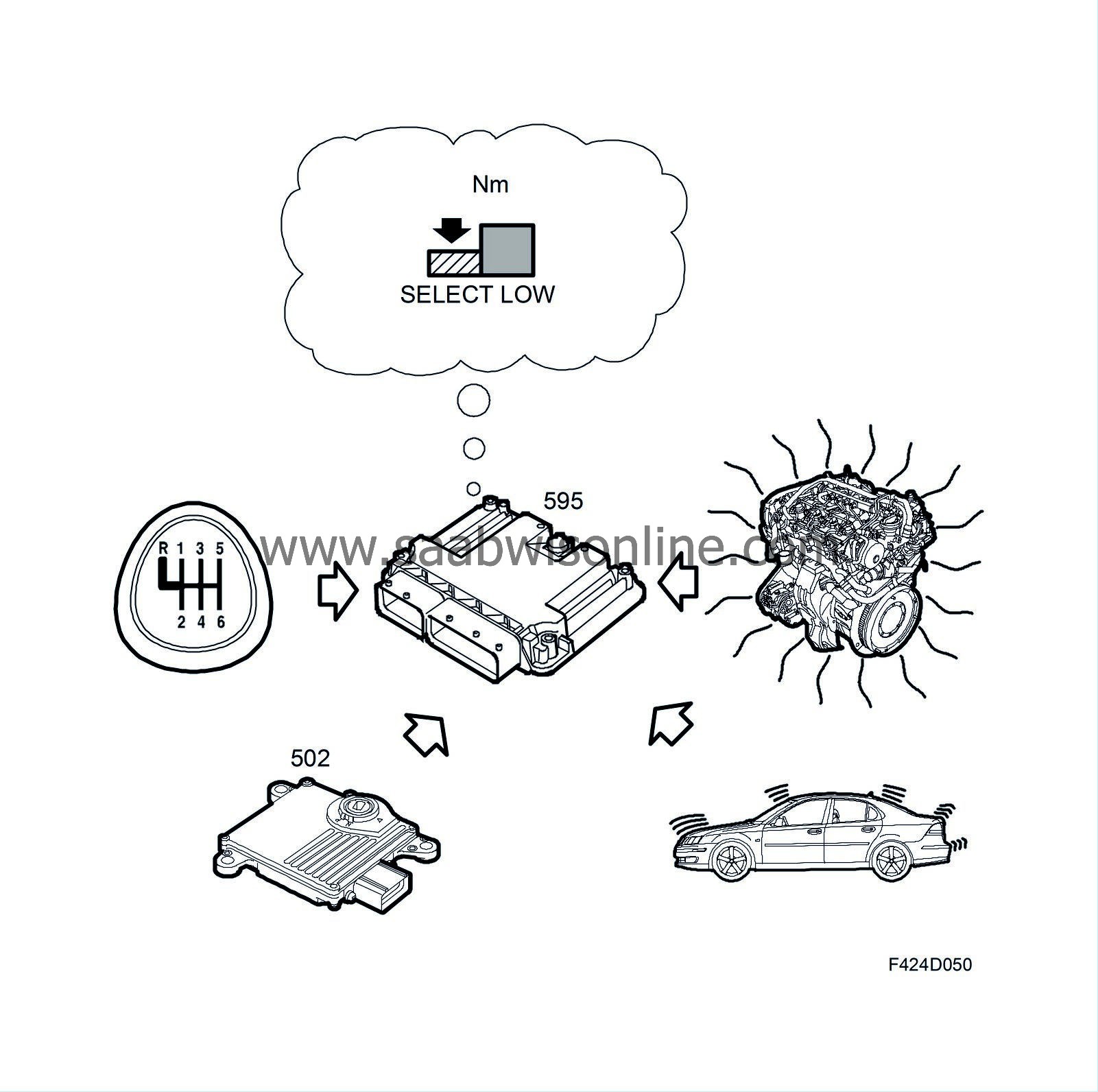
It is however not always possible to provide the requested engine torque. For example, the maximum permitted engine torque may already be reached, or the TCS/ESP system may request for a drop in torque. The following functions can limit engine torque:
| • |
TCM
|
|
| • |
Manual gearbox
|
|
| • |
Engine protection function
|
|
| • |
Active surge dampening
|
|
| • |
Brake system
|
|
| • |
Internal engine friction
|
|
These are combined to a common driving torque request. This function is used once the engine has been started. When starting the engine, a start torque request is used. The result of both of these requests is converted into a fuel quantity.
Accelerator pedal
GeneralThe accelerator pedal bracket has two built-in potentiometers. Potentiometer 1 supplies the ECM with information on driver torque request in the form of a voltage (0-5 V).
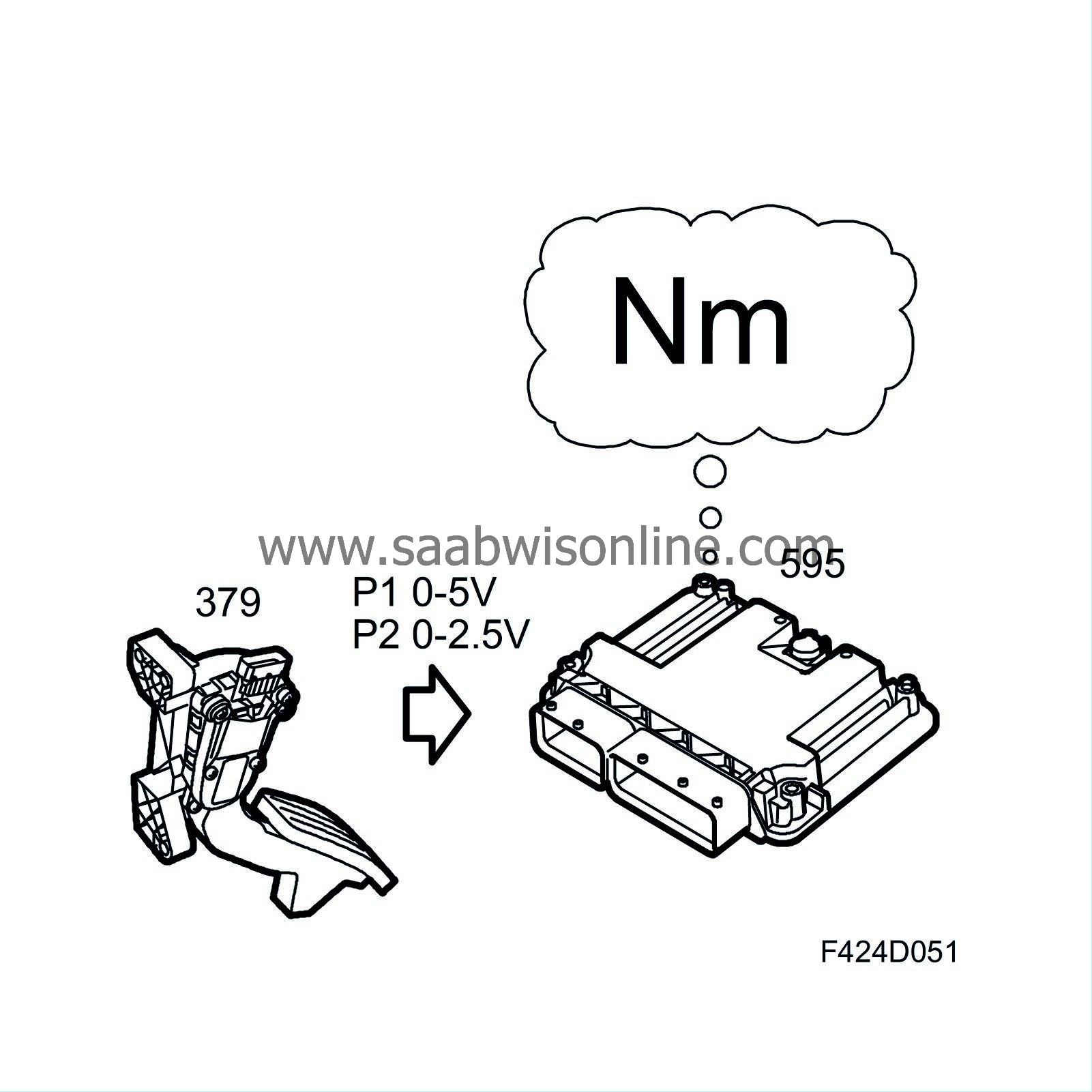
Potentiometer 2 is a safety potentiometer which provides the ECM with pedal position information in the form of a 0-2.5 V voltage. This voltage is used to check whether the information from potentiometer 1 is reliable.
Function
Potentiometer 1 provides the ECM with information about the driver's request for torque. A torque request is taken from a matrix based on pedal position and engine speed. The torque request can vary between 0 Nm (idling) and a value slightly higher than the engine's maximum permitted torque.
TCS/ESP request
If a drive wheel spins, the TCS may request for a reduction in engine torque to reduce spinning. Similarly, the ESP can request a reduction in engine torque if the car skids. The TCS and especially the ESP can request an increase in engine torque, such as to avoid skidding.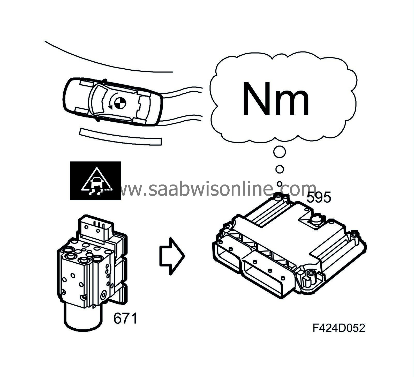
Request for A/C and generator compensation
To make engine torque independent of the current load from the A/C and generator, torque is requested to compensate for these functions. This request is always positive.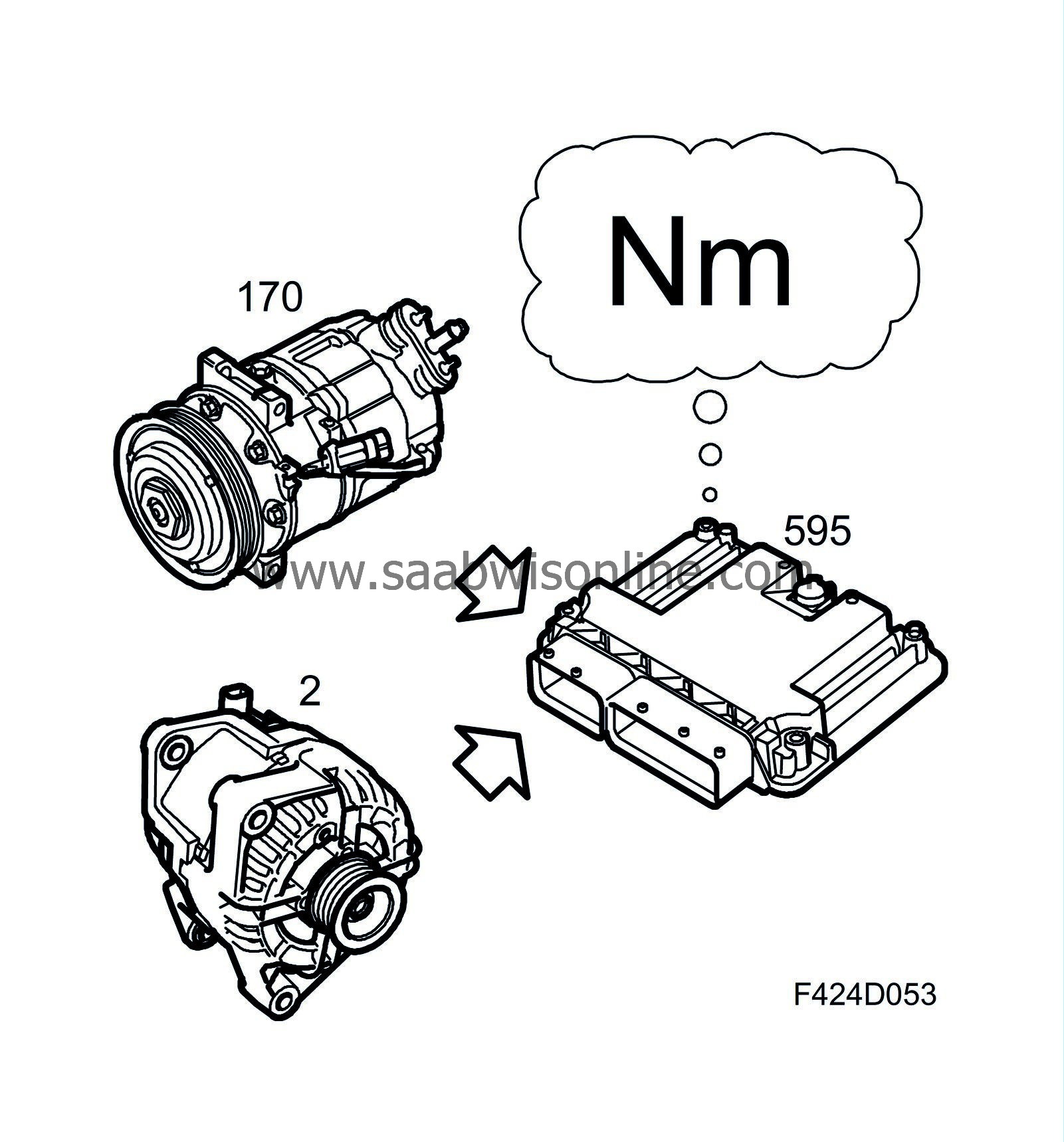
A/C compensation
The A/C compressor relay is controlled by the ECM, which also reads the current pressure in the A/C system from the pressure sensor (620). This allows the ECM to calculate the torque required to compensate for the torque used by the A/C compressor.Generator compensation
The generator notifies the ECM of the current load via a wire connected to generator connector L. This allows the ECM to calculate the torque required to compensate for the torque used by the generator.
Idle speed control
The purpose of idle control is to reach a suitable balance between the torque produced by the engine and the torque required to keep the engine and auxiliaries running. The nominal idling speed is 850 rpm for a warm motor.Function
At idling speeds above the nominal value, there is an excess of engine torque. The idling function request a lower torque until the nominal idling speed is reached. If the idling speed is lower than the nominal value, there is a torque deficiency. To achieve the nominal idling speed requires an increase in engine torque.
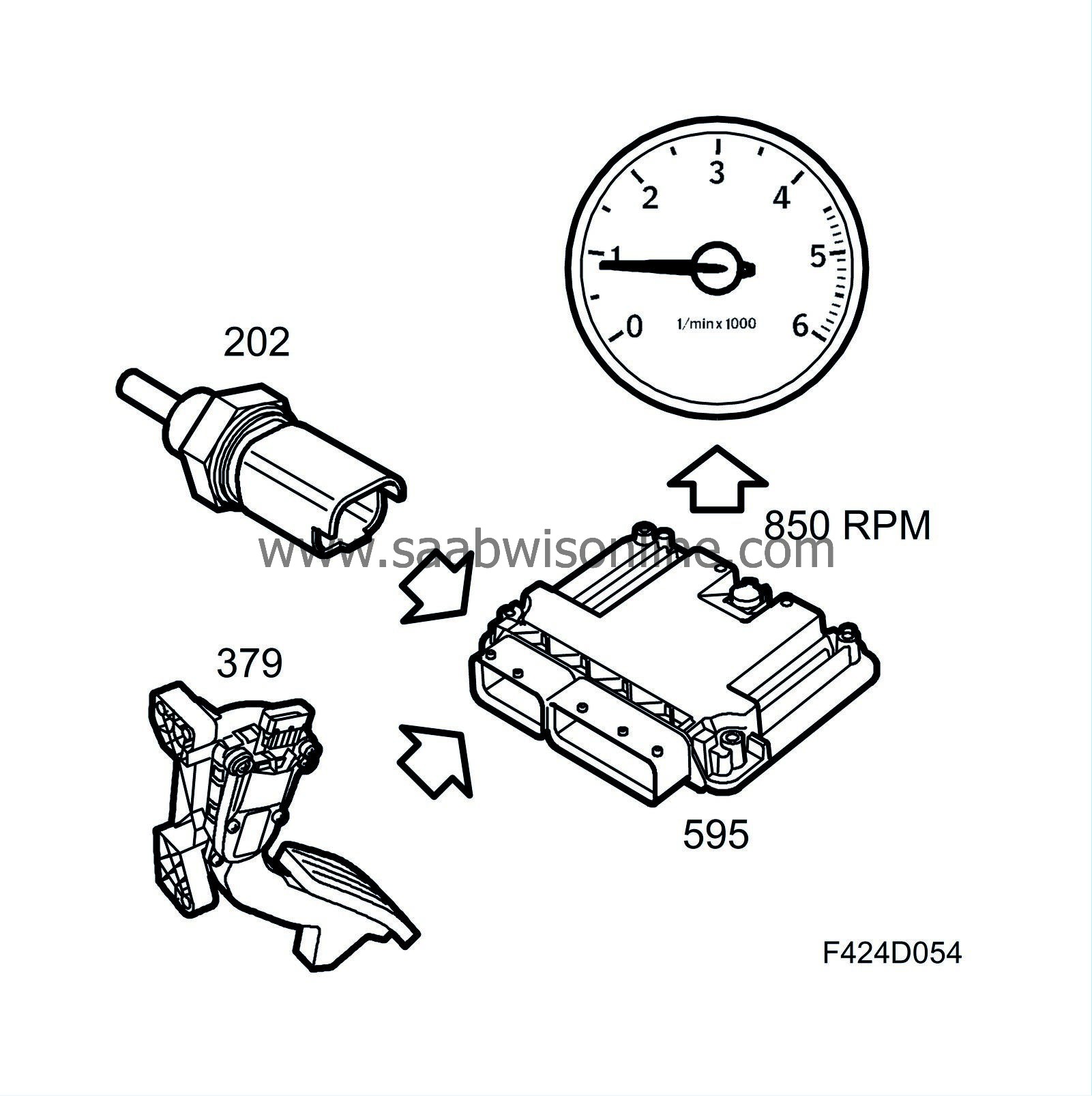
The nominal idling speed depends on the coolant temperature. A cold engine has a higher idling speed.
Idle speed control is active when the accelerator is not depressed.
Active surge dampening
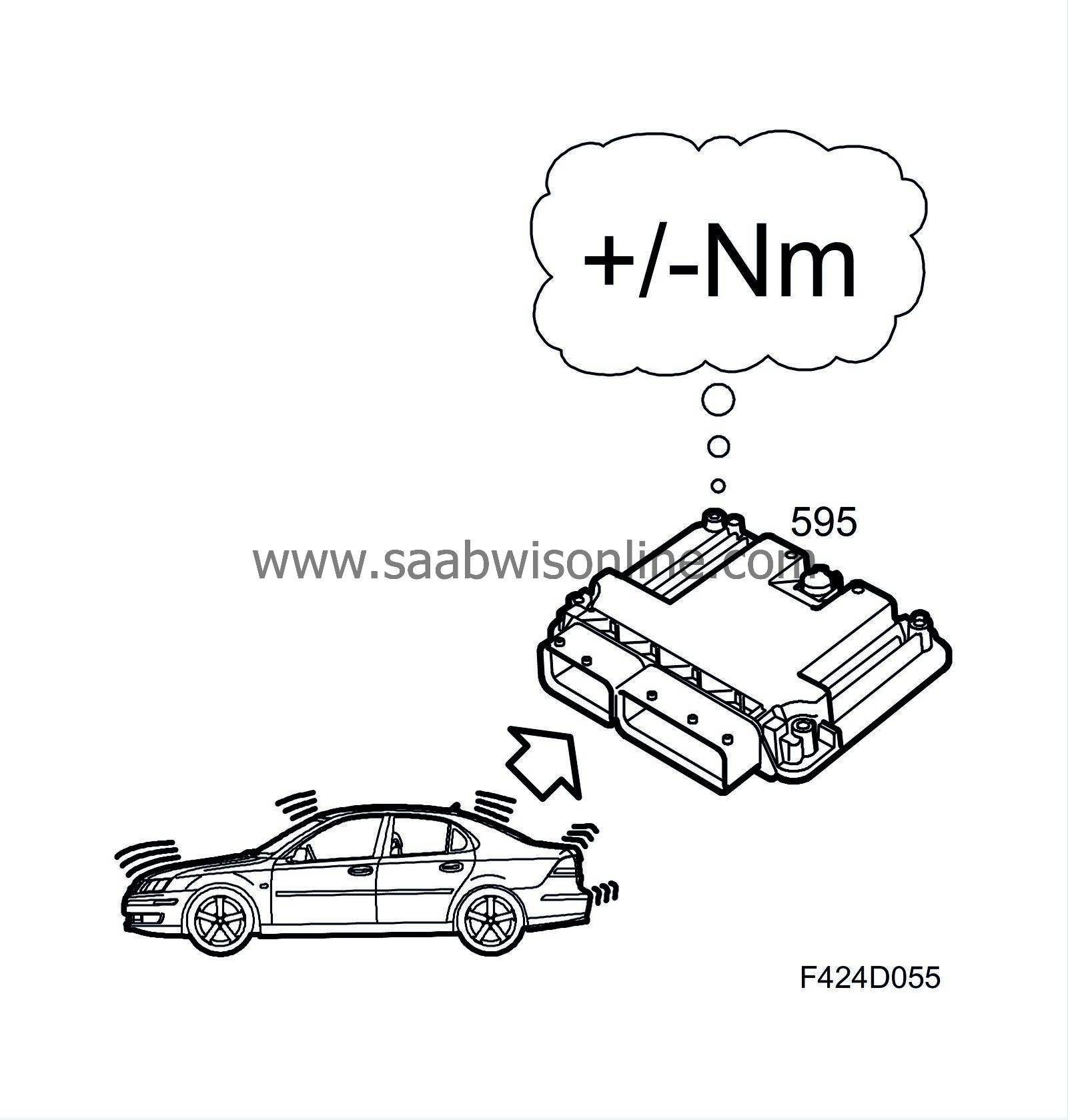
Surges (fluctuations) may be experienced during acceleration/deceleration. They are caused by sudden increases in engine torque in conjunction with a certain amount of elasticity in the power train and engine mounting.Function
The anti-surge function detects fluctuations in engine speed and dampens these by requesting and increase or decrease in torque. This reduces or eliminates the surges.
Internal engine friction
The engine itself requires a certain amount of torque due to internal friction and pump losses. To compensate for this, this function normally sends a request for torque.Function
The engine's own torque consumption is calculated from:
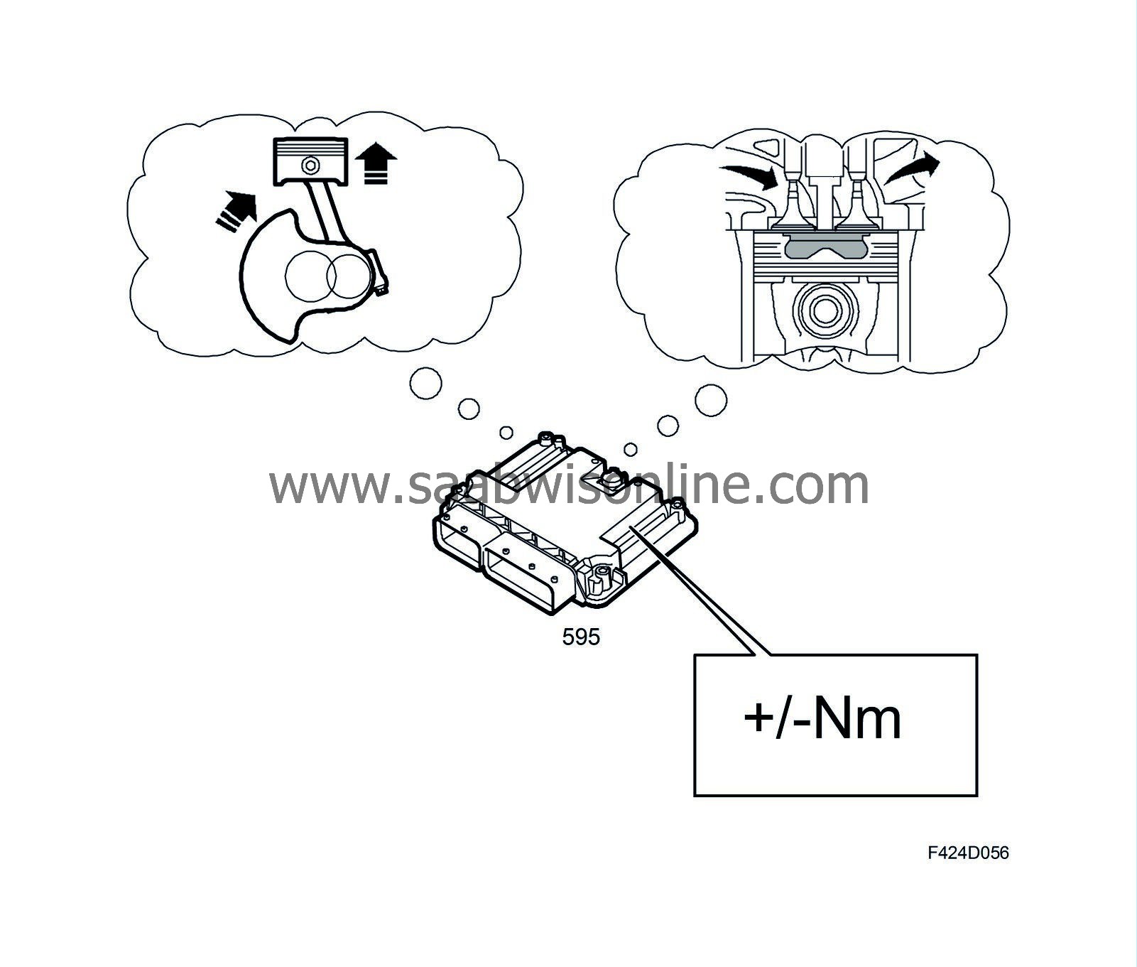
| • |
Coolant temperature
|
|
| • |
Oil temperature
|
|
| • |
Engine speed
|
|
| • |
Pressure drop over the particle trap
|
|
| • |
Calculated exhaust mass flow
|
|
The first three points relate to engine friction and the last two to pump losses.
TCM engine torque limitation
To improve gearchange quality, engine torque must sometimes be limited. In certain cases, torque is also limited for safety and durability reasons.Function
The TCM determines the maximum engine torque that is permitted. During gear changing, the engine torque is generally reduced slightly to ensure good shift quality. The torque is also limited for durability reasons. To protect the gearbox during stalling, the TCM sends the limit for permitted torque over the bus.
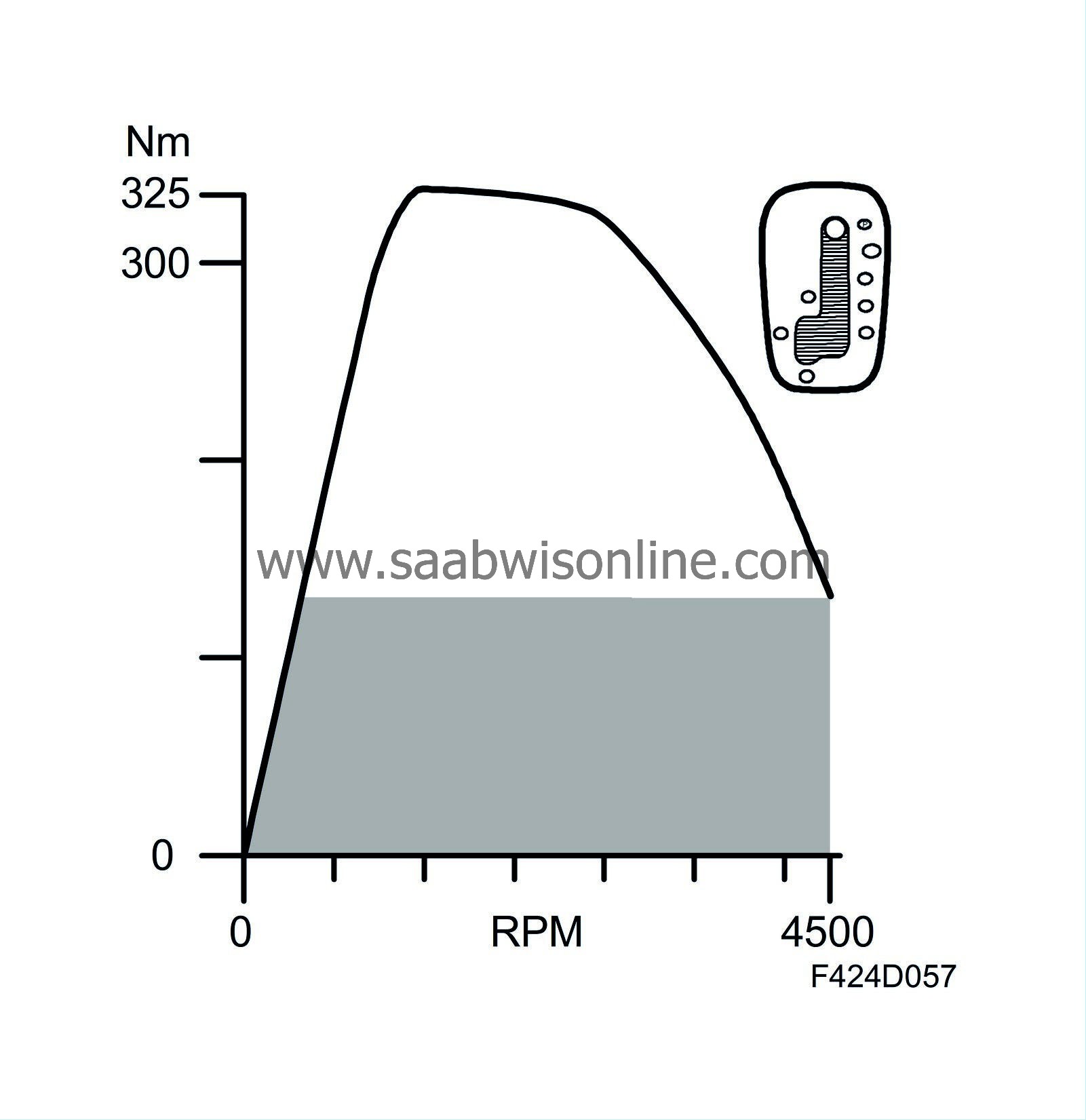
Torque limitation, manual gearbox
The engine torque is limited when reverse gear is engaged.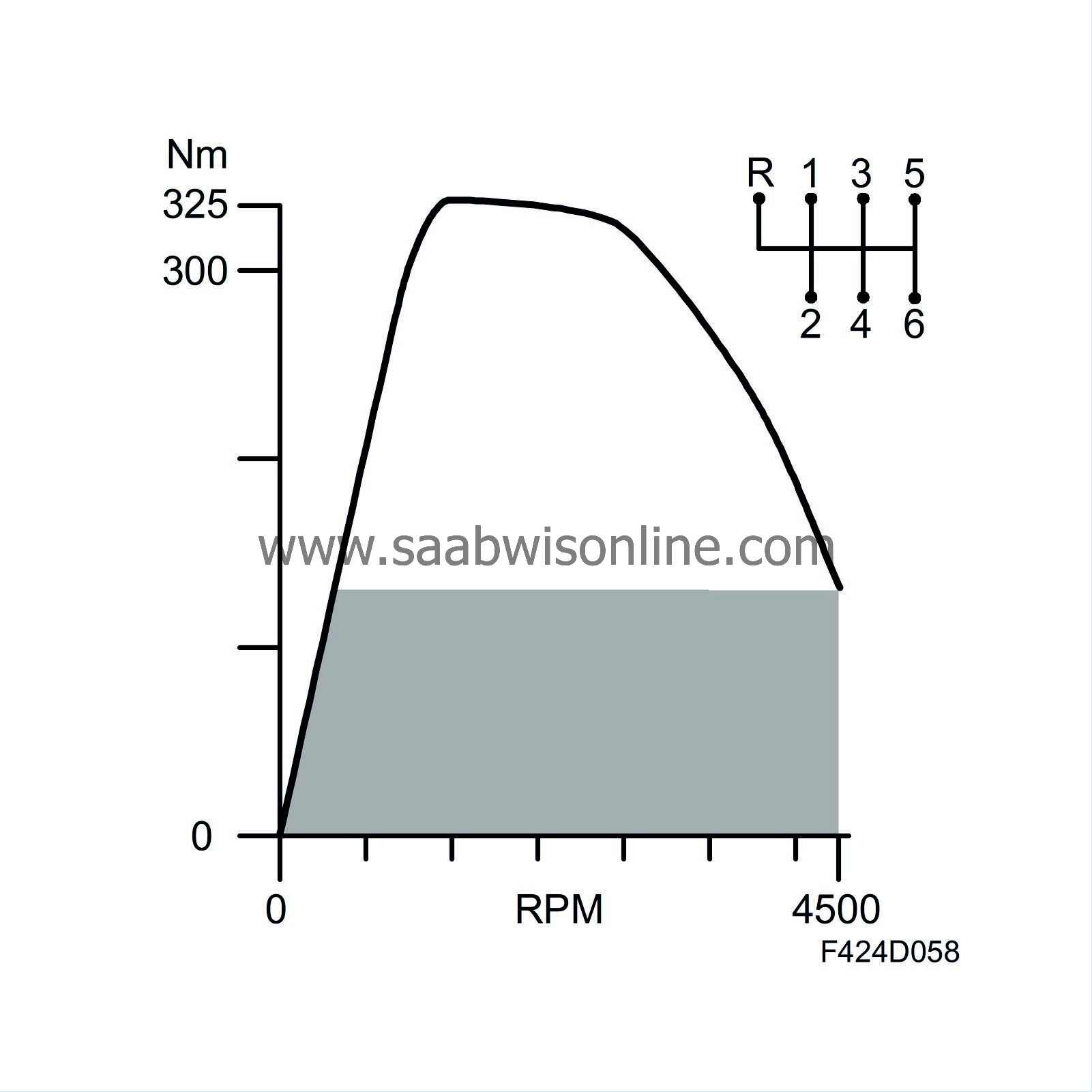
Torque limitation, braking
The maximum permitted torque must, for durability reasons, be limited when the brakes are applied.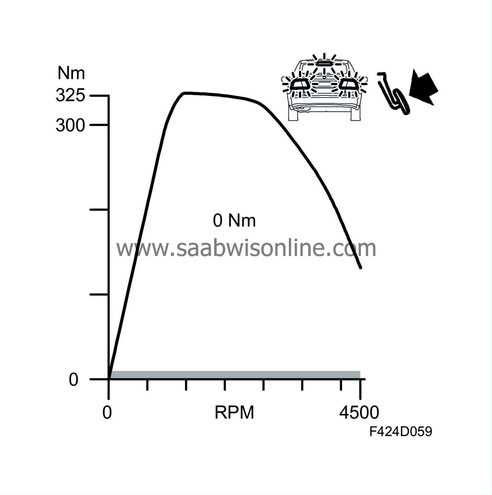
| Fuel |

The requested engine torque is converted to a requested injection period, injection timing and fuel pressure for the four fuel injectors.
To start with, the requested engine torque must be converted to a fuel mass.
Injection duration
Conversion of engine torque to fuel quantityThe ECM uses matrices and tables to calculate the fuel mass that corresponds to the requested engine torque. By measuring the temperature of the fuel, the ECM compensates for the difference in density between warm and cold fuel.

The value produced is the fuel mass per combustion to be supplied to the engine. This value is converted from fuel mass to fuel quantity (volume).
This value is then transferred to the cylinder balancing function, which adjusts the fuel quantity.
Cylinder balancing
GeneralThe purpose of the cylinder balancing function is to balance the combustion pulses from each cylinder, so that the engine runs smoothly and to reduce vibrations. The function adds or subtracts a quantity from the fuel quantity.
Function
During idling, when the injected quantity of fuel is relatively small, the function is used to compensate for the different quantities injected into each cylinder and the efficiency of each cylinder. At speeds above idling, compensation is mainly performed due to the different efficiencies of each cylinder. The injected quantity is calculated and adjusted individually for each cylinder.
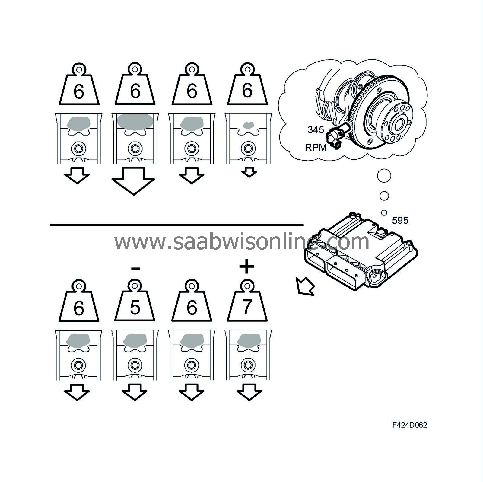
The ECM monitors the movement of the crankshaft. If, for example, the crankshaft accelerates significantly when cylinder 2 fires, the fuel quantity to this cylinder needs to be reduced. A compensated quantity is calculated before the cylinder fires the next time. The quantity is adjusted so that the cylinder produces the same work pulse as the other cylinders.
The total value is sent to the smoke limitation function.
Smoke limitation
GeneralThe purpose of the smoke limitation function is to determine the maximum fuel quantity that can be injected without exceeding the smoke limit. Smoke limitation operates when there is insufficient air for smoke-free combustion.
Function
The maximum fuel quantity that can be injected without exceeding the smoke limit is calculated based on the engine speed and air mass per combustion. This value acts as an upper limit for fuel quantity that can be injected.
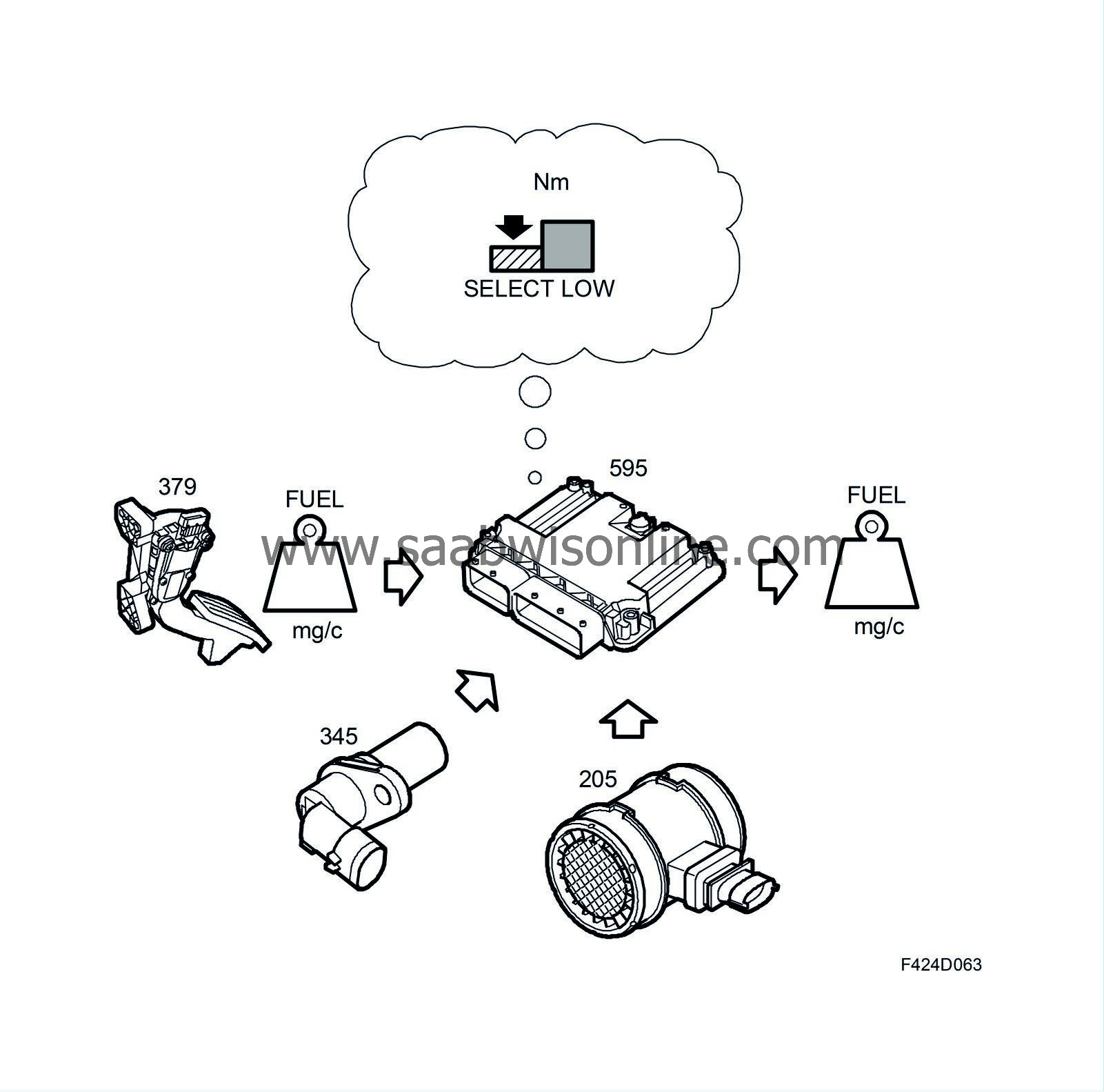
If the fuel quantity following conversion from engine torque exceeds the smoke limitation function's quantity, the fuel quantity will be limited. This also limits engine torque. The value is sent to the cut-off function.
Cut-off function
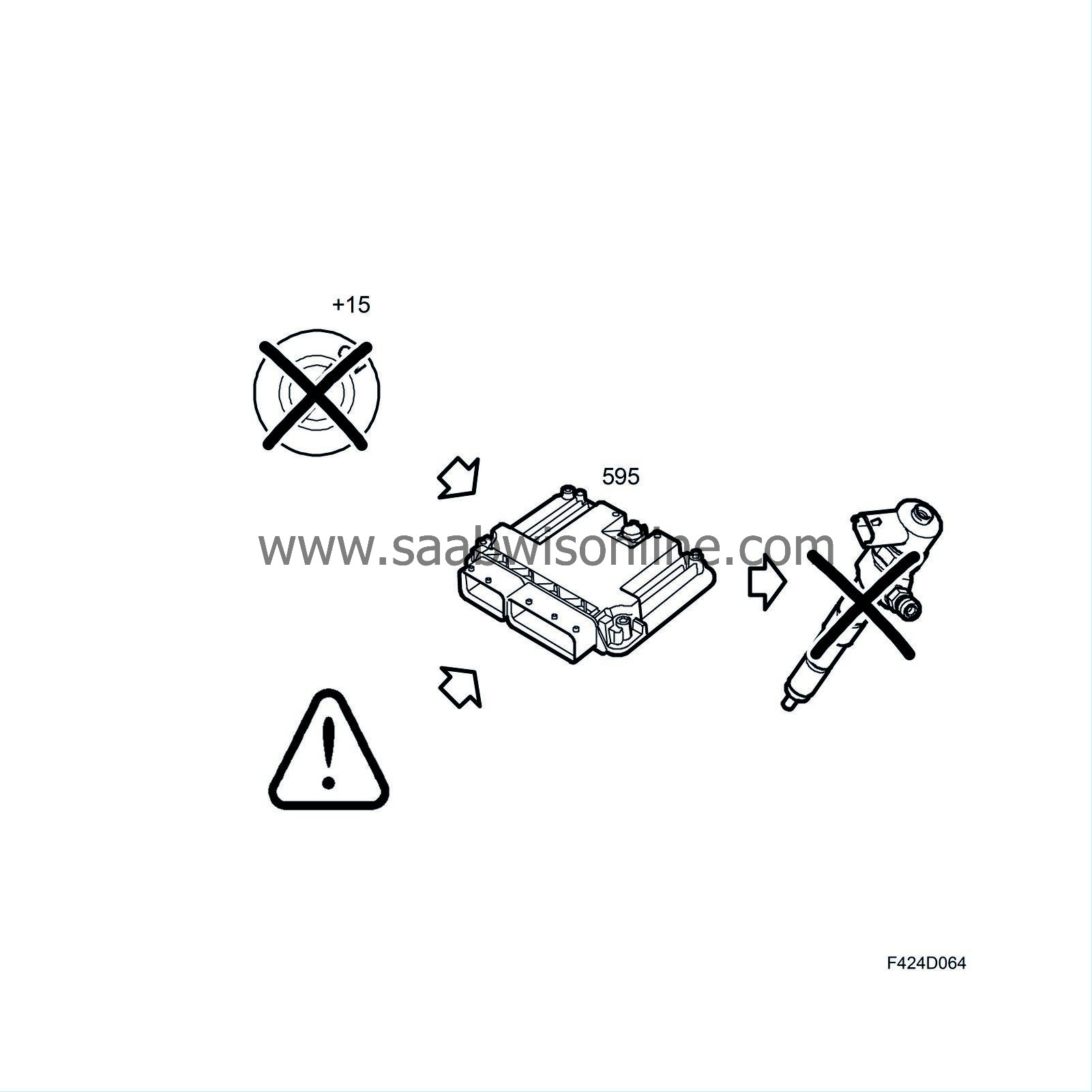
GeneralThis function can set fuel quantity to 0, which means that the engine will stop. This is done if +15 is not present or if one of certain critical faults arises. During normal operation, this function merely sends the fuel quantity value on for calculating the injection period.
Injection
Injection period, basic periodThe fuel volume per combustion is converted into a period for which the injector must stay open. This depends on the injector's flow and the current differential pressure.
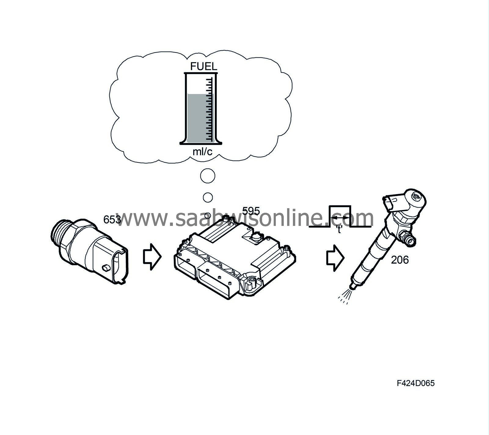
The pressure in the fuel rail is measured by the fuel pressure sensor (653).
Request for injection from other functions
Injection can also be requested by the pilot injection function and particle trap regeneration function.
Pilot injection
To reduce engine noise, so-called diesel knock, at low coolant temperatures, pilot injection is used. This means that a small quantity of fuel is injected just before the main injection. The function is active when the coolant temperature is below +60°C. The function is deactivated at high engine speeds.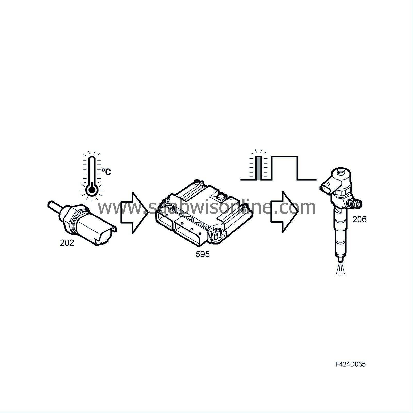
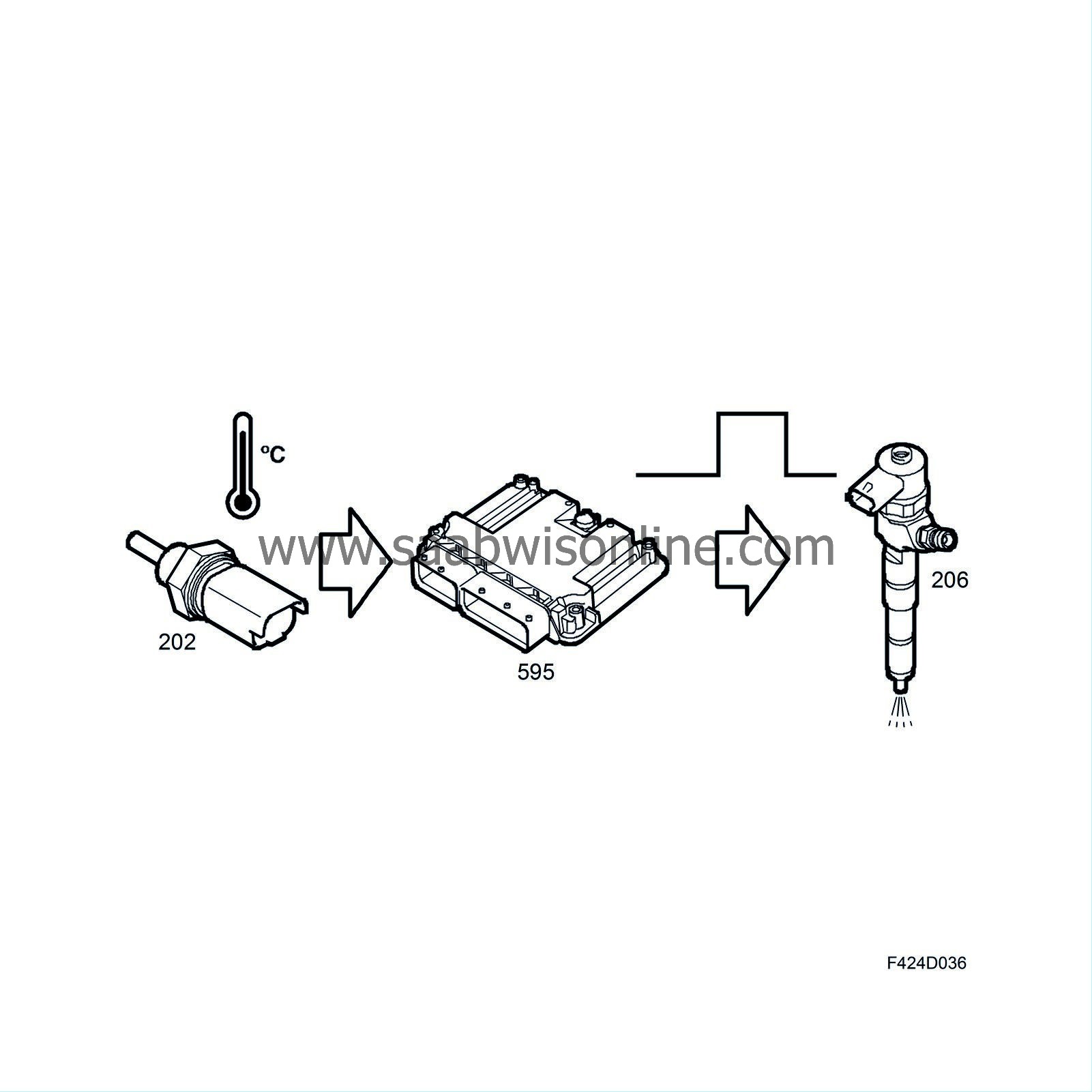
Diesel knock arises when the injected fuel ignites rapidly. The duration between the fuel being injected into the combustion chamber and it igniting is known as the injection delay. Theoretically, we want to keep this delay as short as possible. The delay depends on the fuel's cetane rating, the cylinder temperature and how well the fuel is injected. A long delay means that a relatively large amount of fuel enters the cylinder prior to ignition. This causes a violent increase in pressure that leads to very noisy, rough running.
Fuel with a high cetane rating can shorten the ignition delay, as too a high combustion chamber temperature. Good dispersion of the fuel is achieved through a combination of injector design and high fuel pressure.
When the engine is cold, the heat losses in the cylinder to the surroundings are great. This means that the temperature of the air on injection is relatively low. This causes a long injection delay, which produces more diesel knock.
Injecting a small quantity of fuel just before the main injection raises the temperature in the combustion chamber significantly. This means that the injection delay for the main injection is short and thus reduces engine noise.
Particle trap regeneration
When the particle trap is regenerated, the temperature in the trap must climb to at least +550°C to burn off the soot. Roughly 160 degrees after top dead centre, a small amount of fuel is injected into the cylinder. Since this fuel is injected late (the piston has almost reached bottom dead centre and the exhaust valve is open), this fuel does not increase engine torque in any way. Nor does this increase the temperature of the exhaust gas significantly. The exhaust gas is quite simply enriched in hydrocarbons (HC). This starts a reaction in the front catalytic converter, raising the temperature. When these hot gases reach the particle trap, they will react with the catalytic converter in the trap raising the temperature further. This burns off the soot in the particle trap.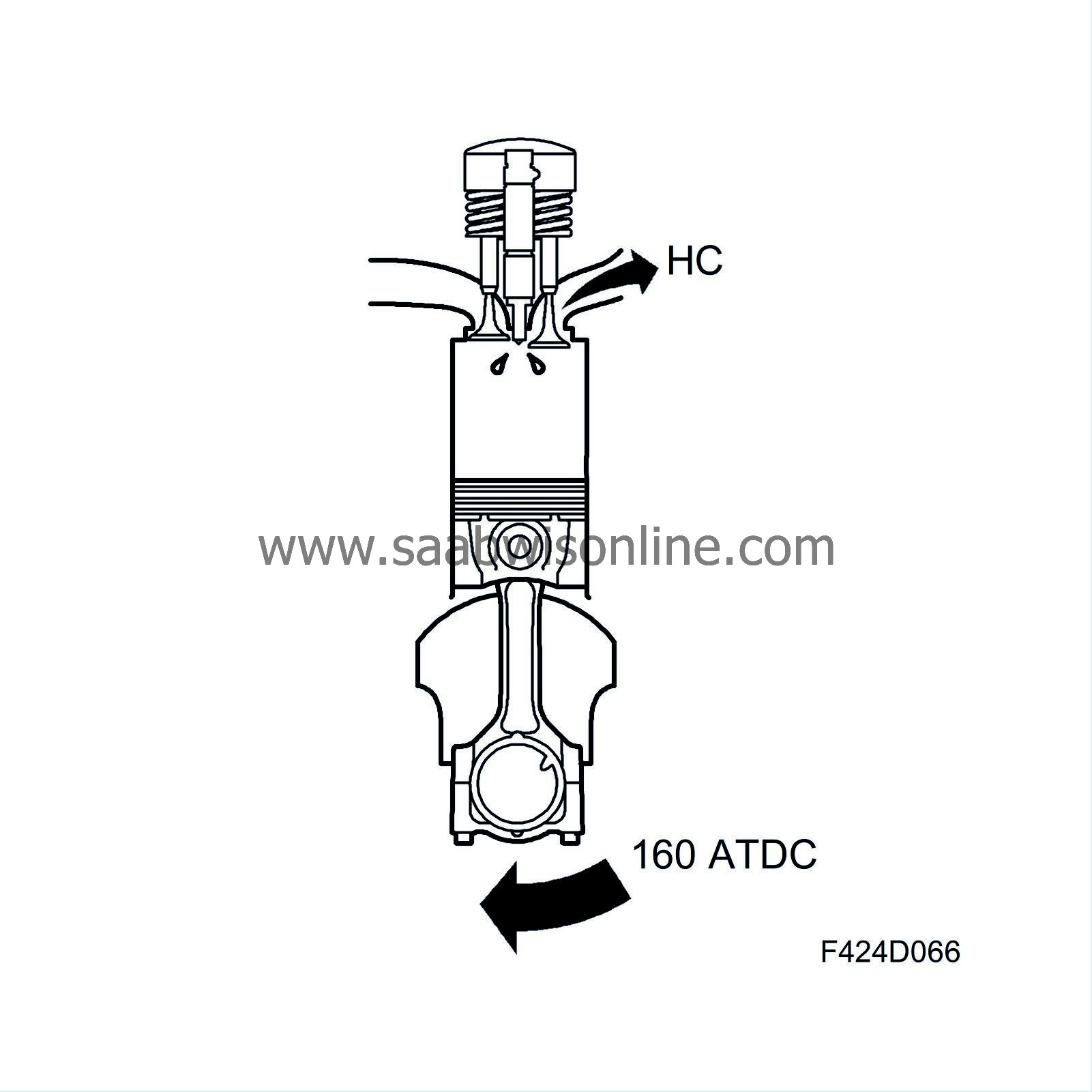
Compensation for injector delay
Compensation must be made for the time from the power amplifier in the ECM being activated to the injector opening and fuel being injected.
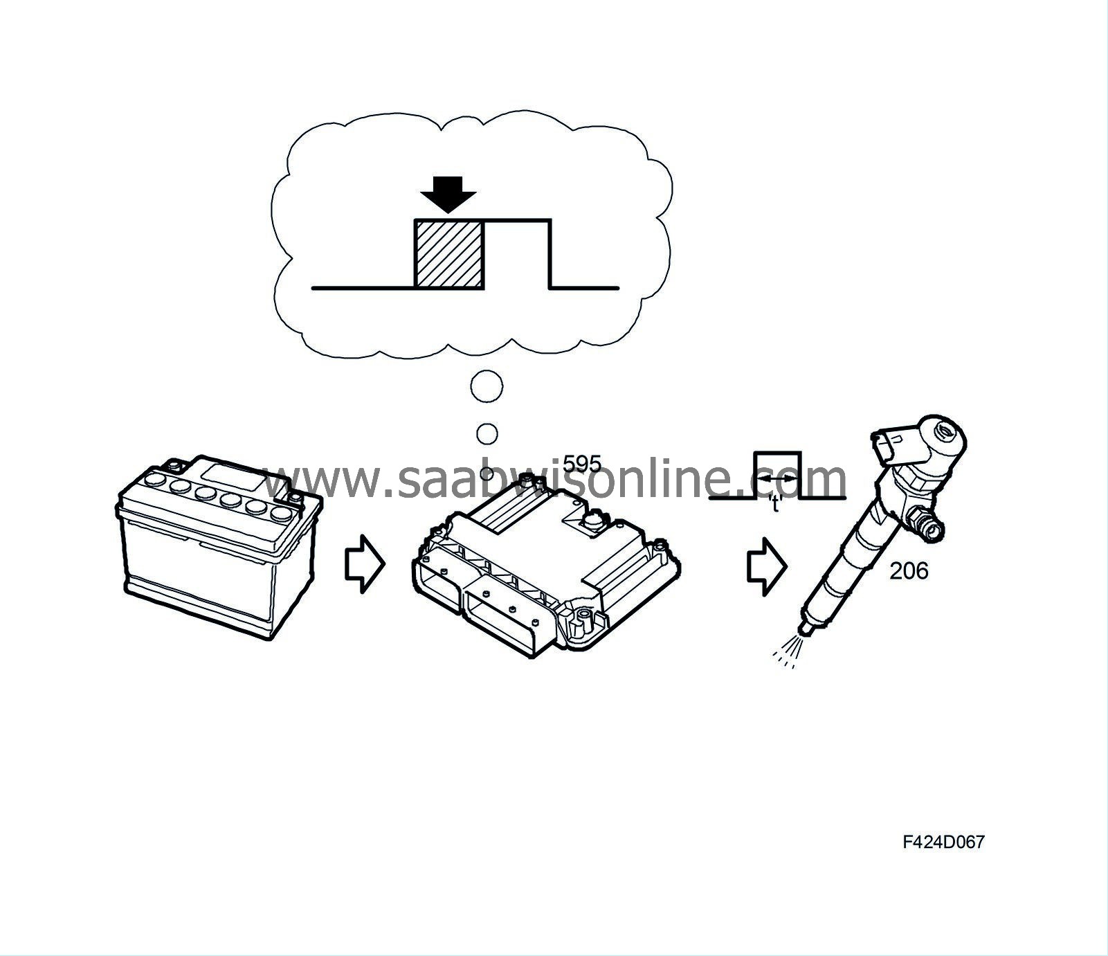
This delay time depends on the system voltage.
Pressure wave compensation
When the injectors open, a pressure wave forms in the connection pipe and fuel rail. The ECM must compensate for this phenomenon, otherwise an incorrect quantity of fuel will be injected.

Compensation is individual for each cylinder and primarily depends on fuel pressure and temperature.
Injector activation
The ECM activates each injector at the calculated point in time. The injector is kept open for the injection period that has been calculated.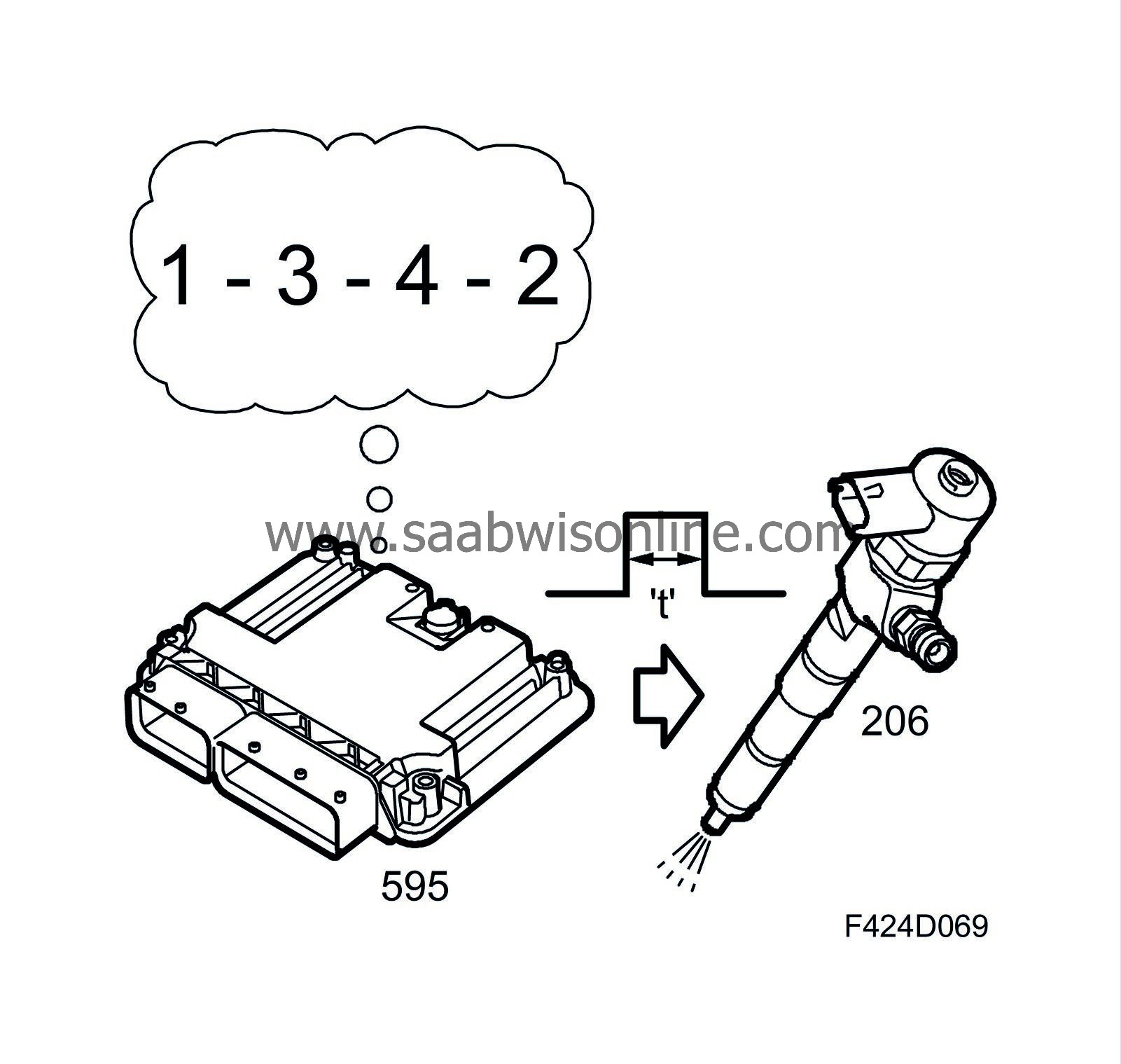
Injection timing
The moment of injection depends on the engine speed and load. The purpose of this control is to ensure combustion pressure builds up correctly.
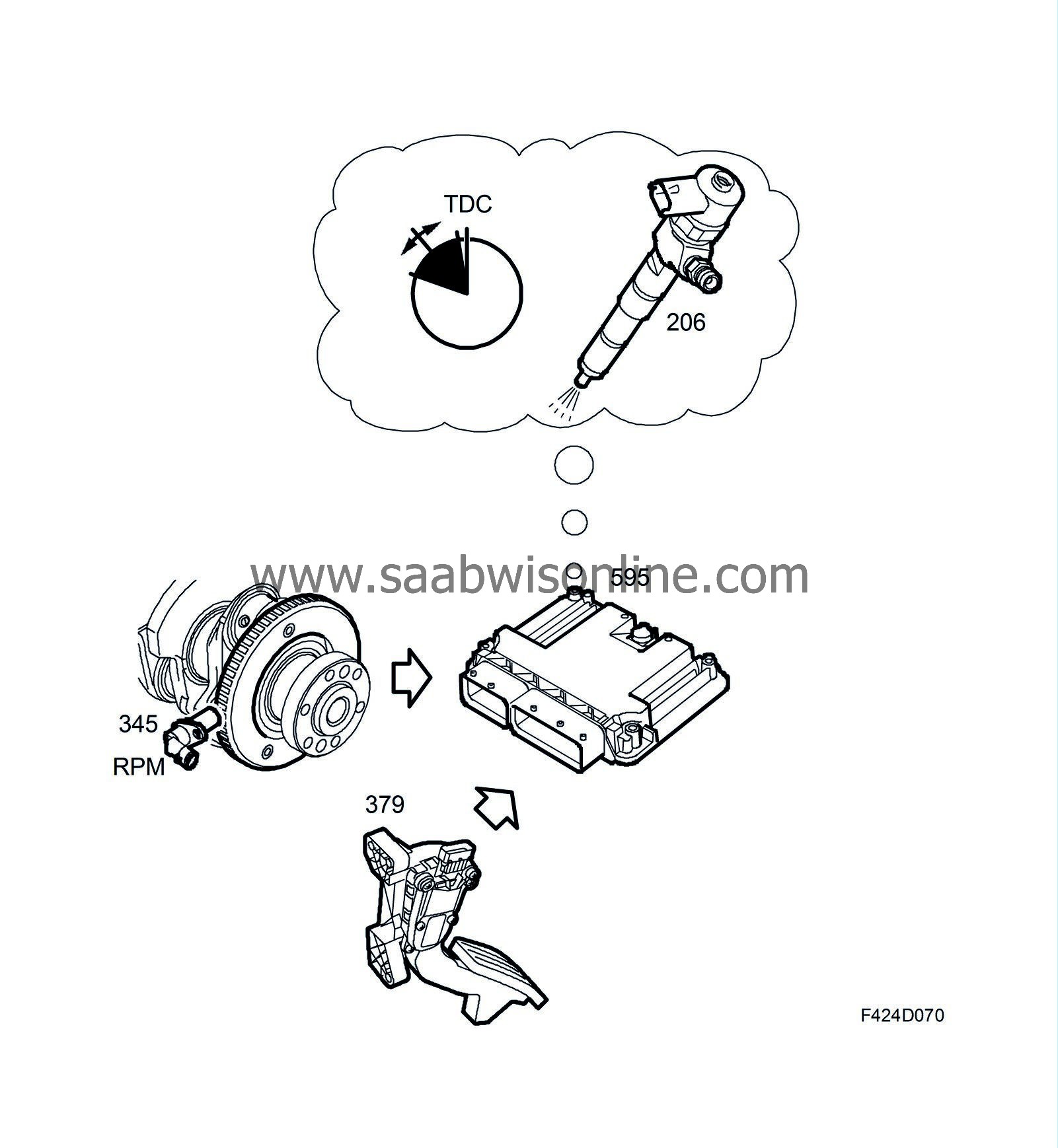
The injection timing specifies the injection duration in camshaft degrees, and should not be confused with the injection period.
Fuel pressure
GeneralThe fuel pressure depends on the prevailing operating conditions and varies between roughly 30 MPa and 160 MPa (300-1600 bar). The pressure is controlled by two valves: one on the high-pressure pump and one on the fuel rail. That the requested pressure has been achieved is monitored by the ECM with the aid of the fuel pressure sensor on the fuel rail.

General function
As the engine's fuel requirements change over a large range, the fuel pressure supplied by the high-pressure pump to the fuel rail must be regulated.Calculation of fuel consumption, general
The volume is accumulated for each combustion and the value sent on the bus. The main instrument unit uses the value to correct the tank gauge and the information display uses it to calculate the fuel consumption.
| Air |
General
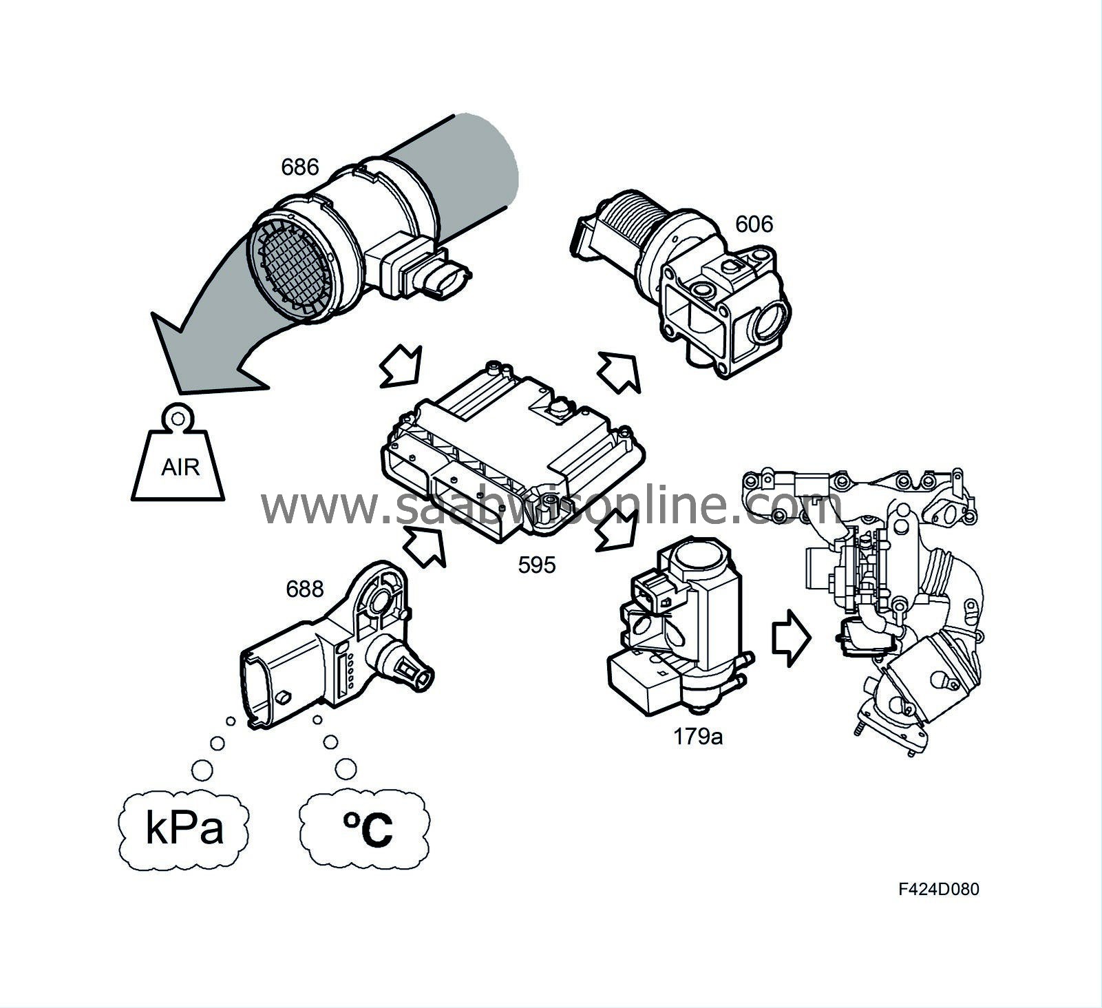
The purpose of the function is to coordinate the engine's air requirement. The following primary sensors are used:
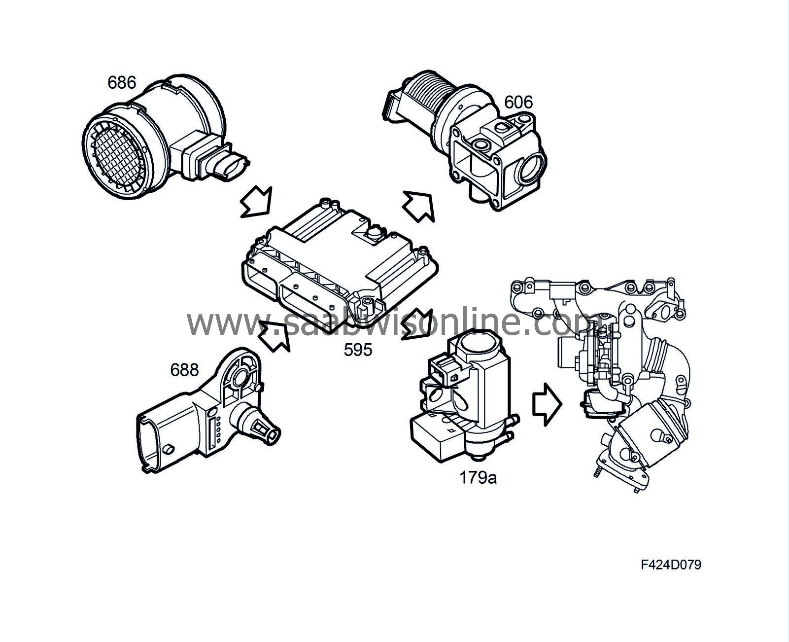
| • |
mass air flow sensor unit (686) to measure the mass and temperature of intake air
|
|
| • |
intake air sensor (688) to measure the pressure and temperature of the charge air
|
|
The ECM uses the following actuators to control the engine's air change rate:
| • |
boost pressure control valve (179a)
|
|
| • |
EGR valve (606)
|
|
Calculation of air mass requirement
The function calculates the mass of air per combustion that is required at that moment in time. This is primarily based on the fuel request and engine speed.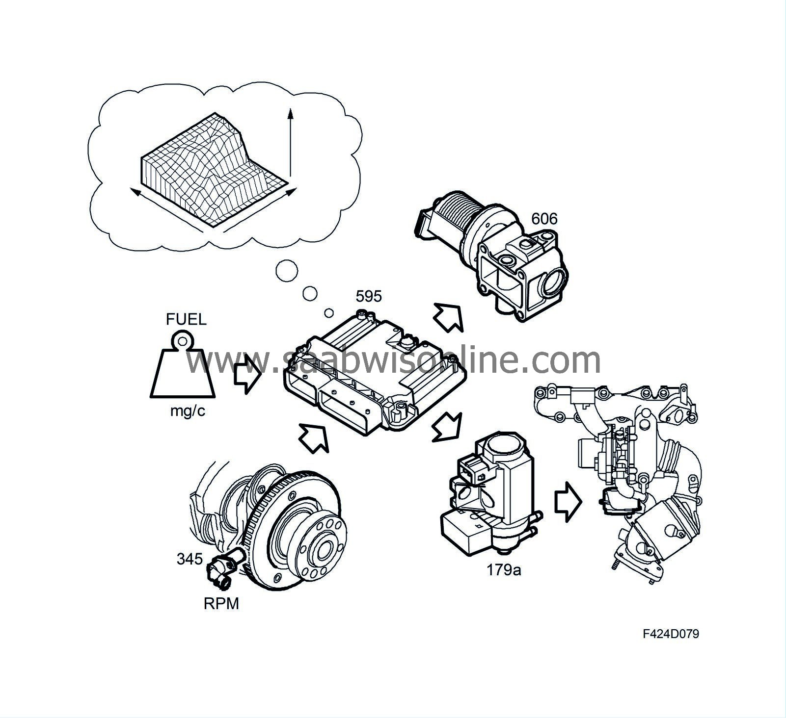
Control of air mass requirement
Once the air mass per combustion required for the given fuel quantity has been calculated, the ECM has two ways of executing the request: turbo control and EGR control.Engine aspiration is increased using turbo control. Increased boost pressure raises the air mass in the engine. The EGR function works in the reverse; it replaces air mass with exhaust gases. The ECM measures the current aim mass using the mass air flow sensor (205). This is converted to air mass per combustion. The value is compared to the requested value. If the values differ, the air supply is corrected using turbo control and EGR control. The value from the mass air flow sensor is corrected for the inertia of the air in the intake system, i.e. pipes and charge air cooler.
Turbo control
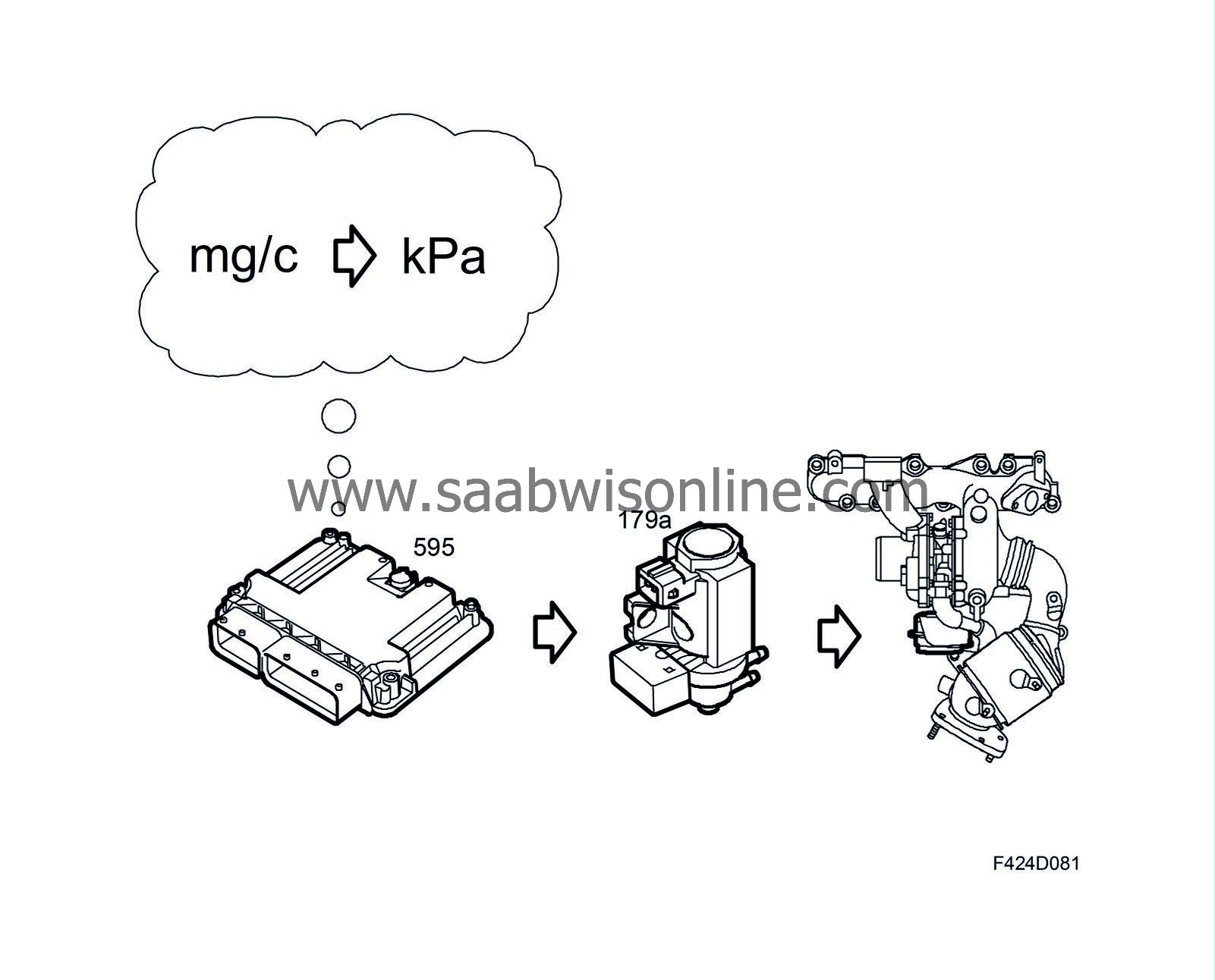
The requested air mass per combustion is achieved by controlling the boost pressure.The ECM calculates the boost pressure (desired value) that is required to obtain the requested air mass per combustion. The desired value is primarily based on the following parameters:
| • |
engine speed
|
|
| • |
fuel quantity
|
|
| • |
current boost pressure
|
|
The result is a PWM signal that controls the boost pressure control valve (179a). This valve controls the vacuum to the turbocharger's vane regulator. The ECM compares the current boost pressure and, if necessary, corrects the PWM signal. Turbo control is adaptive.
EGR control
EGR control affects the air mass per combustion. See
| Glow heating |
General
The main purpose of the glow heating function is to preheat the combustion chamber to quickly and safely start the engine at slow low temperatures as possible. Glow heating can also be activated in conjunction with particle trap regeneration. The glow heating function has five sub-functions.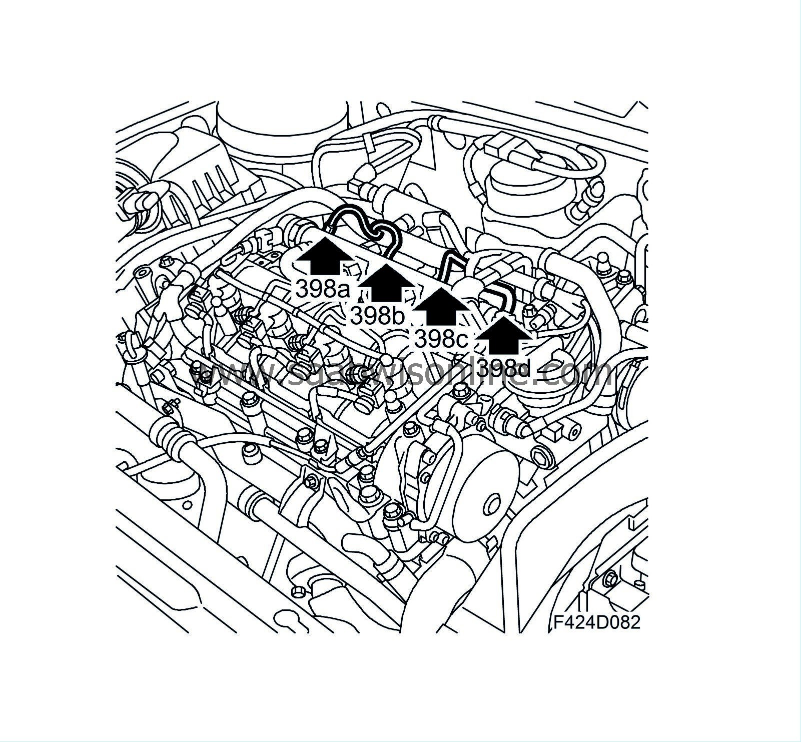
| • |
Preheating
|
|
| • |
Starting preparation heating
|
|
| • |
Starter heating
|
|
| • |
After-heating
|
|
| • |
Intermediate heating
|
|
Fuel ignition requires sufficient heat from compression. When starting a cold engine, compression leakage and thermal losses are greater than when starting a warm engine. This may mean that the fuel does not reach flash point and that the engine does not start.
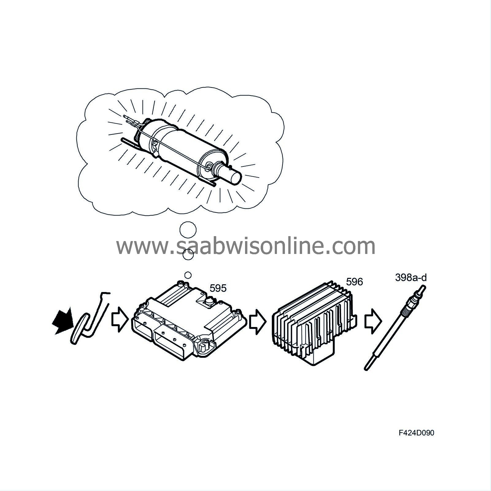
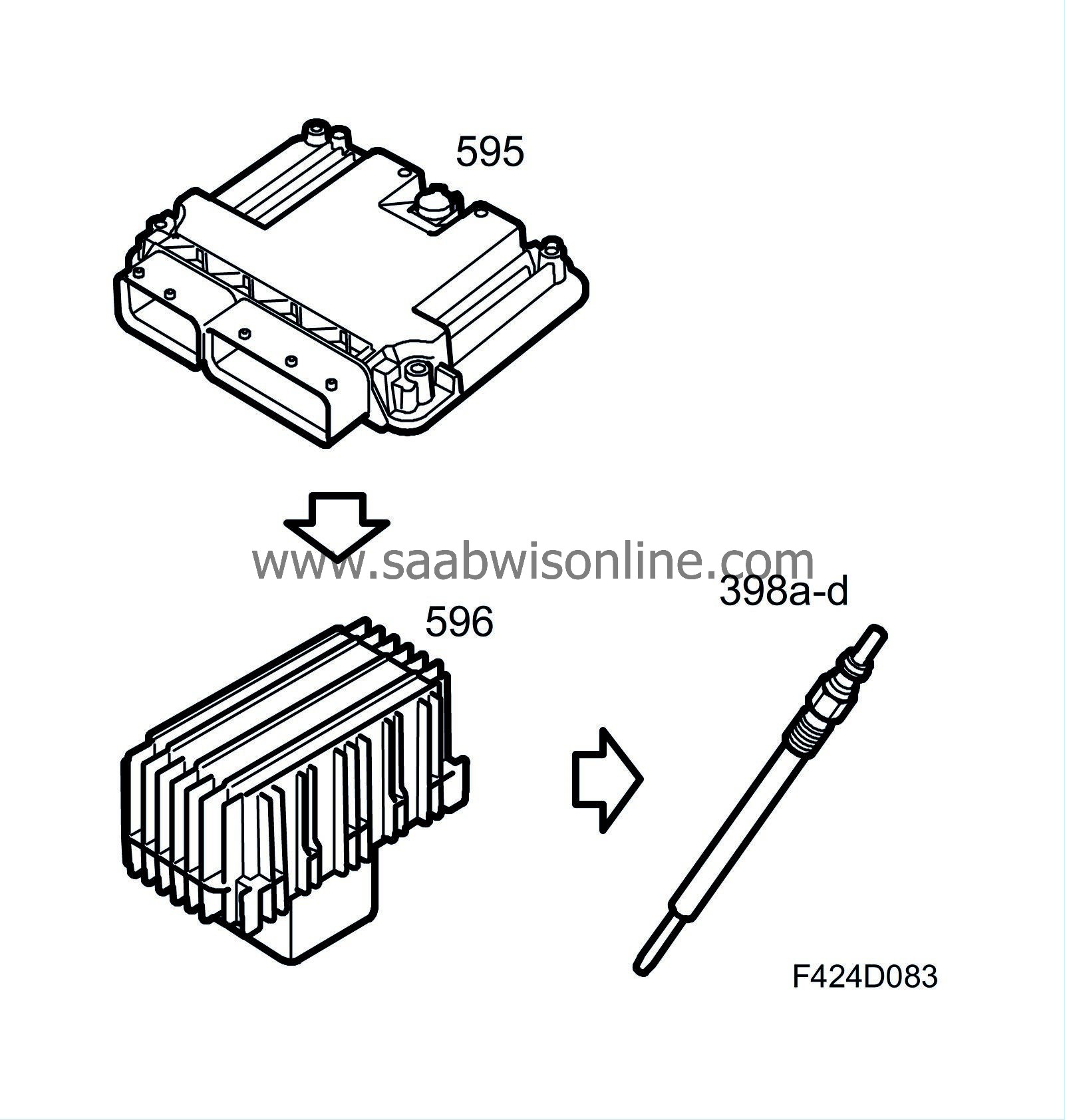
Each cylinder head has a glow plug (398). When the glow function is activated, the glow plugs heat up, in particular its tip which protrudes into the combustion chamber. This means that the fuel becomes sufficiently hot for ignition. Since the current consumption of the glow plugs is very high, these are controlled by the ECM via the glow plug control module (596).
To increase the engine load during regeneration, the glow plugs may be activated. Their power consumption increases the load on the generator, which in turn requires more engine torque. The ECM will compensate for the increased torque by increasing the fuel quantity that is injected. The result is hotter exhaust gases and increased exhaust gas flow through the particle filter.
Preheating
Preheating starts when the ignition key is turned ON. The duration of preheating varies depending on the coolant temperature. If the engine is already warm, the glow duration is 0. Information on glow plug activation is also sent of the P-bus and read by the MIU. This then turns on the glow plug indicator lamp.
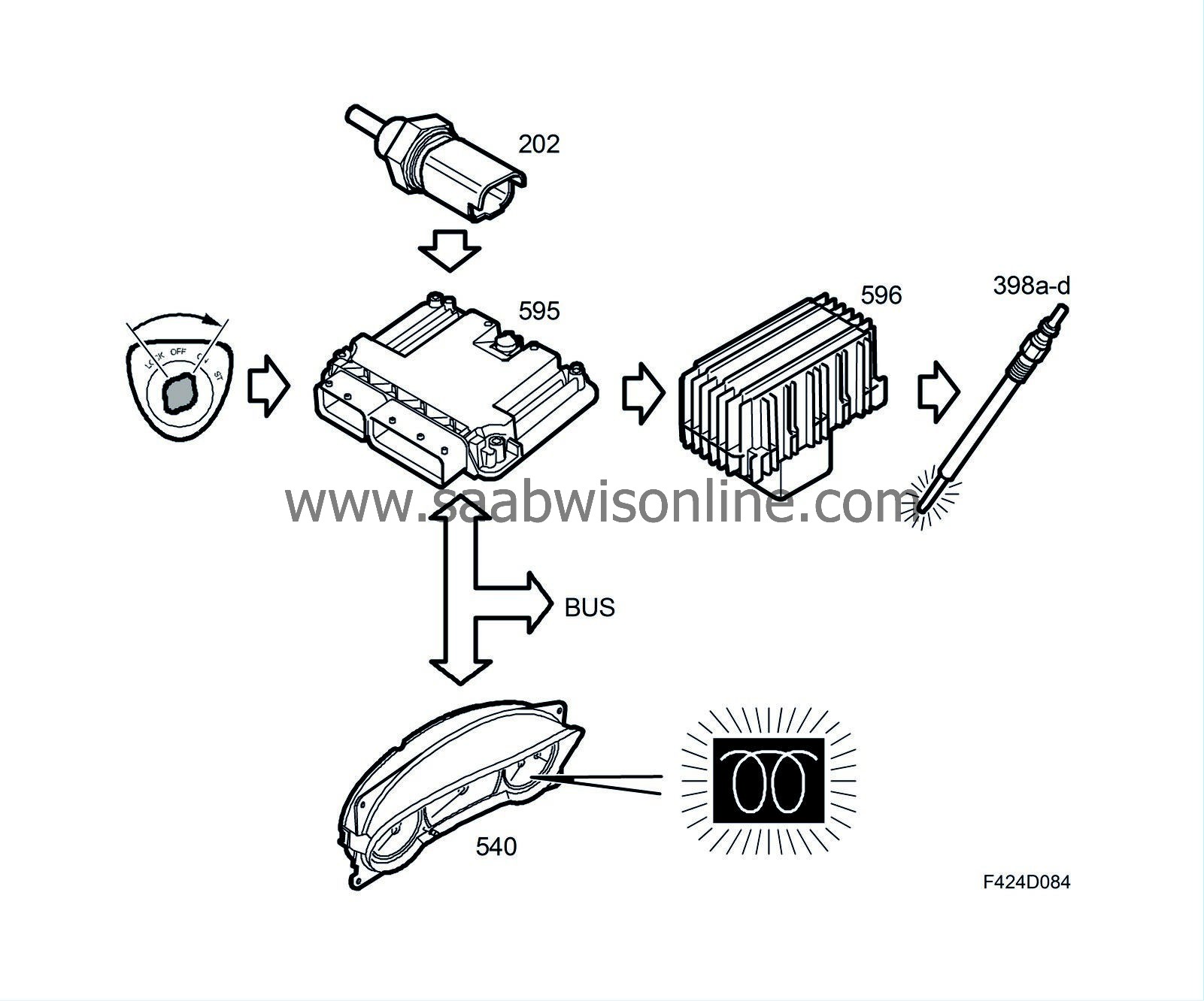
Preheating is turned off after a period and replaced by start readiness glow. If the engine has been started it is replaced by starting glow.
Starting preparation heating
Start readiness glow starts once preheating is finished. Its purpose is to keep the glow plugs warm awaiting starting. Start readiness glow is switched off after a certain period. If the engine is started it is replaced by starting glow.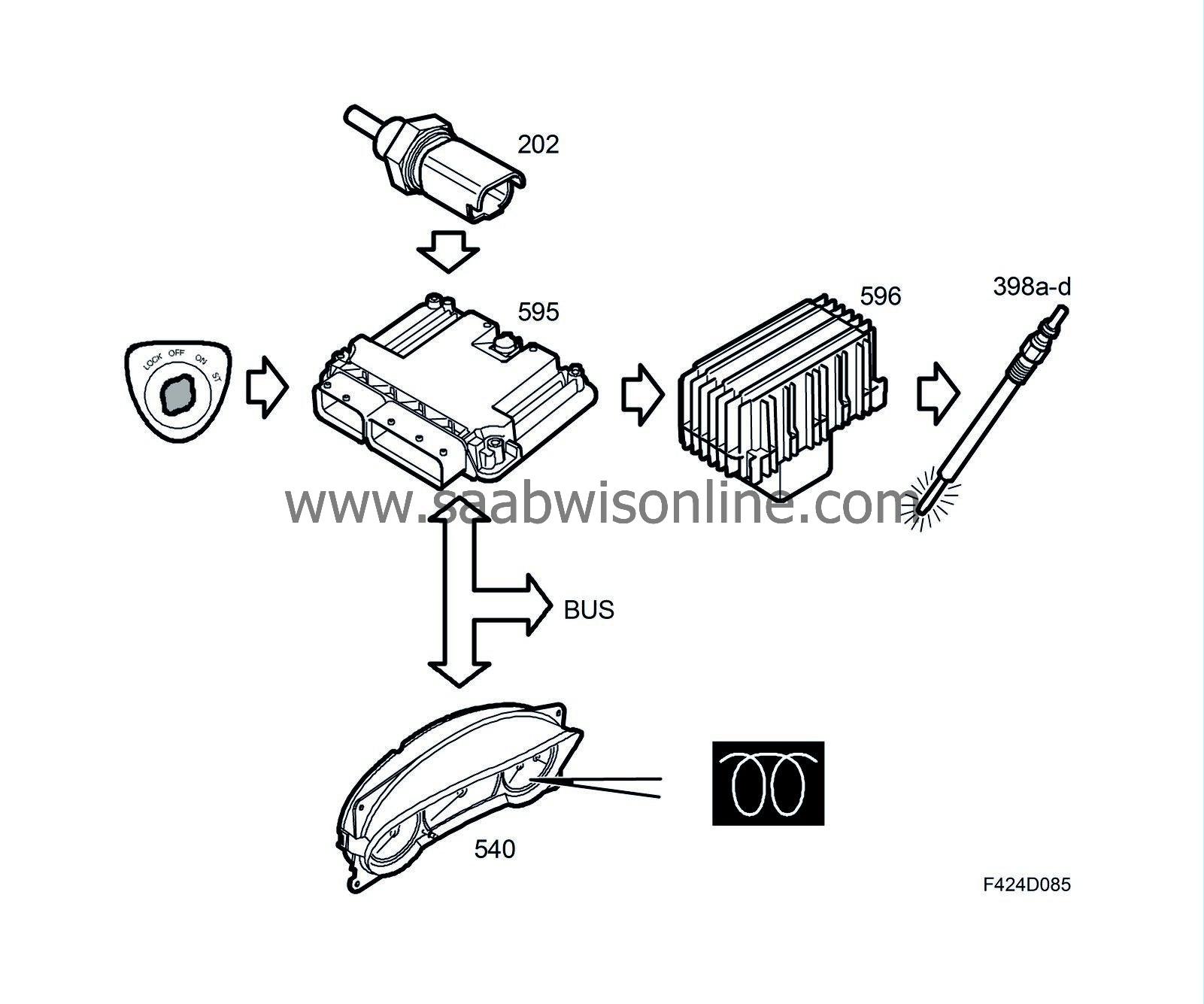
Starter heating
Starting glow is activated when the engine is started and the coolant temperature low. It is switched off once the engine is considered to have started and is replaced by afterglow.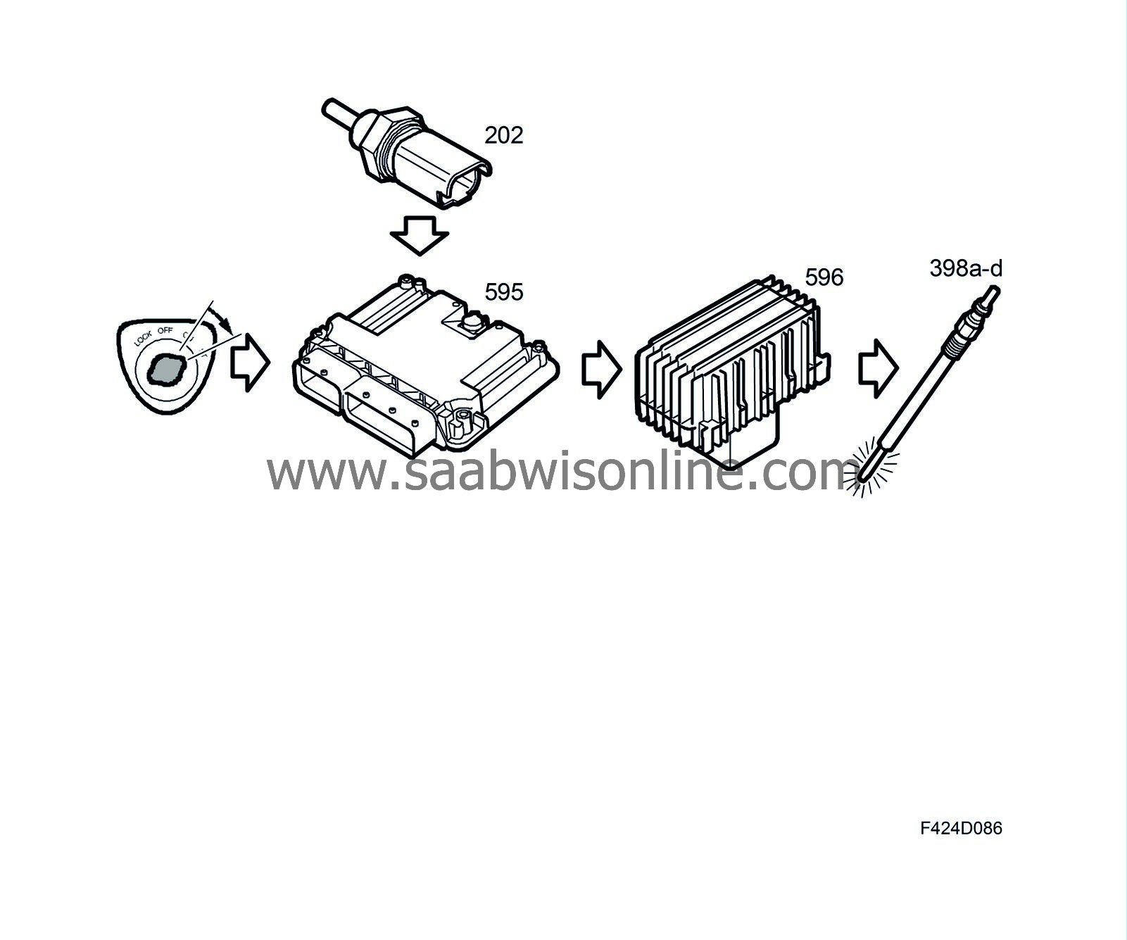
After-heating
Afterglow follows start glow, once the engine is considered to have started. Its purpose is to reduce misfiring and give smoother running by making sure the combustion chamber heats up while combustion does not produce sufficient heat to ensure ignition. Afterglow is switched off after a certain time, which depends on the coolant temperature. It is also switched off if the engine speed or quantity of injected fuel exceed its limits. If the engine speed or fuel quantity should drop under the limit values, afterglow is re-engaged provided the coolant temperature dependent period has not ended.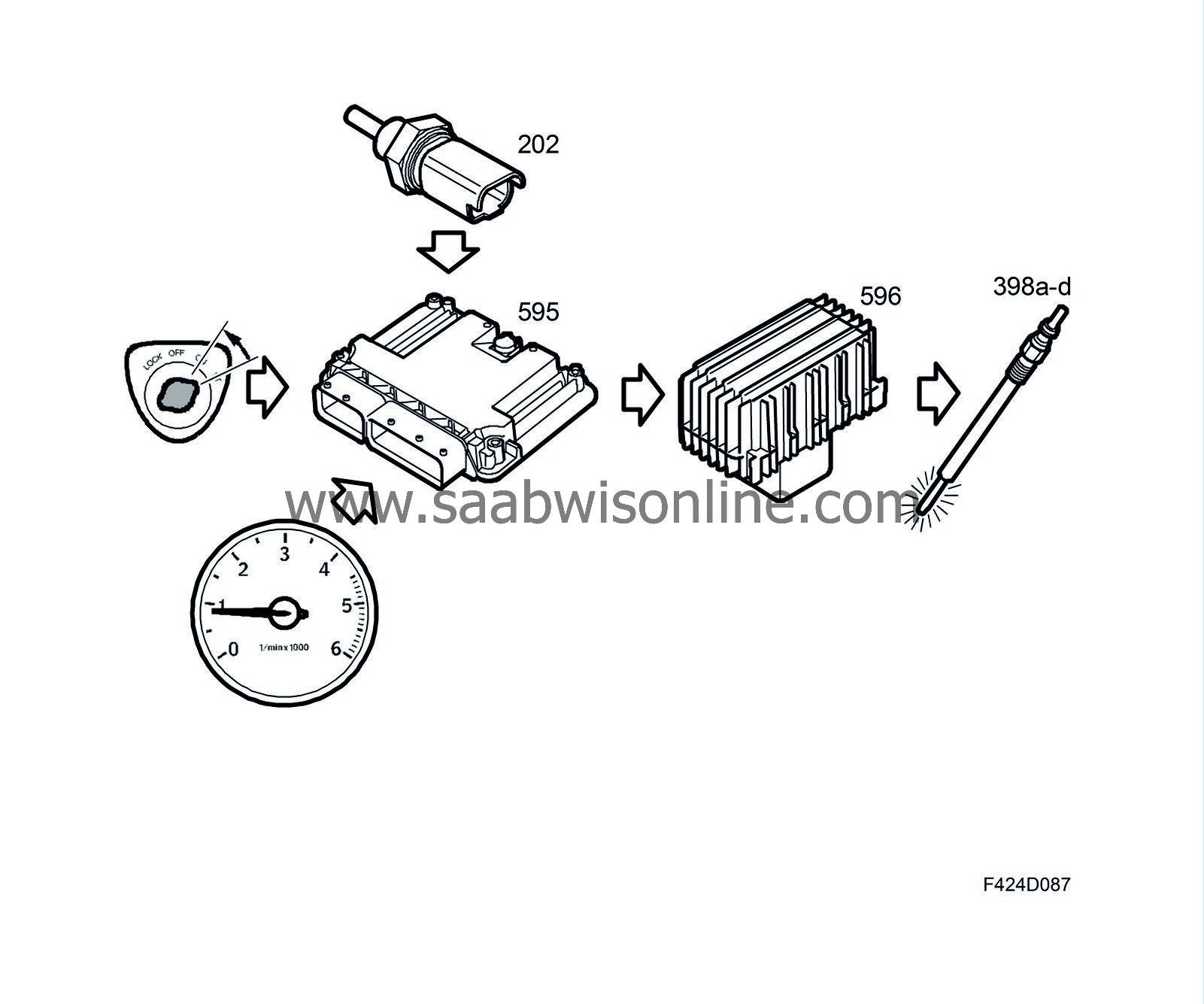
Intermediate heating
To limit combustion chamber cooling at low fuel quantities or during engine braking (fuel quantity = 0), the intermediate glow function may be activated. This reduces blue smoke produced during subsequent acceleration.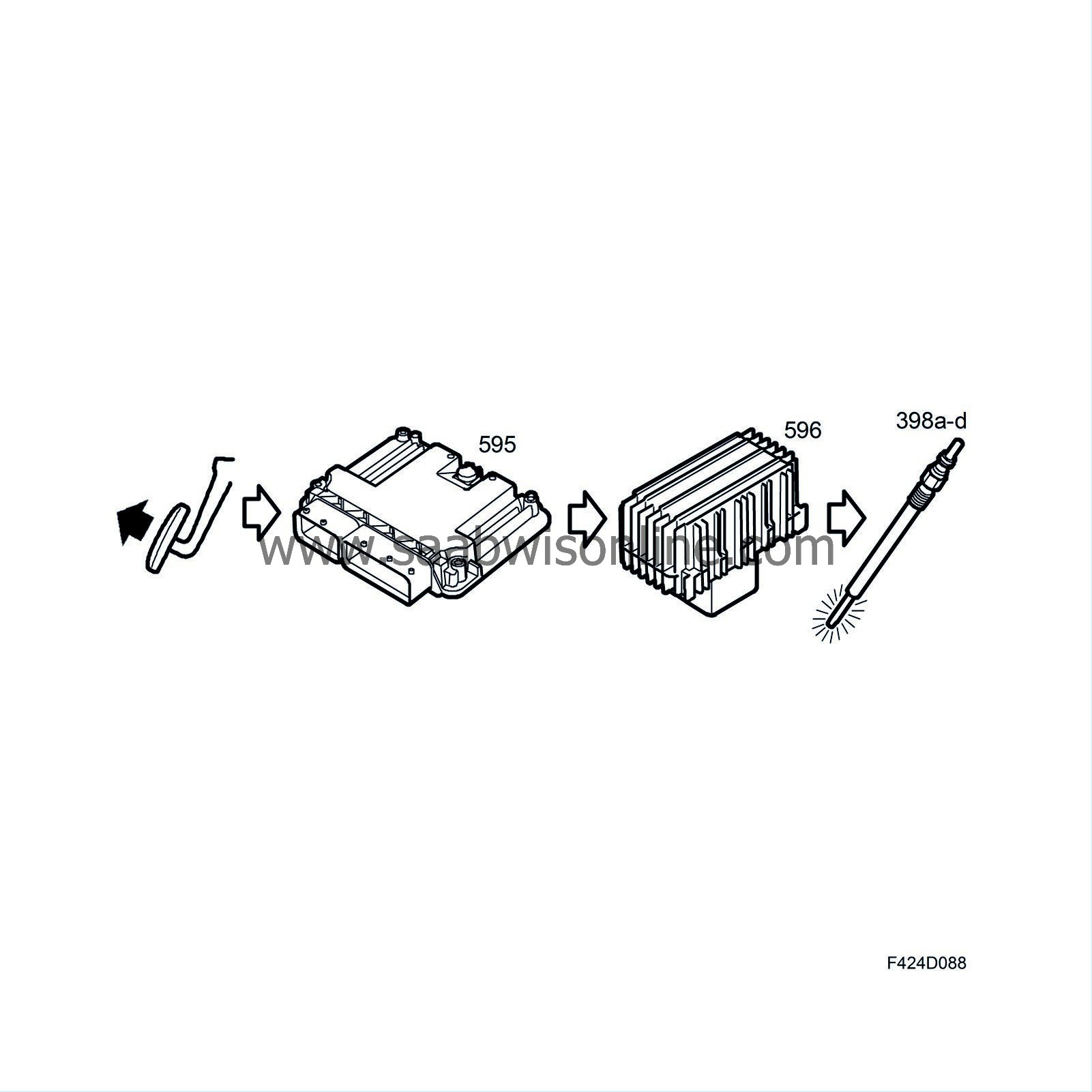
The intermediate glow function may also be activated during particle trap regeneration if the engine load is relatively low. The glow plugs' large power consumption increases the load on the generator, which in turn requires more engine torque. The ECM will compensate for the increased torque by increasing the fuel quantity that is injected. The result is hotter exhaust gases and increased exhaust gas flow through the particle filter.
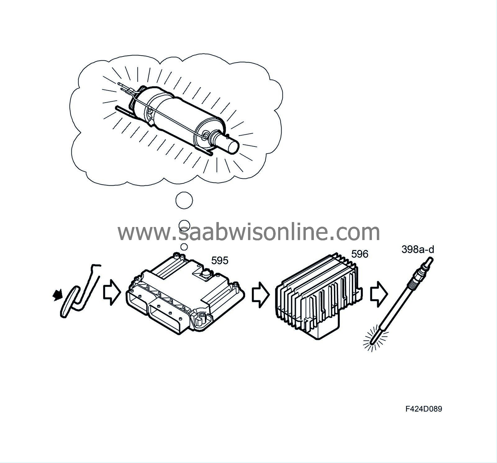
Intermediate glow is not activated for regeneration at high engine loads.
