Closed loop
| Closed loop |
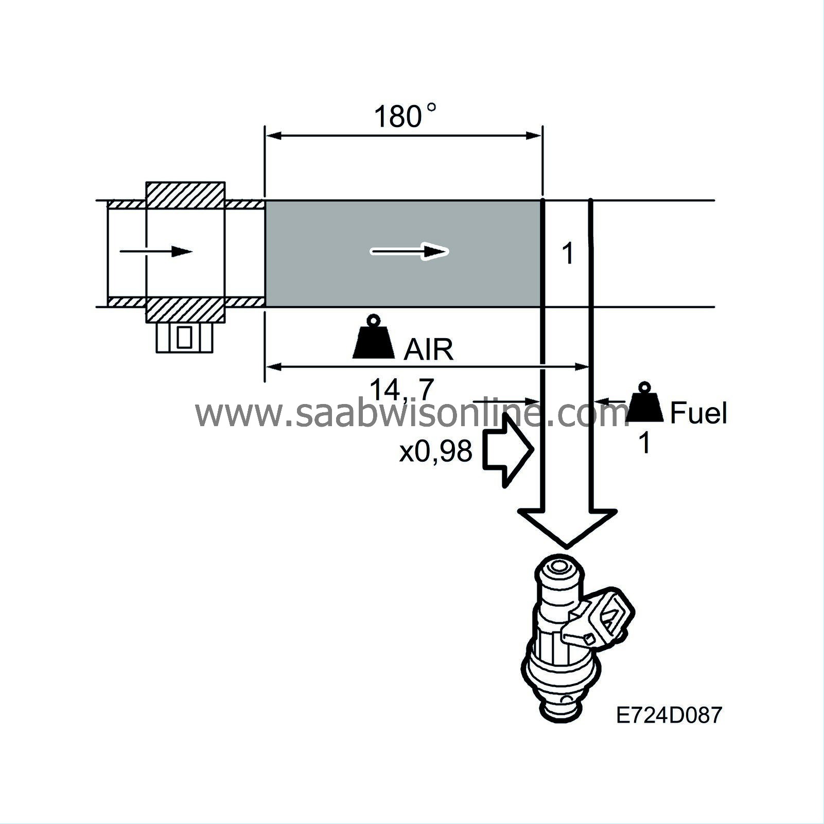
The basic fuel quantity has been calculated to give the air/fuel ratio 14.7:1. The calculation is based on the value from the mass air flow sensor. Air leaks and tolerances in the mass air flow sensor can affect the calculation. When the fuel quantity is subsequently converted to injection duration, the control module assumes that the flow through the injectors is faultless. Tolerances in the injectors and variations in the fuel pressure can affect the calculation.
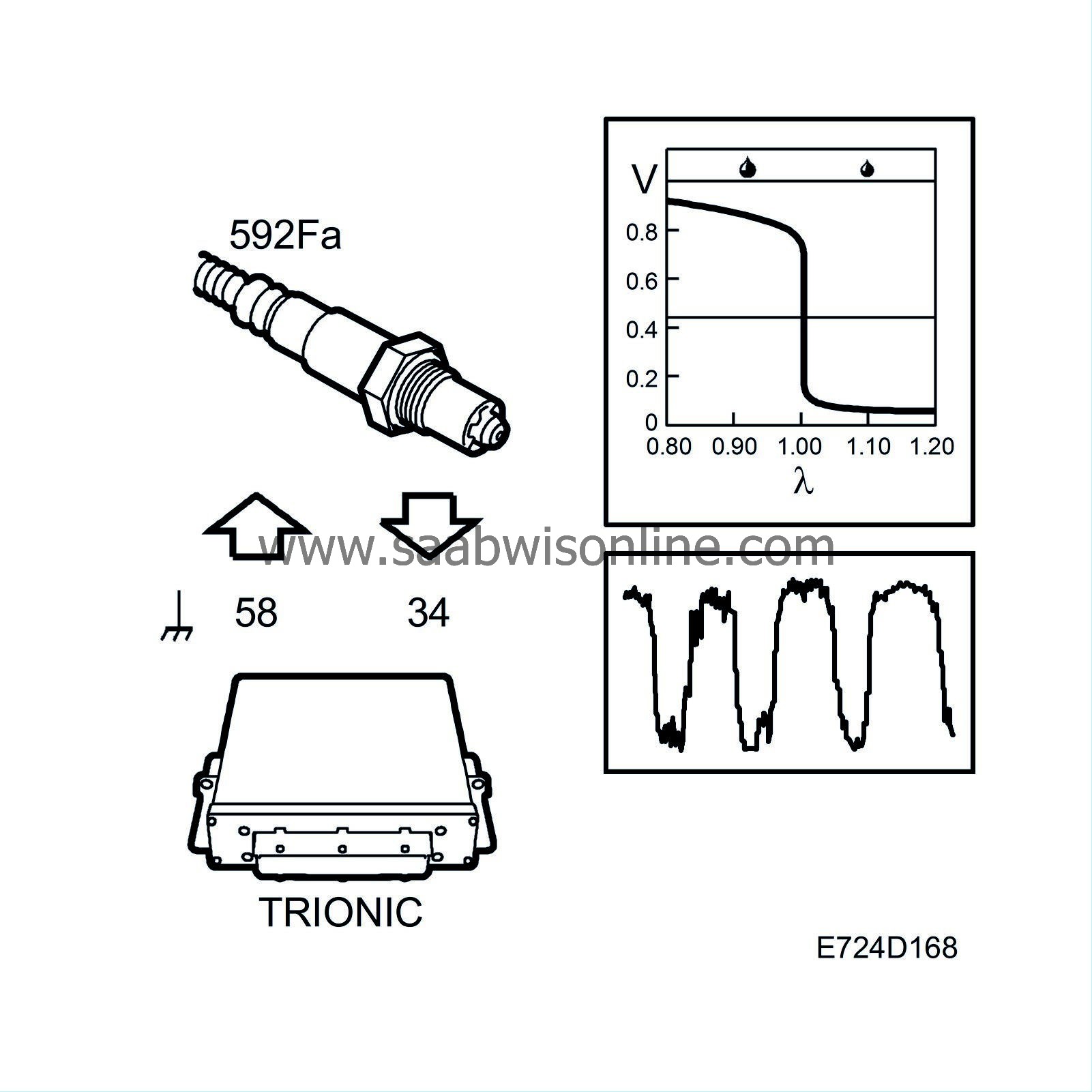
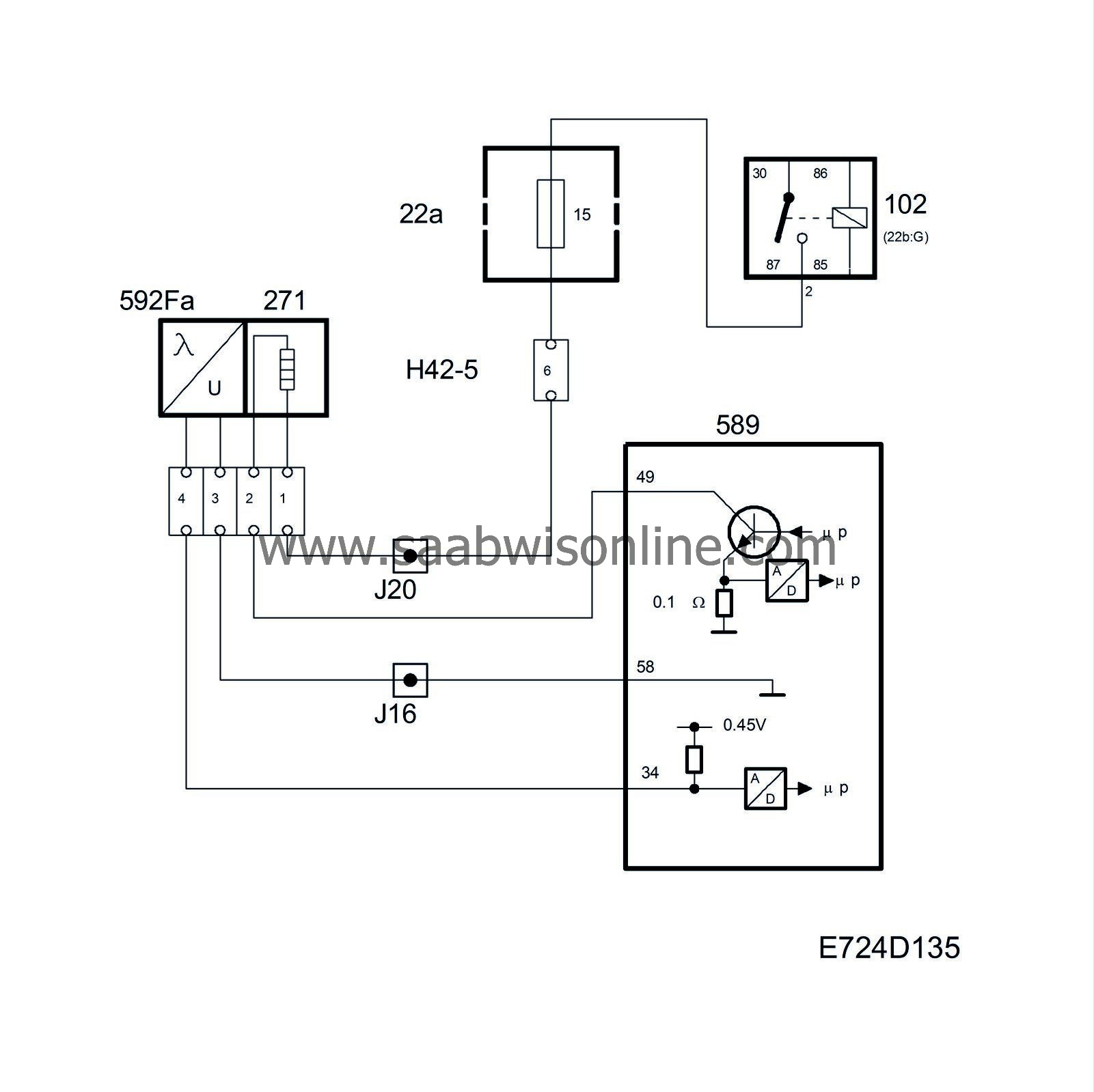
To work well, the catalytic converter requires an air/fuel ratio of precisely 14.7:1. Therefore the system is fitted with an oxygen sensor, called oxygen sensor 1 or O2S 1, mounted before the catalytic converter. The oxygen sensor is connected to control module pin 34 and grounded via control module pin 58.
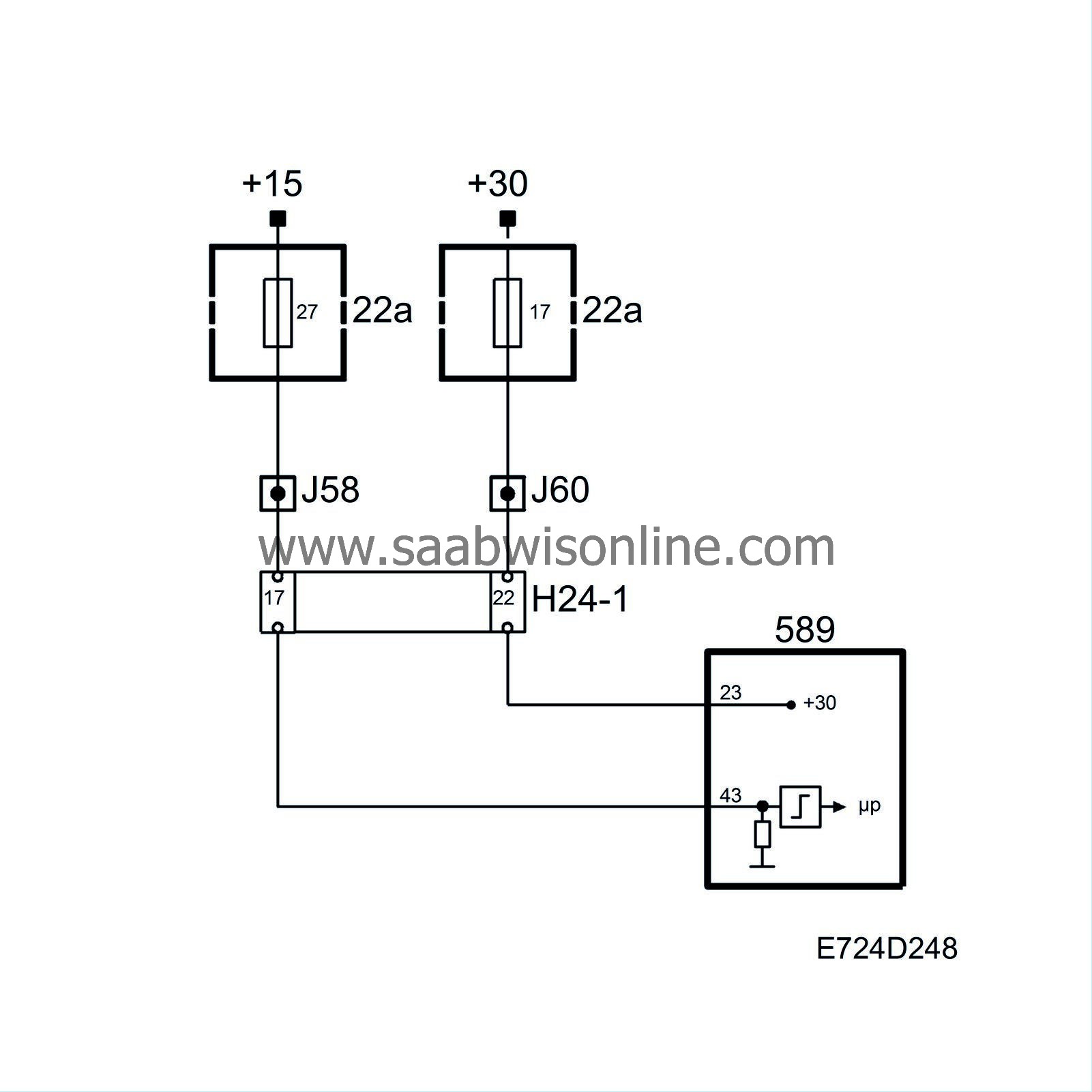
To be able to quickly supply voltage after starting, the oxygen sensor must be preheated. Preheating is fed with B+ from the fuel pump relay via fuse 15 and is grounded via control module pin 49. To be able to regulate the preheating, the grounding of the preheating circuit is pulse width modulated.
The control module estimates the exhaust gas temperature based on the load and engine speed. When the exhaust gas temperature is high, the pre-heating is de-activated to avoid damaging the oxygen sensor.
When the exhaust gases pass the oxygen sensor, their oxygen content is measured by a chemical reaction. The output voltage of the oxygen sensor is proportional to the current oxygen content, which is an indication of the composition of the air/fuel mixture. If the engine receives a richer mixture than normal (lambda below 1), the oxygen sensor output voltage will be approx. 0.9V. If the engine fuel mixture is leaner than normal (lambda above 1), the oxygen sensor output voltage will be approx. 0.1V.
The sensor voltage changes rapidly as lambda passes 1.
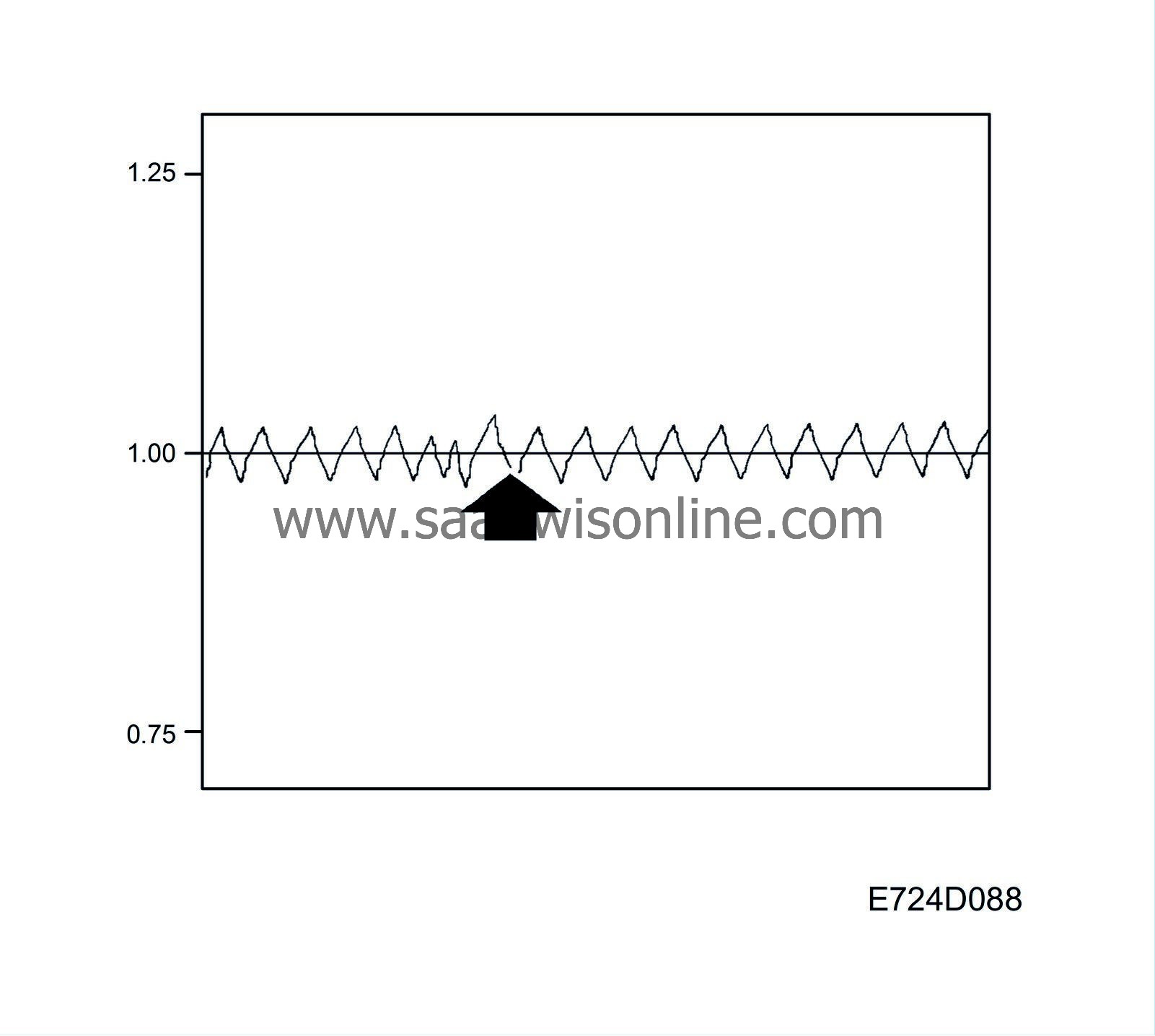
The closed loop factor is 1.00 when closed loop is not active. As soon as closed loop is activated, the oxygen sensor voltage is allowed to affect the factor for closed loop. If the oxygen sensor delivers a voltage below 0.50V, the correction factor will slowly be increased. On the other hand, the correction factor will slowly be decreased if the oxygen sensor voltage output exceeds 0.50V.
The end limits for the correction factor are 0.75 and 1.25 respectively.
The diagnostic tool always indicates 0% when closed loop is not active, 25% when the correction factor is 1.25 and -25% when the correction factor is 0.75.
The following conditions must be fulfilled before closed loop can be activated:
| • |
The engine speed exceeds 500 rpm
|
|
| • |
Engine must have run for 100-300 revolutions since starting. The value depends on the engine coolant temperature.
|
|
| • |
Oxygen sensor voltage must have passed below 0.4V or above 0.6V at some time since starting.
|
|
| • |
At idling speed, the engine coolant temperature must exceed approx. 15-30°C, depending on the starting temperature.
|
|
| • |
Under conditions of partial load, the engine coolant temperature must exceed approx. 10-30°C, depending on the starting temperature.
|
|
| • |
There must be no simultaneous fuel compensation for knocking or high load.
|
|
| • |
Engine load above 50 mg/c.
|
|
| • |
No fuel compensation for load changes when the engine coolant temperature is below 40°C.
|
|
| Diagnostics, oxygen sensor 1. |
| • |
If the sensor lead is short-circuited to the preheating circuit ground, diagnostic trouble code P1133 will be generated.
|
|
| • |
If the current in the oxygen sensor pre-heating circuit is too low, diagnostic trouble code P1135 will be generated.
|
|
| • |
If the current in the oxygen sensor pre-heating circuit is too high, diagnostic trouble code P1136 will be generated.
|
|
| • |
If the sensor lead is short circuited to ground, diagnostic trouble code P0131 will be generated.
|
|
| • |
If the sensor lead is short circuited to B+, diagnostic trouble code P0132 will be generated.
|
|
| • |
If the sensor reacts too slowly to changes in the fuel-air mixture or if its voltage transition is too far from lambda 1, diagnostic trouble code P0133 will be generated.
|
|
| • |
If there is an open circuit on any of the leads for the sensor ground or sensor voltage, the control module will continuously read 0.45V and diagnostic trouble code P0134 will be generated.
|
|
System reaction to a fault
| • |
Closed loop control system blocked.
|
|||||||
| Diagnostics, closed loop |
| • |
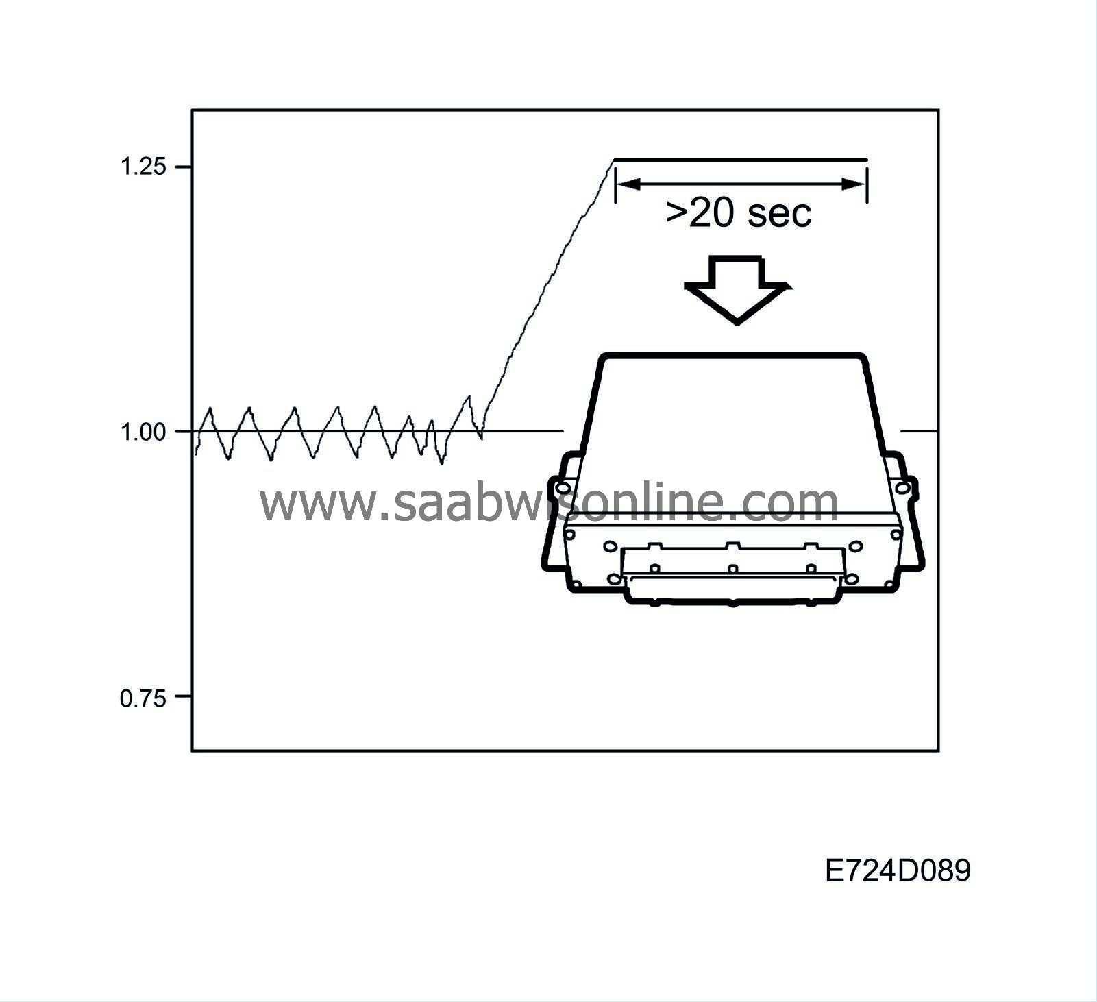
At a correction factor of 0.75, the system will read a rich air/fuel mixture and the fuel quantity has been reduced as much as possible. If this state persists for longer than 20 seconds, diagnostic trouble code P1172 will be generated. The fault can be caused by the following:
|
|
| - |
Air leak between the compressor and the throttle.
|
| - |
Purge valve stuck open.
|
| - |
Defective mass air flow sensor.
|
| - |
Fuel pressure too high.
|
| • |
Correspondingly, at a correction factor of 1.25, the system will read a lean air/fuel mixture and the fuel quantity has been increased as much as possible. If this state persists for longer than 20 seconds, diagnostic trouble code P1171 will be generated. The fault can be caused by the following:
|
|
| - |
Air leak after the throttle.
|
| - |
Low fuel pressure.
|
| - |
Defective mass air flow sensor.
|
| - |
Blocked injectors.
|
| • |
If closed loop fails to be activated within a reasonable time after start, diagnostic trouble code P0125 will be generated.
|
|
| Oxygen sensor 2 |
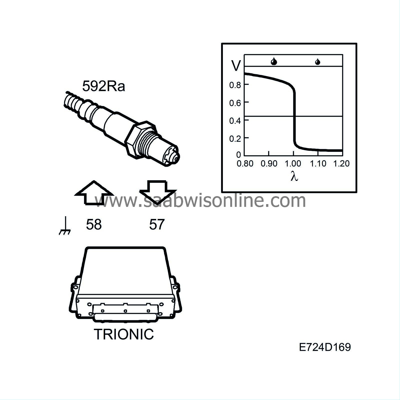
To be able to diagnose the front catalytic converter an oxygen sensor has been fitted after it on the exhaust system. The sensor is called oxygen sensor 2 or O2S 2. The oxygen sensor is connected to pin 57 on the control module and grounded from pin 58.
To be able to quickly supply a voltage after starting, the oxygen sensor must be preheated. Preheating is fed with B+ from the fuel pump relay via fuse 15 and is grounded via control module pin 2. To be able to regulate the preheating, the grounding of the preheating circuit is pulse width modulated.
Preheating is activated as soon as the engine coolant temperature exceeds 30°C.
The control module estimates the exhaust gas temperature based on the load and engine speed. When the exhaust gas temperature is high, the pre-heating is de-activated to avoid damaging the oxygen sensor.
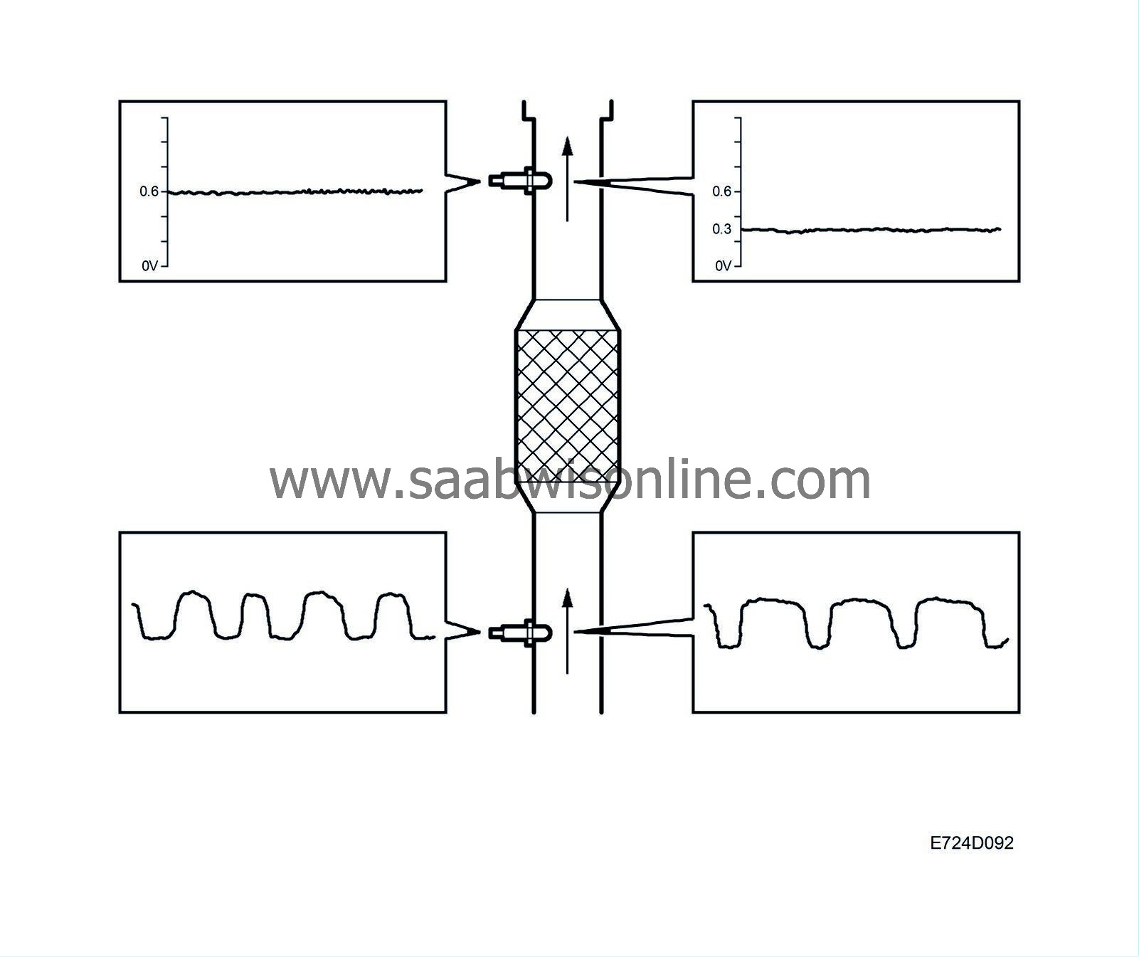
If the catalytic converter is damaged, its ability to absorb oxygen will deteriorate. The normal fluctuations of the closed loop will then be detected on the voltage from oxygen sensor 2 and a diagnostic trouble code will be generated. The diagnosis is performed once per driving cycle.
In addition to the catalytic converter diagnosis, the oxygen sensor value is also used to correct the closed loop for minor faults in oxygen sensor 1.
Optimum emission values are obtained when the voltage from oxygen sensor 2 is 0.6V.
If the voltage is 0.3V, for example, the engine is running slightly lean. the closed loop correction factor will then be blocked in the rich setting for a certain number of combustions before oxygen sensor 1 is allowed to affect the value again.
| Diagnosis |
Oxygen sensor 2
| • |
If the current in the oxygen sensor pre-heating circuit is too low, diagnostic trouble code P1141 will be generated.
|
|
| • |
If the current in the oxygen sensor pre-heating circuit is too high, diagnostic trouble code P1142 will be generated.
|
|
| • |
If the sensor lead is short circuited to B+, diagnostic trouble code P0138 will be generated.
|
|
| • |
If there is an open circuit on any of the leads for the sensor ground or sensor voltage, or if the sensor voltage is short circuited to ground, diagnostic trouble code P0140 will be generated.
|
|
| • |
If the sensor lead is short-circuited to the preheating circuit ground, diagnostic trouble code P1137 will be generated.
|
|
System reaction to a fault
| • |
Transition adaptation of closed loop is blocked.
|
|||||||
Three way catalytic converter
| • |
If the catalytic converter is damaged, diagnostic trouble code P0420 will be generated.
|
|

