(854-2579) ACC has difficulty controlling and maintaining the temperature on the driver's side
Symptom: ACC has difficulty controlling and maintaining the temperature on the driver's side.
| TECHNICAL SERVICE BULLETIN | |
| Bulletin Nbr: | 854-2579 |
| Date: ........... | April 2006 |
| Market: | all |
| ACC has difficulty controlling and maintaining the temperature on the driver's side |
| Cars affected |
Saab 9-5 M04-
LHD: from and including Vehicle Identification Number 43010217
RHD: from and including Vehicle Identification Number 43013833
| Background |
The air mixing damper (heater damper) shaft may crack at which temperature control operates unsatisfactorily. This may also be intermittent.
The diagnostic trouble codes B2295 and B2495 may be generated (up to and including Vehicle Identification Number 43014440).
In many cases the air mixing damper shaft is only cracked in the outer end to the stepping motor, and can then be repaired using this method. Consequently, repairs in accordance with TSB 854-2411 ed. 2 (US/CA) or 854-2396 ed. 2 (other markets) respectively are not necessary.
In the case of customer complaint the air mixing damper shaft must be checked in accordance with the following method.
Symptom description
ACC has difficulty controlling and maintaining the temperature on the driver's side.| Parts required |
12 765 864 Shaft, heater damper motor
| Procedure |
| 1. |
Clear any diagnostic trouble codes using Tech2.
|
|
| 2. |
Start the engine.
|
|
| 3. |
Select panel setting on the ACC panel. Check that the panel vents are in the open position.
|
|
| 4. |
Wait until the system has stabilised (approx. 30 seconds) and then set the temperature to LO on both the driver's and passenger side.
|
|
| 5. |
Use your hand to check that air is flowing from the panel vents.
|
|
| 6. |
Select defroster setting.
|
|
| 7. |
Wait until the system has stabilised (approx. 30 seconds) and then use your hand to check that air is flowing from the vents above the dashboard.
|
|
| 8. |
Repeat the check in accordance with steps 3 to 7.
|
|
| 9. |
If the air flow is not changed but still blows from the same air vents then the fault is in the air distribution damper. For remedy see TSB 854-2461 (US/CA) or TSB 854-2450 (other markets) respectively.
|
|
| 10. |
Switch off the engine.
|
|
| 11. |
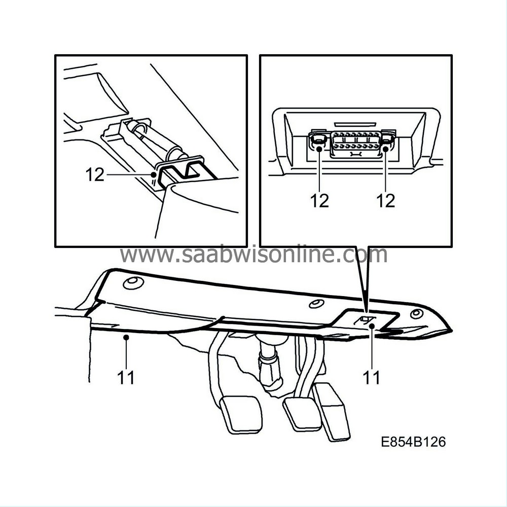
Remove the lower panel on the driver's side.

|
|
| 12. |
Detach the data link connector and lamp.
|
|
| 13. |
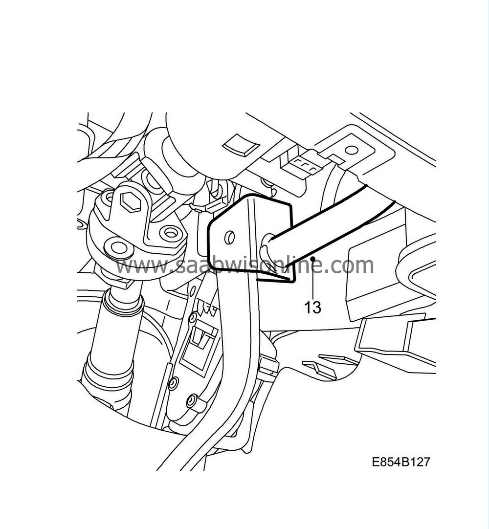
Remove the brake pedal strut.

|
|
| 14. |
Unplug the stepping motor connector for the air mixing damper.

|
|
| 15. |
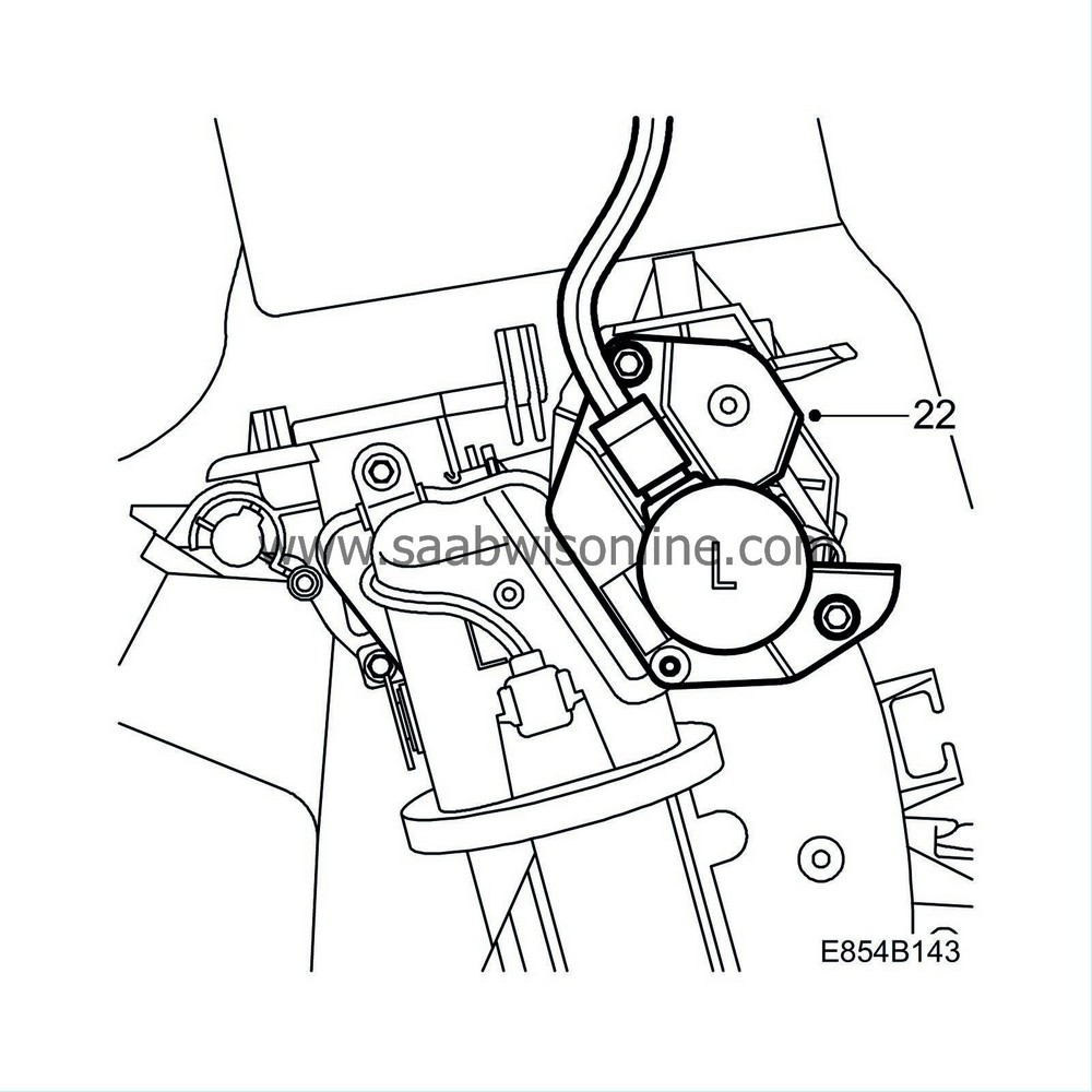
Remove the stepping motor.
|
|
| 17. |
If the shaft is not broken then check the function of the stepping motor (detached motor) using Tech2 (the "Activate" menu).
|
|
| • |
If the shaft and stepping motor are in working order then check whether the heat can be controlled manually by rotating the shaft manually (with the engine running).
|
| • |
If the heat cannot be controlled then the air mixing damper further inside the heating and ventilation unit may itself be broken. For further fault diagnosis see TSB 854-2411 ed. 2 (US/CA) or TSB 854-2396 ed. 2 (other markets) respectively.
|
| 18. |
Remove the air duct from the heating and ventilation unit. If the shaft is broken in accordance with A, B or C in the illustration then the spare part shaft cannot be used. For further repair see TSB 854-2411 ed. 2 (US/CA) or TSB 854-2396 ed. 2 (other markets) respectively.

|
|
| 19. |
If the shaft is cracked in accordance with step 16 then the spare part shaft can be used. Continue as follows.
|
|
| 20. |
Pull the short shaft out from the stepping motor using adjustable pliers.

|
|
| 21. |
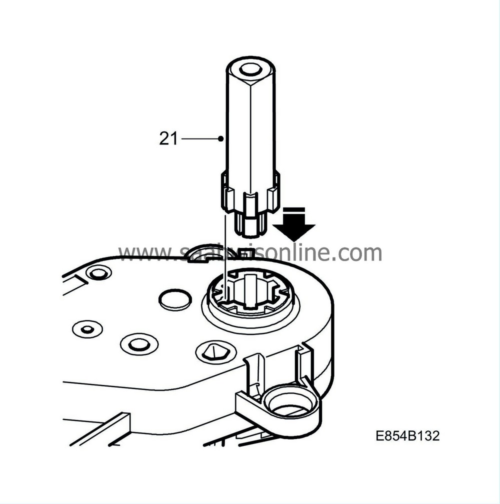
Rotate and press in the new long shaft.

|
|||||||
| 22. |
Fit the stepping motor for the air mixing damper.

|
|
| 23. |
Plug in the stepping motor connector.
|
|
| 24. |
Start the engine.
|
|
| 25. |
Wait to see whether the ACC system calibrates itself. Otherwise, calibrate the ACC system by simultaneously depressing the buttons.
|
|
| 26. |
Wait until system calibration is complete (approx. 30 seconds) and then set temperature 21 on both sides and select AUTO. Wait until the system has stabilised (approx. 30 seconds) and switch off the engine. Clear any diagnostic trouble codes.
|
|
| 27. |
Fit the brake pedal strut.

|
|
| 28. |
Attach the data link connector, lamp and lower panel.

|
|
| 29. |
Clear any diagnostic trouble codes.
|
|
| Warranty/Time Information |
In the case of customer complaint and if the car is within the warranty period , use the following information to fill out the claim:
Failed Object: 85434
Fault/Reason code: 71
Location code: 09 (US=3 drivers side)
Warranty Type (US): 01
Repair/Action code: 01
Labour Operation (US): 8543402
Labour Operation (CA): D0580
Time: 0.6 hr


