Detailed description
| Detailed description |
| Catalytic converters |
Two catalytic converters are used in combination to purify exhaust gases. These oxidise hydrocarbons (HC) and carbon monoxide (CO) into carbon dioxide (CO 2 ) and water (H 2 O). The catalytic converter system consists of a front catalytic converter and a catalytic converter integrated in the particle trap. Cars without particle trap and an additional catalytic converter.


Cars with particle trap:
The rear catalytic converter is integrated in the particle trap. It sits before the particle trap. Unlike the front catalytic converter, the rear catalytic converter has a ceramic monolith (carrier). The monolith is coated with platinum (Pt). Use of diesel fuel with high sulphur content can contaminate the catalytic converters.Cars without particle trap:
An additional catalytic converter is located downstream of the front catalytic converter. Unlike the front catalytic converter, the rear catalytic converter has a ceramic monolith (carrier). The monolith is coated with platinum (Pt). Use of diesel fuel with high sulphur content can contaminate the catalytic converters.
| Particle trap |
Cars with engine option Z19 can be equipped with a particle trap (market-dependent/option). This serves as a soot trap. The soot is combusted when the trap is full. This is called regeneration.

Structure
The particle trap consists of a porous ceramic body, similar to a catalytic converter, and has many small channels with porous walls.
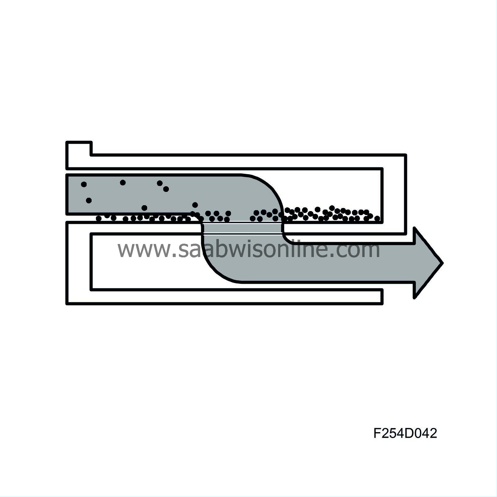
Every other channel is blocked in the rear (inlet duct) while the other channels are blocked at the front (exhaust duct).
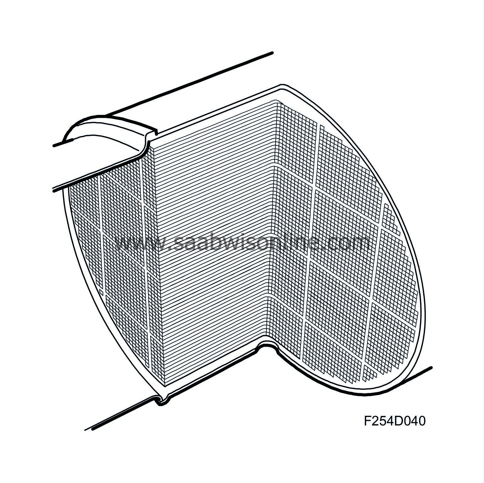
Exhaust gases are forced to flow into a channel that is blocked in the rear (inlet duct).

This duct is surrounded by exhaust ducts. The exhaust gases in the inlet duct pass through the porous walls. Since soot particles are too large to pass through the walls, the are caught in the particle trap.
Soot calculation
ECM calculates the amount of soot in the particle trap. Note that the differential pressure sensor (744) is not used to determine if the trap is full. It is used for diagnosis and to prevent manual regeneration via the diagnostic tool if the particle trap is insufficiently full. Calculation of soot quantity is primarily based on engine load and speed.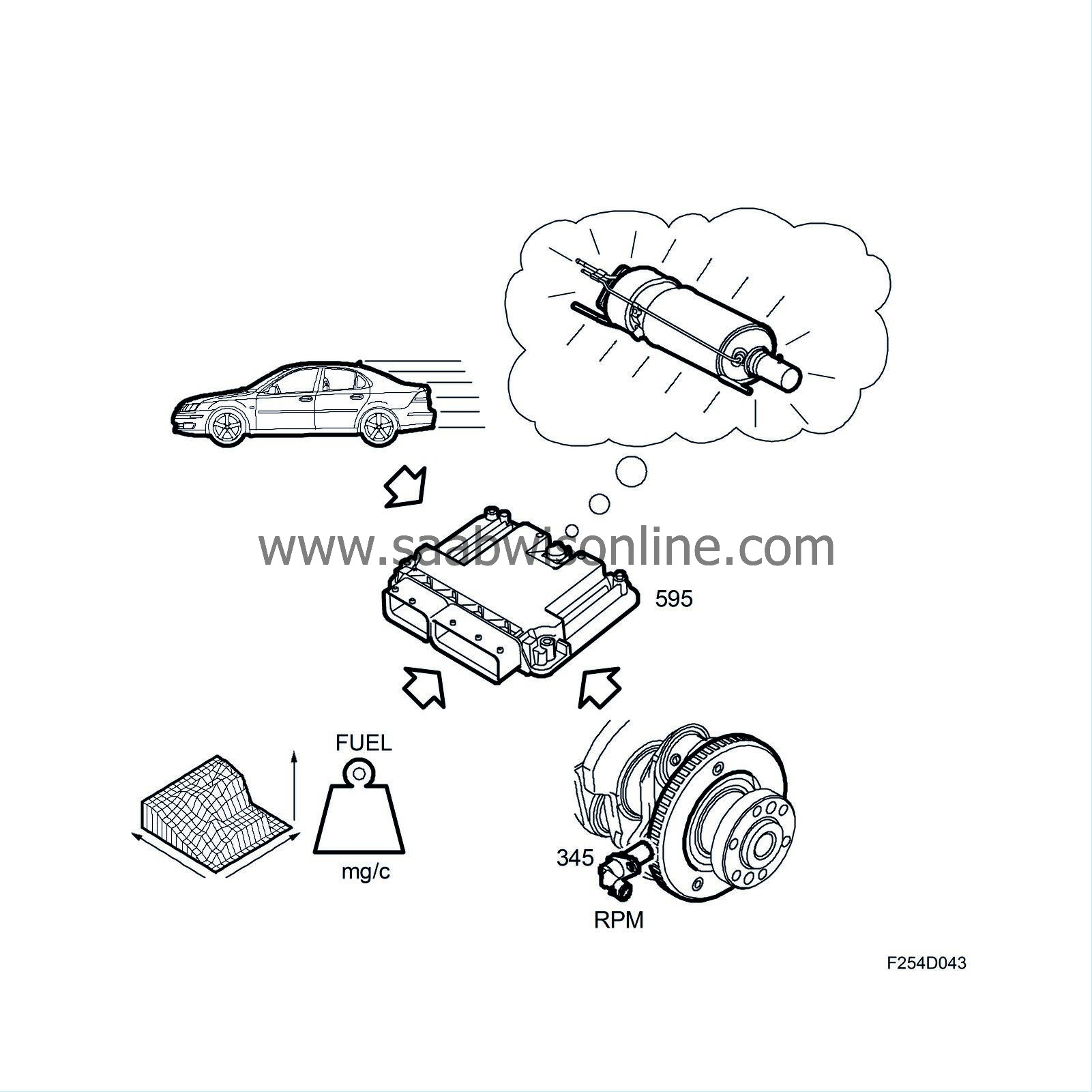
Automatic regeneration
ECM monitors driving style and determines when regeneration is necessary. A car that runs frequently at idling speed and low load will attempt regeneration sooner than a drive that drives often on motorways (i.e. at higher loads/engine speeds). Regeration requires temperatures over +550°C (1022 F) in the particle trap in order to combust the soot. The particle trap exhaust gas temperature sensor (602R) measures the temperature. If this temperature cannot be attained, ECM assumes regeneration is not possible and will attempt regeneration again at the next opportunity.To increase temperature in the particle trap in order to enable regeneration, there is an extra injection during the exhaust stroke. At about 160° after top dead centre, a small amount of fuel is injected in the cylinder. Since this fuel is injected so late (the piston is almost at bottom dead centre, exhaust valve open), the fuel does not add to torque. Exhaust gas temperature does not increase significantly either. The exhaust gases are simply enriched with HC (hydrocarbons), which starts a reaction in the front catalytic converter. The temperature of the gases increases, which is monitored by the front exhaust temperature sensor (602F). The heated exhaust gases continue into the particle trap where they first reach the rear catalytic converter. Here, temperature further increases to the minimum 550°C (1022 F) required for regeneration. If not, the soot is not combusted.

Regeneration continues until ECM calculates that all soot has been combusted. The exhaust gas temperature sensor valve, engine load and engine speed are the main parameters for this calculation. Regeneration can continue for up to 15 minutes. The driver will not notice any effect to engine running or performance.
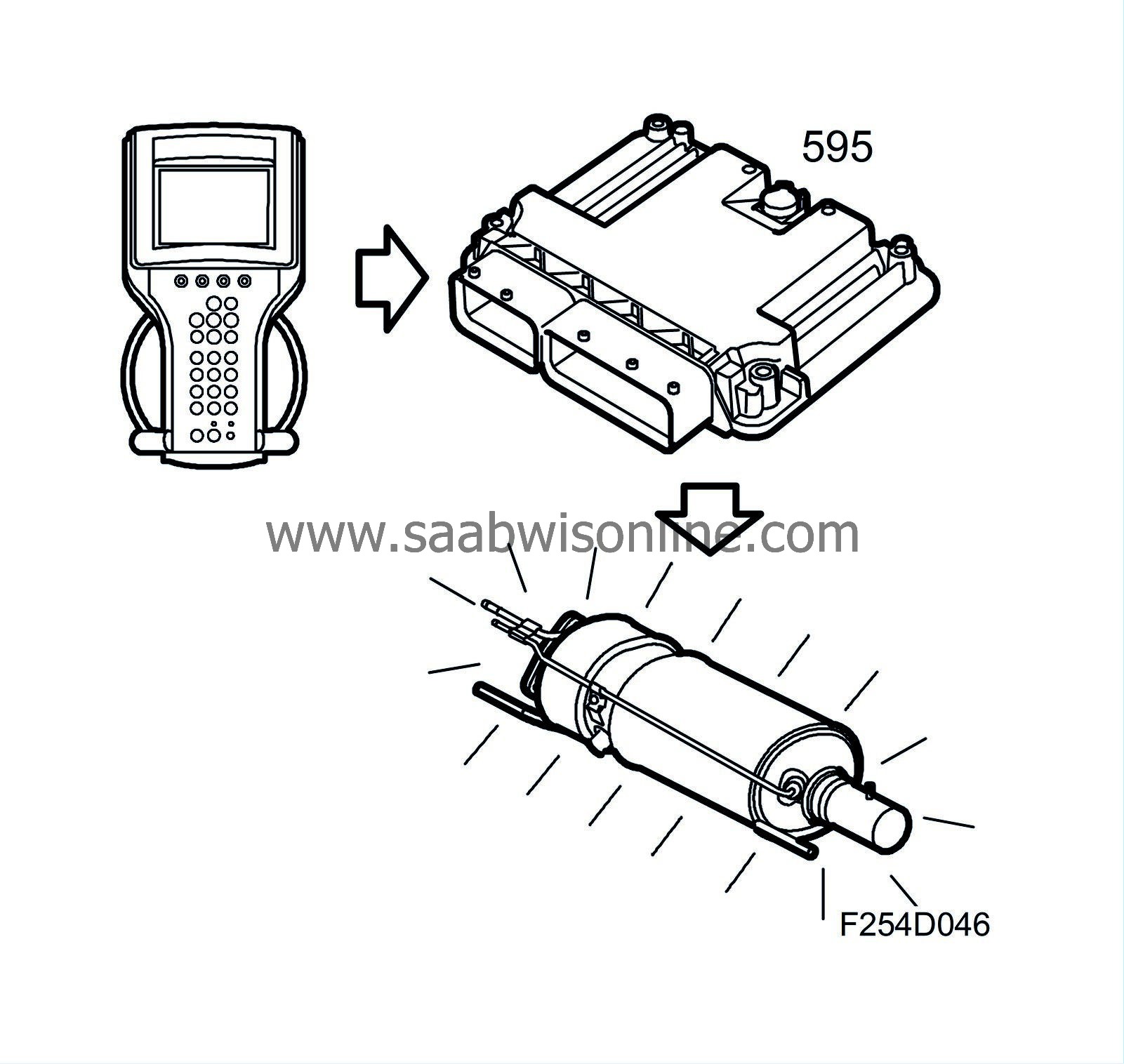
If the car is driven in such a way that regeneration is not possible, a diagnostic trouble code will be generated and the "Check Engine" lamp will illuminate. Regeneration must now be done manually using the diagnostic tool.

Manual regeneration
Automatic regeneration is not possible during certain driving conditions, such as extremely frequent light load driving with much idling. This will result in the generation of a diagnostic trouble code and illumination of the "Check Engine" lamp. Regeneration must now be done manually using the diagnostic tool.Upon ECM replacement, regeneration must be done manually using the diagnostic tool. See Manual regeneration LINK.
|
|||||||||||||
| Oxygen sensor (cars without particle trap) |
Cars without particle trap are equipped with an oxygen sensor mounted in the catalytic converter inlet. The oxygen sensor is a broadband sensor, meaning it can measure lambda value across a broad range unlike a conventional oxygen sensor that can only measure whether exhaust gases are on the rich or lean side of lambda 1. A narrow band sensor cannot be used for a diesel engine, which always works with a large surplus of air. The oxygen sensor measures the oxygen content of exhaust gases. Engine operating parameters are adjusted based on the lambda value so that exhaust gas emissions are as low as possible.

| Crankcase ventilation |
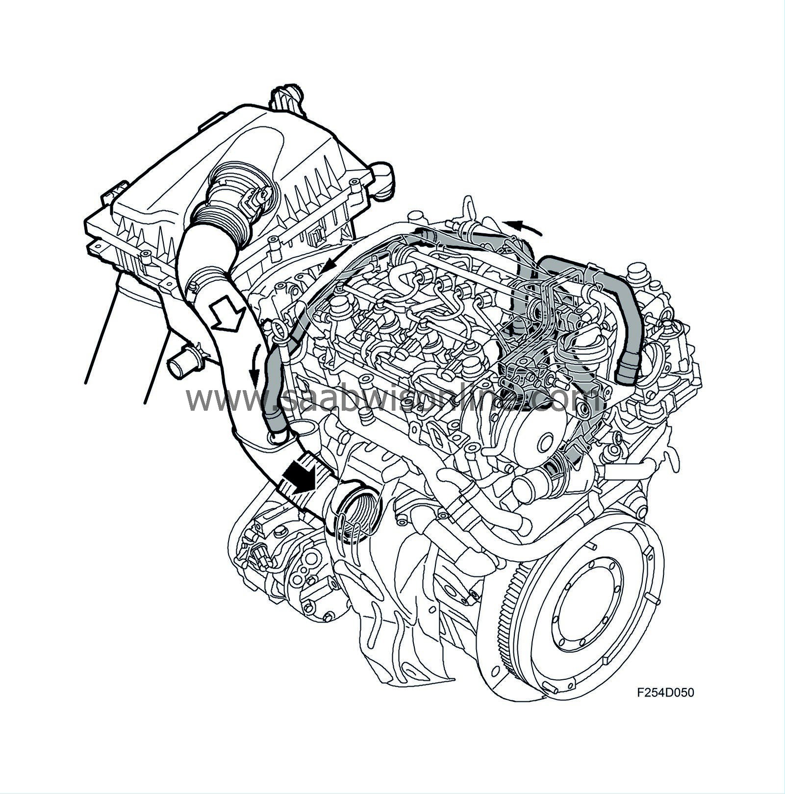
Engine crankcase ventilation is completely closed. The ventilation consists of a nipple at the oil filler and a nipple in the engine block which is connected with the crankcase and cylinder head. Hose branches run from each nipple and then unify into a single hose just before the oil trap. A hose runs from the oil trap and connects to the intake manifold between the mass air flow sensor and turbocharger. An oil return hose is fitted to the lower part of the oil trap and runs to the oil sump.

Crankcase gases that enter the oil trap are forced to rotate due to the shape of the cover in the oil trap. This causes heavier oil particles to fall out against the inside of the oil trap.
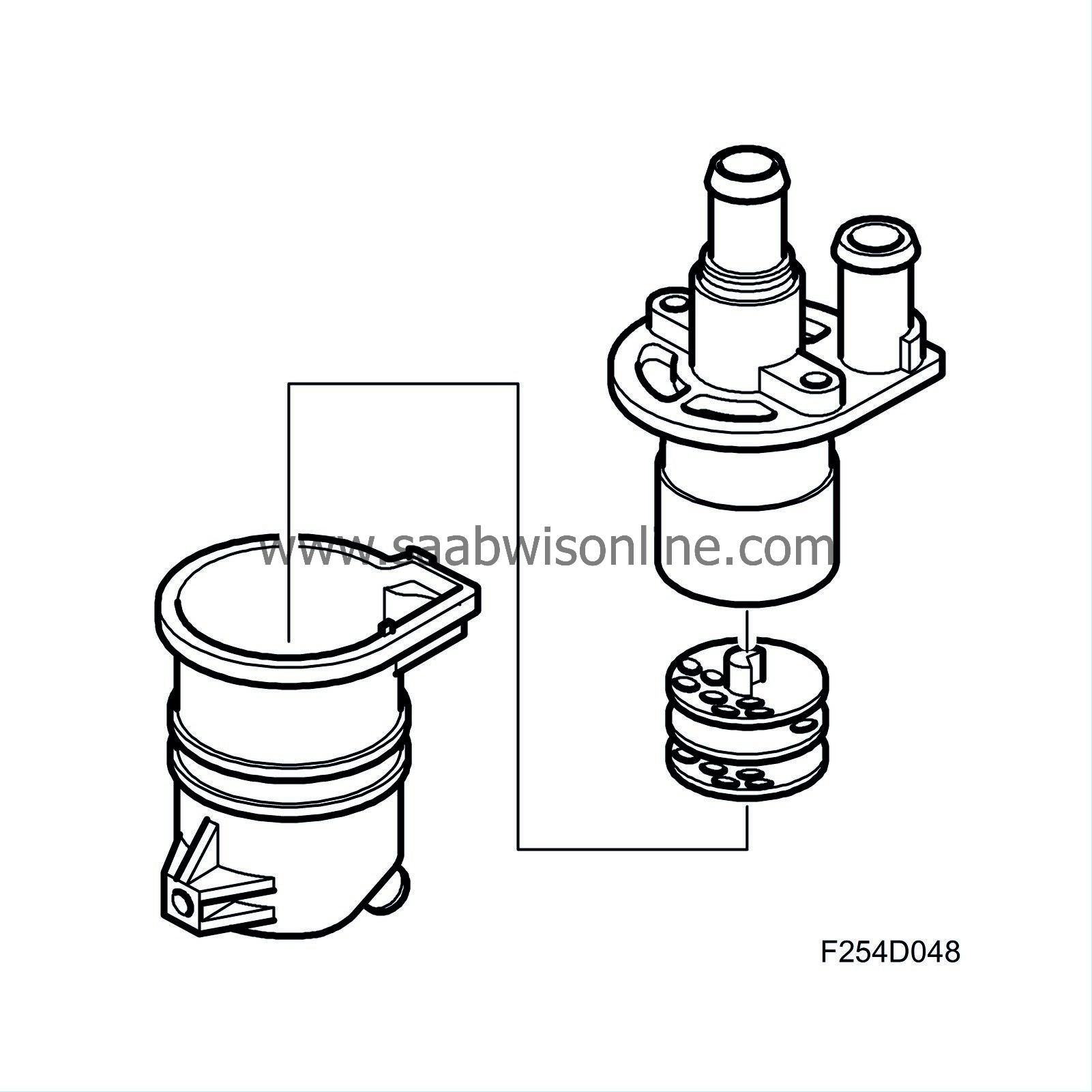
The centre of the oil trap houses three panels full of holes. The holes of the three panels are displaced so as to force the gas to switch direction several times. This further separates oil. A hood sits over the panels.
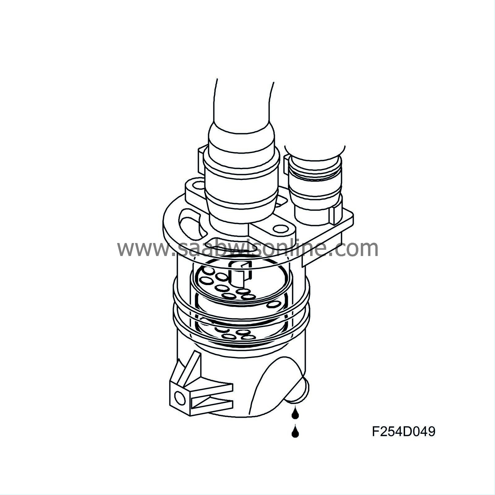
The direction of the gases is from down to up. After passing the last step of oil separation, crankcase gases go via a nipple in the oil trap to the turbocharger inlet, where the gases blend with intake air and are combusted in the engine.
| Exhaust Gas Recirculation (EGR) |
For a diesel engine, operating with excess air in combustion, there is currently no effective catalytic converter technology available for reducing NOx emissions. This means that the formation of nitrous oxides must be restricted.

With an EGR-system (Exhaust Gas Recirculation), a controlled amount of exhaust emissions are directed to the inlet side where they are mixed with the intake air. The result is slower combustion at a lower temperature and maximum pressure, which in turn hampers formation of NOx.

A pipe is connected to the exhaust manifold. This pipe leads exhaust gases to the EGR cooler, which allows the exhaust gases to pass through a number of tubes. The outside of the tubes are surrounded by engine coolant, which absorbs the heat from the exhaust gases. The cooled exhaust gases require less room, thus a greater exhaust mass can pass through the opening.

The cooled exhaust gases go via a pipe to the EGR valve (606), which is mounted on the engine intake manifold. The EGR valve is regulated by ECM, which calculates the amount of EGR required for each operation condition.
The EGR valve is electronically regulated by ECM. It also provides ECM information on its actual position.

Note there is no sensor measuring actual EGR flow. It is instead calculated as follows:
ECM contains a matrix describing how must air the engine cam pump at a specific operating condition. Let's say this calculation is 600 mg air per combustion (mg/c). ECM also calcualtes the amount of fresh air that must be available during this time, for example 450 mg/c. The difference is 150 mg/c. This difference is to be the EGR gases' share. ECM will open the EGR valve so that the value from the mass air flow sensor says that 450 mg/c air passes into the engine.


 Warning

