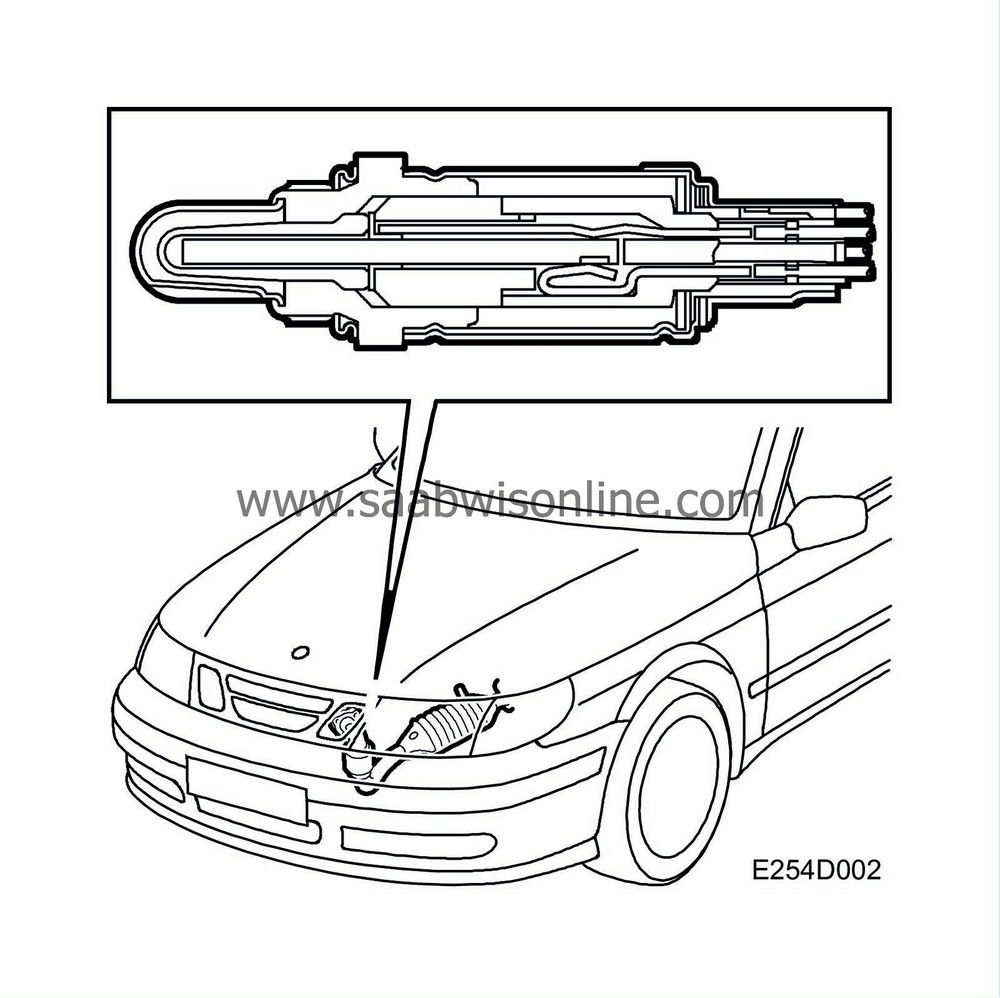
Closed loop fuel injection system
| Closed loop fuel injection system |
| Three way catalytic converter |
The car is equipped with a catalytic converter system comprising two catalytic converters connected in series. The aim of this is to reduce emissions, primarily with cold starting. The first catalytic converter (pre-catalytic converter) is located close to the turbocharger intake, where the exhaust gases are as hot as possible.
During cold starting it is important to reach operating temperature in the catalytic converter as quickly as possible. Locating it close to the turbocharger intake means that the exhaust gases cannot cool appreciably before they reach the catalytic converter.
In order to further increase purification capacity the car is equipped with a second catalytic converter (main catalytic converter).
The catalytic converters consist of a ceramic carrier that is coated with a porous layer which contains the catalytic materials rhodium and platinum. The cermet is housed in a double sheathed steel casing.
The catalytic converter has a high conversion rate on condition that the air-fuel mixture is stoichiometric, lambda 1. For petrol the ratio for lambda 1 that the air-fuel must maintain is 14.7:1.
If the air-fuel mixture is not maintained within this range then one or more gases will inevitably exceed the permitted values. A lambda controlled fuel injection system is a guarantee that the fuel-air mixture is completely correct. Normally slightly better emissions are obtained at lambda 0.99, accordingly slightly richer than lambda 1.
Provided that the closed loop fuel injection system gives an optimal fuel-air mixture ratio, the catalytic converter reduces the nitrous oxides (NO x ) and oxidises the carbon monoxide (CO) and hydrocarbons (HC). The end products are carbon dioxide (CO 2 ), water (H 2 O) and nitrogen (N 2 ).
In order for the catalytic converter to reduce the emissions, the car must be run on unleaded petrol only. This is because lead destroys the active components of the catalytic converter.
| Oxygen sensor |

The oxygen sensor consists of a primary cell with a solid electrolyte. The electrolyte is ceramic (zirconium dioxide) and temperature stabilised by the addition of a small quantity of yttrium oxide. The electrolyte is structured like a long and narrow disc.
To function properly, the catalytic converter requires an air-fuel ratio of precisely 14.7:1.
If the mixture is too lean, the oxygen content in the exhaust gases will increase. The oxygen sensor output voltage will then be about 0.1 V (lambda over 1). The engine control module reacts by extending the injection periods.
When the mixture is too rich, the oxygen sensor output voltage will be about 0.9 V (lambda under 1) and the injection pulses are shortened.
Since the working range of the oxygen sensor is between 200°C-850°C (392°F-1562°F), it is fitted with an electric preheater. Preheating is controlled by the system's control module. At high engine loads and speeds, the exhaust temperature is high and the preheating circuit is shut off.
For further information about closed loop control, see Group 2 “Engine management system”
 .
.


