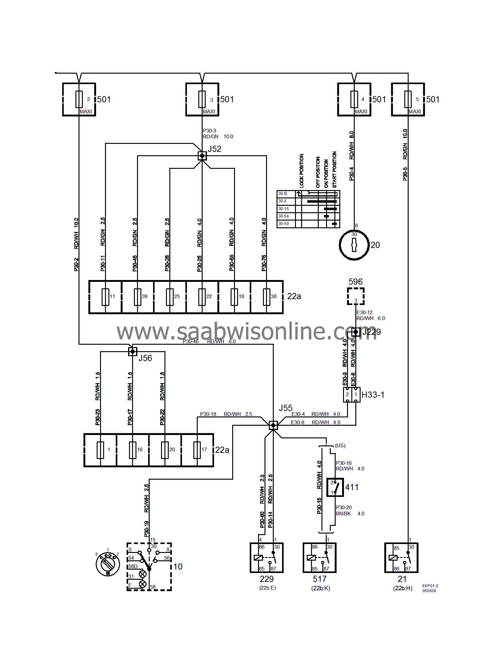
Power supply +30 (Part 2/2)
|
|
Power supply +30 (Part 2/2)
|

|
No.
|
Name
Location
|
Illustration
|
|
Components
|
|
10
|
Light switch,
on the instrument panel between the steering wheel and the driver's door
|

|
20
|
Ignition switch
in floor console between front seats
|

|
21
|
Relay, ignition switch,
in the relay box in the dashboard
|

|
22a
|
Fuse box, dashboard
on end of dashboard next to driver's door
|

|
229
|
Main relay, engine control system,
in the relay box in the dashboard
|

|
411
|
Switch, clutch, starter motor interlock
on bulkhead partition by clutch pedal
|

|
501
|
Main fuse box, maxi fuses,
under battery cover
|

|
517
|
Relay, starter relay
in the relay box in the dashboard
|

|
596
|
Glow plug control module,
by RH MacPherson strut tower
|

|
|
|
33-pin connector
|
|
H33-1
|
At the relay box in the dashboard
|

|
|
|
Crimp connectors
|
|
J52
|
Approx. 100 mm from branching of grounding point G30 towards maxi-fuse box
|

|
J55
|
LHD:
Approx. 125 mm from branching DICE control module towards the relay box
RHD:
Approx. 430 mm from grounding point G42 branching point towards DICE control module
|

|
J56
|
LHD:
Approx. 20 mm from the branching point of the DICE control module towards the engine bay lead-in
RHD:
Approx. 310 mm from rear edge of DICE control module connector towards engine bay
|

|
J229
|
Approx. 240 mm from connector H33-1
|

|