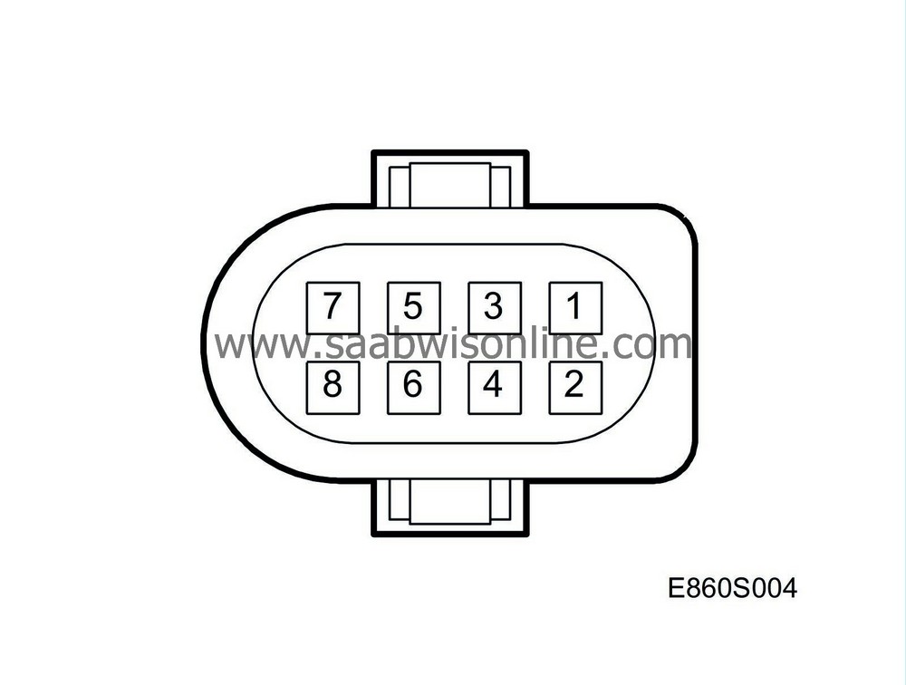
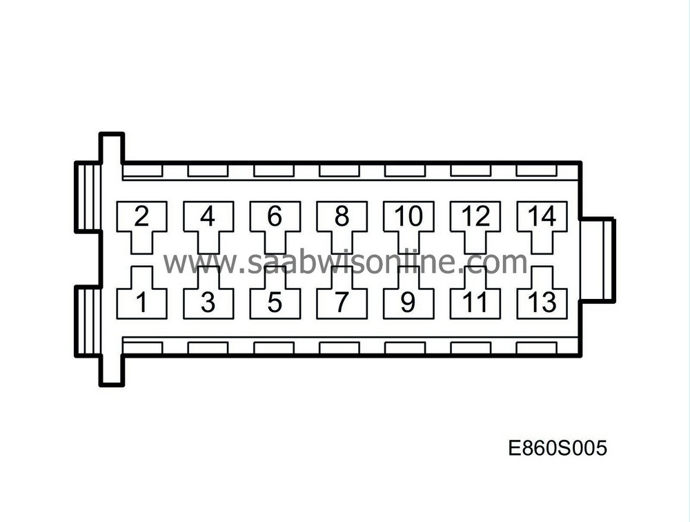
Test readings, control module connections
|
|
Test readings, control module connections
|
The following pages contain values and instructions for obtaining readings of signals and levels on the heater.
|
•
|
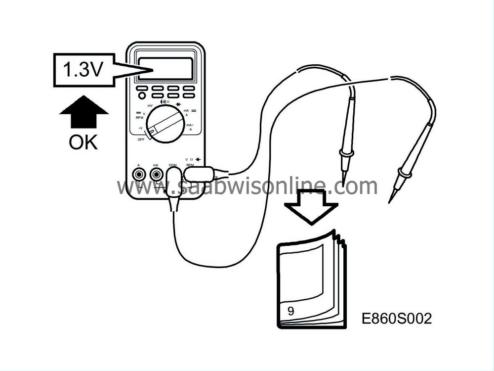
Note the test conditions and use your common sense when judging the test results.
|
|
•
|
Unless otherwise stated, the test readings presented are with the ignition switch in the ON position.
|
|
•
|
First check that the control module is supplied with current and grounded.
|
|
•
|
Then check all sensor inputs and signals from other systems.
|
|
•
|
Finally, check the control module outputs. Remember that the test readings do not indicate whether or not the actuator is in working order.
|
|
•
|
If any reading is not OK, consult the wiring diagram to trace the leads, connectors or components which ought to be checked more thoroughly.
|
|
•
|
The test readings given apply to a correctly calibrated Fluke 88/97.
|
|
•
|
The readings %(+) and ms(+) indicate the pulse ratio and pulse duration. A test instrument capable of measuring both pulse ratio and pulse duration must be used. The + sign denotes a positive trigger pulse (TRIG+).
|


> = greater than; < = less than;
»
= approximately equal to; ∼= alternating current
Pins with no additional comments have no pin connection. (LP = LOGIC PROBE; P = select pulse; p = perceptible pulses)
Pin
|
Component/Function
|
Input/Output
|
Test conditions
|
Across
|
Test reading
|
See
|
1
|
+30
|
|
|
1-B+
|
< 0.5 V
|

|
2
|
Ground
|
|
|
2-B-
|
< 0.1 V
|

|
3
|
MCC/ACC
|
|
|
|
|

|
4
|
Fuel pump
|
Output
|
|
4-2
|
»
10 Ohm
|

|
5
|
No connection
|
|
|
|
|

|
6
|
Main relay, heater
|
|
|
|
|

|
7
|
No connection
|
|
|
|
|

|
8
|
No connection
|
|
|
|
|

|

> = greater than; < = less than;
»
= approximately equal to; ∼= alternating current
Pins with no additional comments have no pin connection. (LP = LOGIC PROBE; P = select pulse; p = perceptible pulses)
Pin
|
Component/Function
|
Input/Output
|
Test conditions
|
Across
|
Test reading
|
See
|
1
|
Water pump +
|
Output
|
|
|
|

|
2
|
Water pump -
|
Output
|
|
|
|

|
3
|
Combustion air fan -
|
Output
|
|
|
|

|
4
|
Combustion air fan +
|
Output
|
|
|
|

|
5
|
Glow plug +
|
Output
|
|
5-6
|
0,8 - 0,9 Ohm
|

|
6
|
Glow plug -
|
Output
|
|
5-6
|
0,8 - 0,9 Ohm
|

|
7
|
No connection
|
|
|
|
|
|
8
|
No connection
|
|
|
|
|
|
9
|
Engine coolant temperature sensor 2
|
Input
|
|
9-10
|
As in diagram
|

|
10
|
Engine coolant temperature sensor 2
|
Input
|
|
9-10
|
As in diagram
|

|
11
|
Engine coolant temperature sensor 1
|
Input
|
|
11-12
|
As in diagram
|

|
12
|
Engine coolant temperature sensor 1
|
Input
|
|
11-12
|
As in diagram
|

|
13
|
Flame temperature sensor
|
Input
|
|
13-14
|
As in diagram
|

|
14
|
Flame temperature sensor
|
Input
|
|
13-14
|
As in diagram
|

|


